


It’s not everyday I take apart a (reasonably pricey) microphone! But, I was curious, and taking things apart is sometimes how one learns.
A long time ago I took apart an Echo Dot, which contains very different microphone technology (MEMS devices, seven-fold), so check that out too if it's of interest.
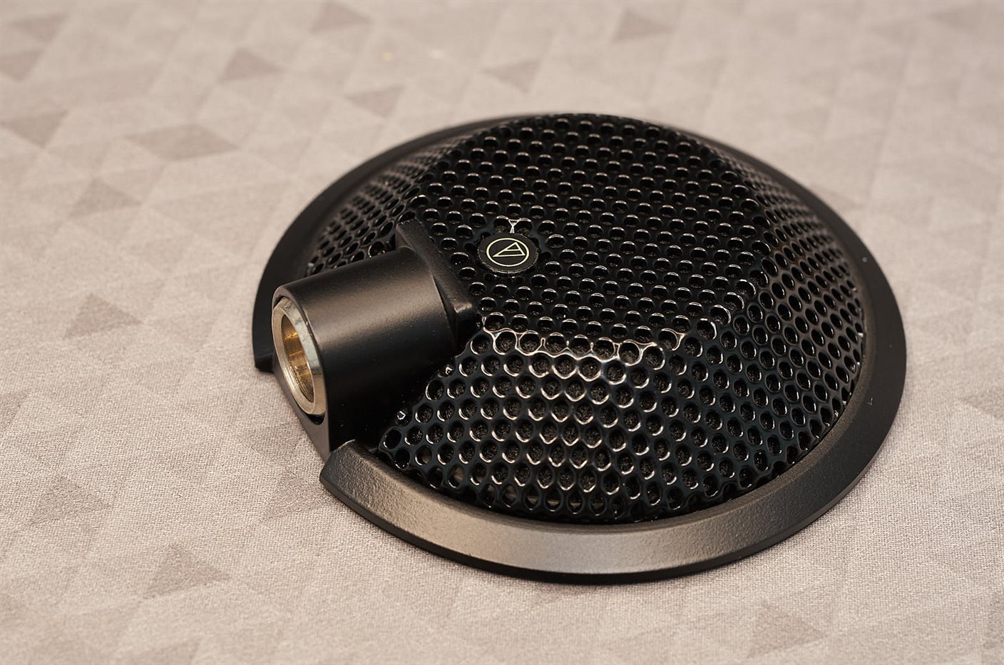
Anyway, the U841A is an electret condenser mic, intended for (I believe) speech for audio/videoconferencing purposes. Hopefully any audio experts can provide more detail.
The microphone is very ruggedly built. The secret to opening it up, is to peel off that tiny circular logo on the top; it reveals a screw : ) Then the stamped metal grille lifts off.
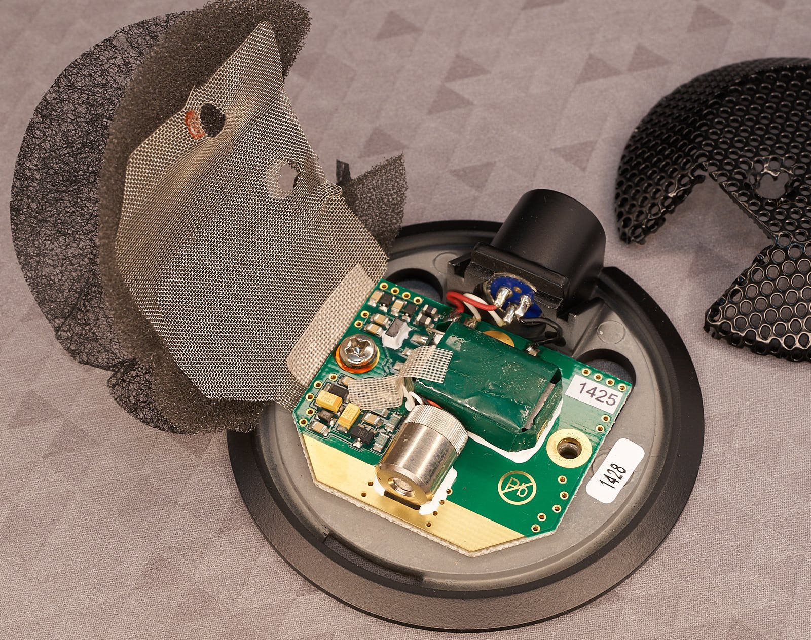
There’s a lot to visually unpack just from the photo below. On the left, you’ll see three material layers; a thin (0.2 mm) stiff layer (kind of like collar lining! there must be a technical name for it..), followed by 2 mm thick soft acoustic foam, followed by (what feels like) nickel mesh 0.25 mm thick (very slightly magnetic), which is secured to the ground, and must be acting as electrical shielding.
The big green rectangle was originally a mystery, although I suspected it may be a transformer. Everything is superbly constructed.
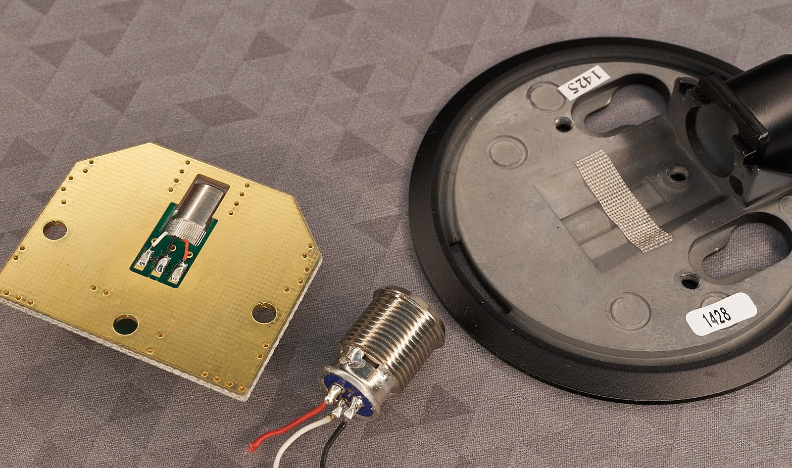
Pulling it apart further (there’s a grub screw which holds the mini XLR connector in place, and it needs to be desoldered to remove the PCB. You can see the electret element has three wires, which suggests it contains an internal amplifier.
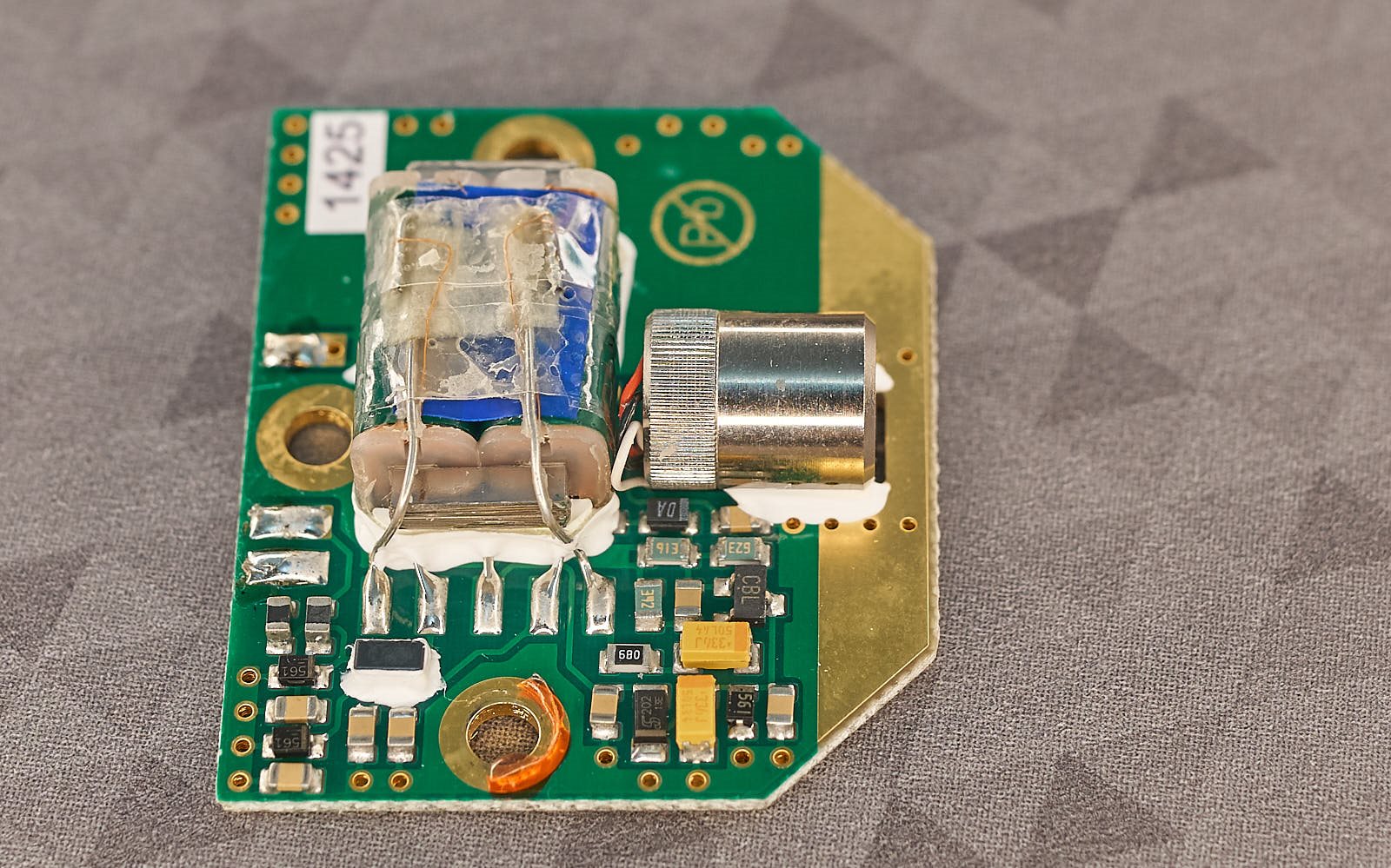
Here’s a closeup of the circuit board, with the green tape removed; now it’s clear that was hiding a transformer.
In the photo below, the board area can be split into three portions; the lower-left contains circuitry for filtering off RF interference arriving via the microphone cable, the center houses the transformer for constructing a balanced output, and the lower-right contains the audio amplifier.
I tried reverse-engineering the circuit (without destroying it, hence I’m sure I have some of this wrong – and all of the non-polarized capacitor values are placeholder guesses).

I’m not sure what D1 is, it has a DA inscription. With some thought, the black component inscribed DA must be a capacitor. Edit: now measured out-of-circuit, it is a 100 nF capacitor.
D5/6/7 are guesses (they have a 561 inscription (Edit: see comments below, D6/7 are most likely 56V zener diodes), they may be 5.6V Zener diodes (although I was under the impression this mic supported a far higher phantom voltage input, so either I am mistaken about the part, or this mic may be a slightly different variant). Edit: D5 is possibly 5.6V zener.
I can’t say I really understand what’s going on with the transformer input and please don’t assume I drew the circuit layout correctly. If you have suggestions/corrections, please let me know. I do intend to fire it up and feed in a signal in place of the mic element and take some measurements one day, but finding time is hard. Funnily enough, I've been thinking about constructing a microphone simulator (but for digital mics).
Any help would be appreciated. Thanks for reading!

