


Table of Contents
Introduction
I’ve rarely encountered RISC-V devices so far, but I was quite interested in checking out the CH32V003 microcontroller for simple, small applications because it is low-cost (25 pence or cents!), has a usable amount of storage (16Kbytes) and pretty reasonable set of basic peripherals! It’s a no-nonsense, straightforward microcontroller, and it doesn’t need anything more than a single decoupling capacitor to function.
This blog post discusses my first attempt at getting going with the CH32V003, covers a brief overview of the microcontroller and development environment, and how to build a custom board and perform some basic operations, specifically GPIO input/output, UART input/output, and experimenting with the Standby mode to see what the current consumption is.
Microcontroller Overview
The diagram below indicates what the microcontroller contains! For more details, check out the datasheet and reference manual.
It comes in four different packages, ranging from an 8-pin device, up to 20-pin. All pins apart from the supply and ground pins can be used as GPIO, meaning up to 18 pins of GPIO are possible.

All the alternate functions for the GPIO pins can be easily controlled by a single 32-bit register called AFIO_PCFR1. All external interrupts can be enabled using a register called AFIO_EXTICR.
The CH32V003 operates from 2.8V to 5.5V, and current consumption ranges from up to 8mA (every peripheral enabled, and at 48 MHz clock speed) down to 400uA in a 750 kHz sleep mode (peripheral clocks can run), and 11uA in standby (no clocks running, but GPIO pin interrupts are available to wake up the device).
The CPU core runs an instruction set called RV32EC, which apparently means embedded integer capabilities and compressed instructions (ability to reduce instructions to 16 bits instead of 32 bits, where feasible). I believe the instruction set can be found here.
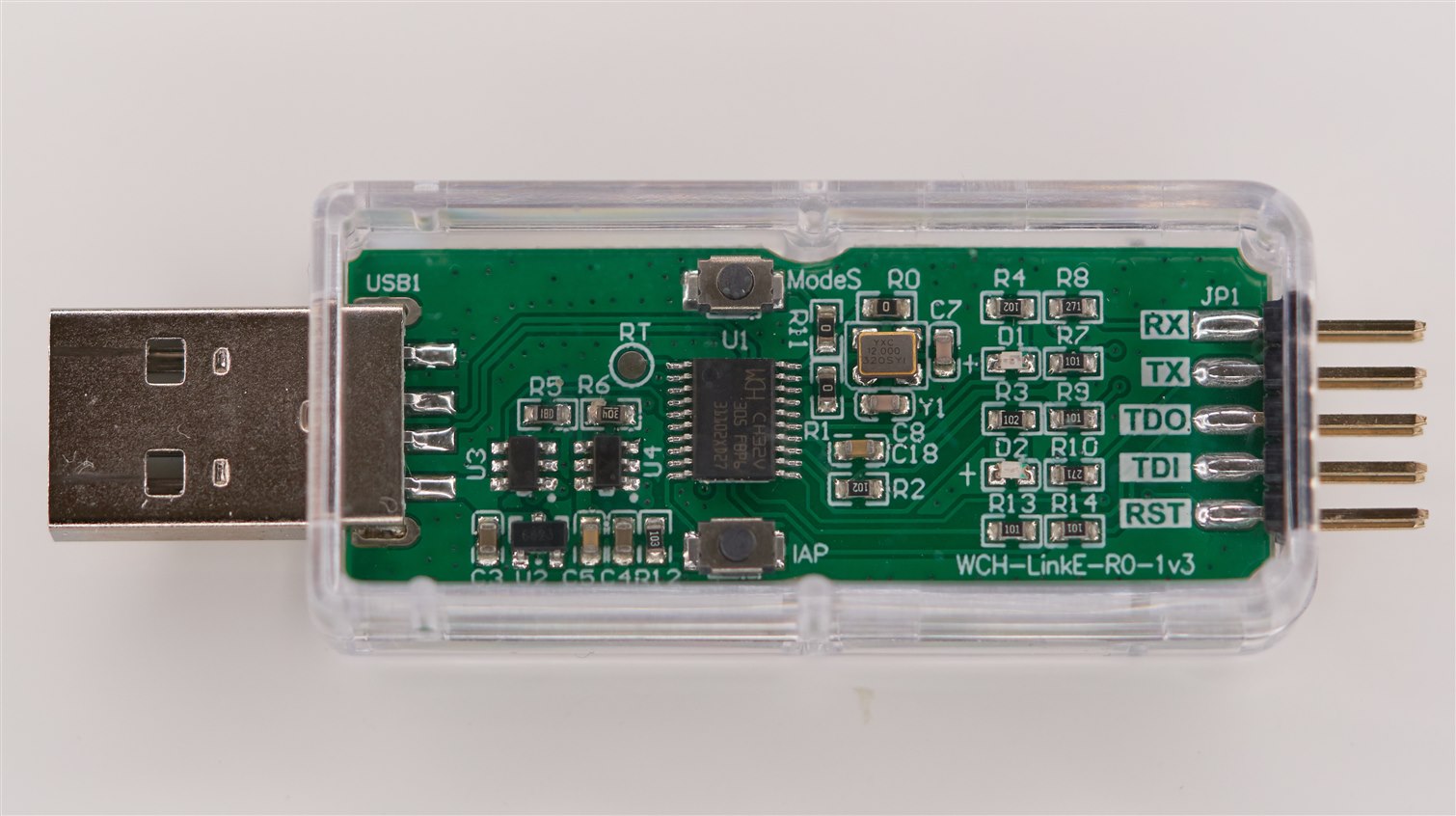
The microcontroller is programmed using just a single wire called SWIO. The USB programmer is low-cost, called WCH-LinkE. In reality, it is useful to dedicate two wires to the programmer, the other being either the *RST connection on the microcontroller, or the supply (VCC). Either *RST, or control of the supply voltage can allow the programmer to initiate programming. By default, all pins other than SWIO, *RST, VCC and GND pins are GPIO. The *RST pin can be set to GPIO mode by configuring an area of Flash, which can be done by the programming tool, or from the code running on the microcontroller.
What’s Needed to Get Started?
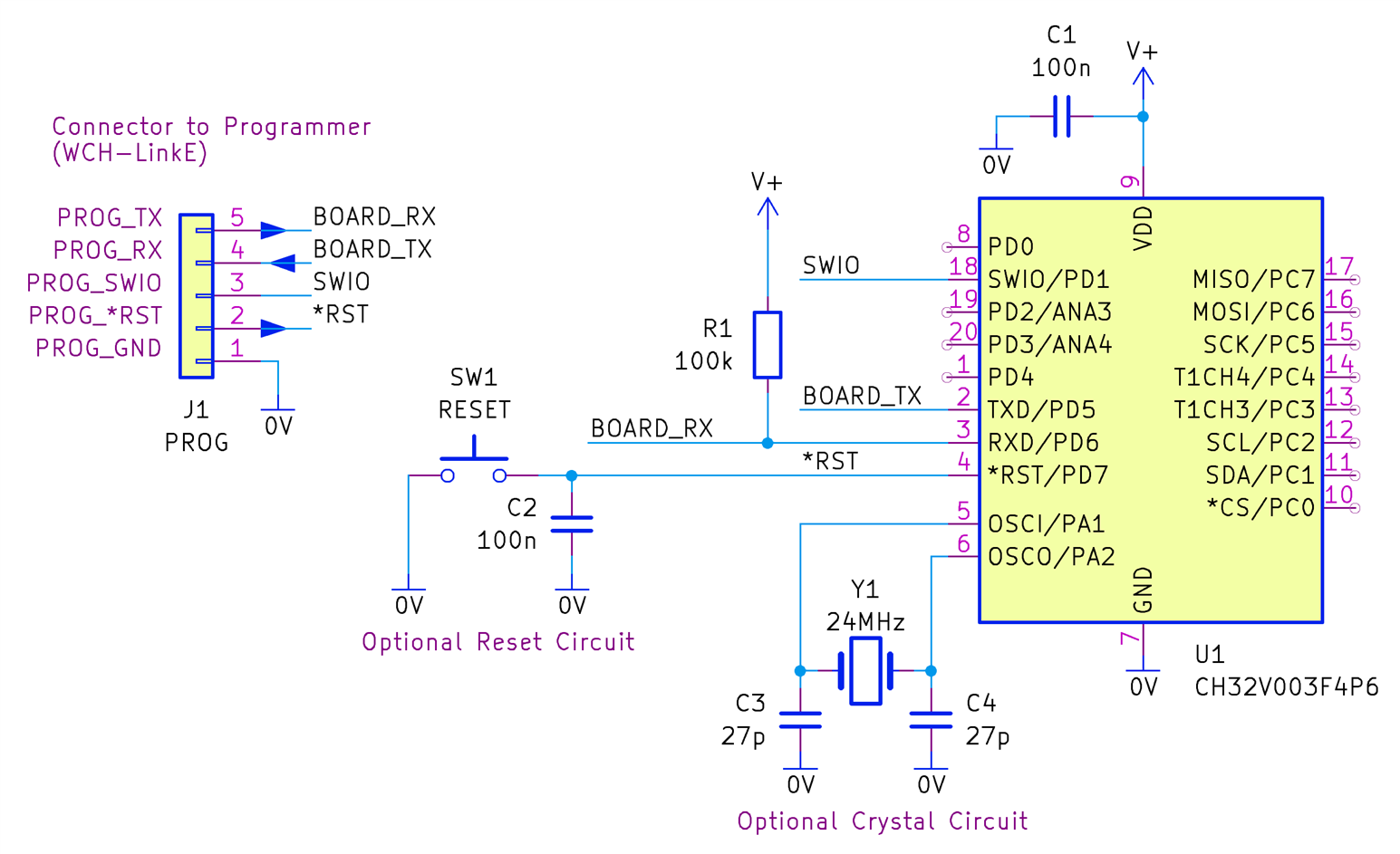
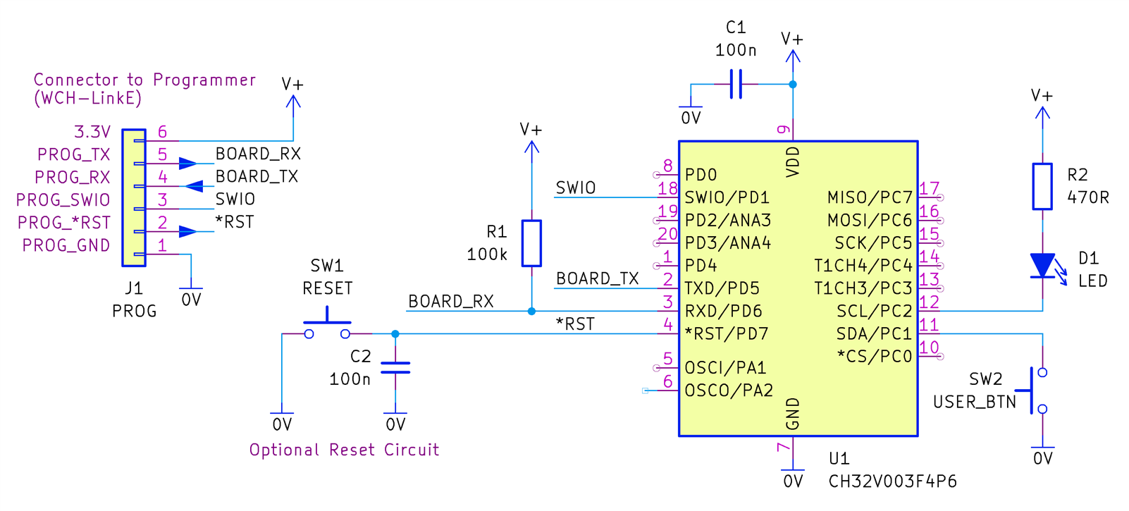
I purchased several TSSOP-20 packaged CH32V003 chips. Their part code is CH32V003F4P6. There’s a 20-pin QFN package version called that replaces the P6 suffix with U6. If you’re not comfortable with TSSOP or QFN, there is a SOIC-16 variant, called CH32V003A4M6. As mentioned earlier, the microcontroller doesn’t need a lot of external circuitry! The circuit diagram below shows the TSSOP-20 package variant. If you’re using a different package, the pin numbering will differ (refer to the datasheet).
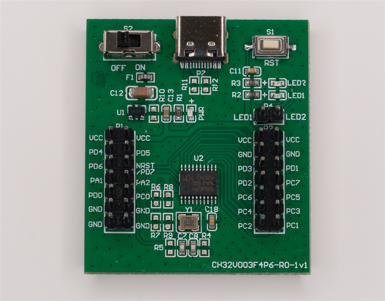
Despite purchasing some chips, to start off with, it’s probably best to pick up a small evaluation board since they are cheap. I obtained an eval board called CH32V003F4P6-EVT-R0.
Plus, importantly, a USB programmer tool called WCH-LinkE is required.
Everything, including five TSSOP-20 chips, all cost about $12/£12.
Development Environment
There are several development environments for the CV32V003. For now, I only tried the manufacturer-suggested one, called MounRiver Studio.
It is based on Eclipse, which means there is some familiarity for developers.
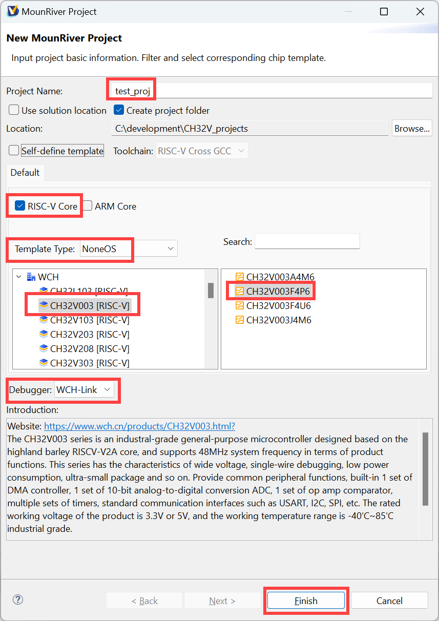
Once the software is installed (it only seems to be available for Windows, but there are other googleable open-source options available for Linux and Mac users), it can be started, and then File->New->MounRiver Project can be selected.
The window is populated as shown below, to select the microcontroller. Note that the Project Name needs to be set last because each time you modify the microcontroller selection, the project name defaults back to match the microcontroller name.
The main MounRiver Studio window view looks as shown below. In Eclipse terminology, it is known as the Code or Develop Perspective.
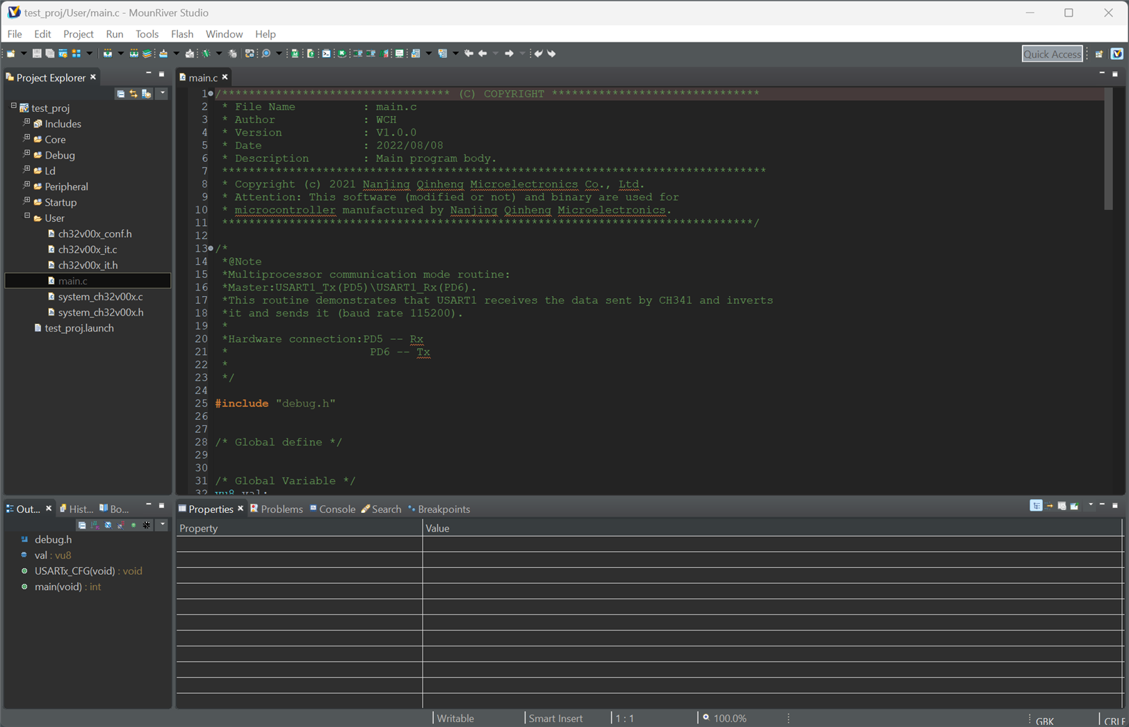
(The view looks different when running your code, it is then called a Debug Perspective).
The most important icons are indicated below.
![]()
In normal development, you’ll click on Build Project (F7) to compile the code, and then click on the Debug icon (Run->Debug from the menu). The view style or Perspective can be selected from the right side, but generally, you don’t need to use the Perspective buttons often because Eclipse will automatically toggle the views between when debugging and when debugging has ended.
Editing the Default Code
The newly created project will contain default code. From the left side Project Explorer, expand the User folder, and double-click on main.c to have it appear in the coding pane. The default code reads data from the UART in the microcontroller, inverts the bits, and sends it back out of the UART.
I changed the line:
USART_SendData(USART1, ~val);
to:
USART_SendData(USART1, val+1);
Now, the UART should send back a character one ASCII code higher than what is typed by the user. Save the file (Ctrl+S), and then move on to the next section!
Building (Compiling) the Code
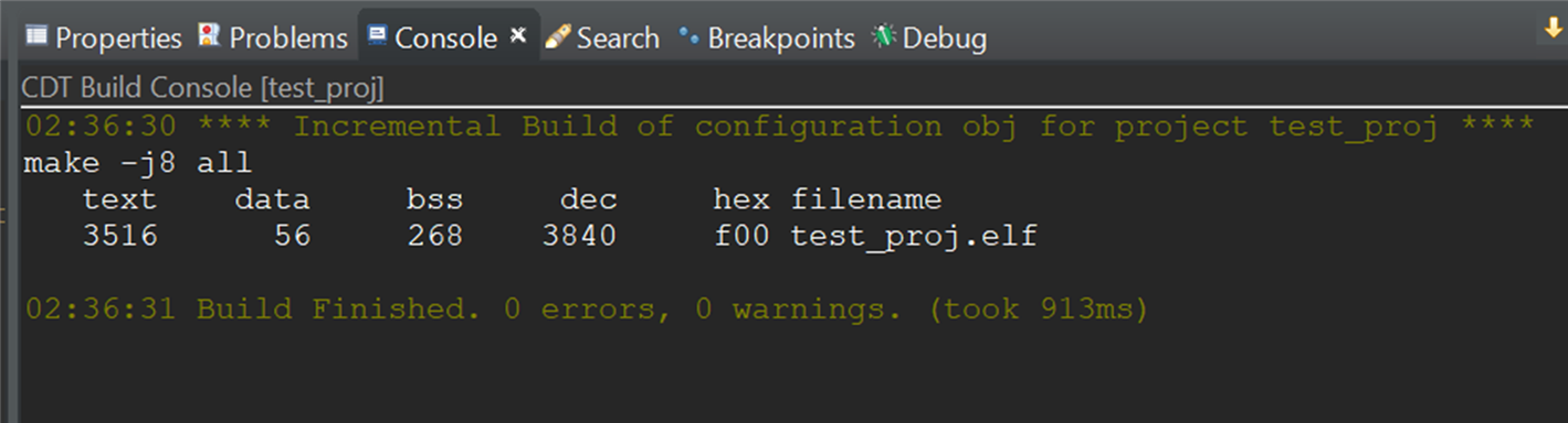
Click on the Build Project (F7) icon. The project will be compiled, and the result will be displayed in the Console tab in the lower pane.
Running the Code
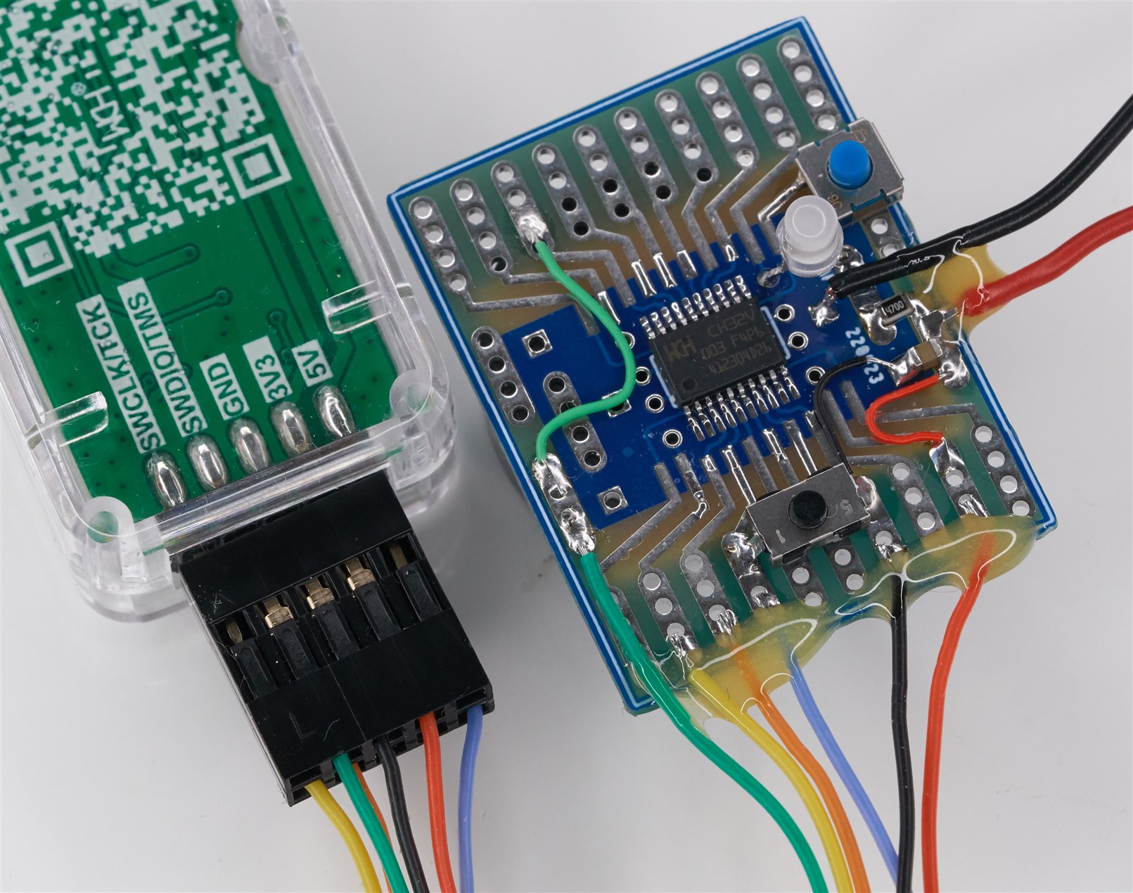
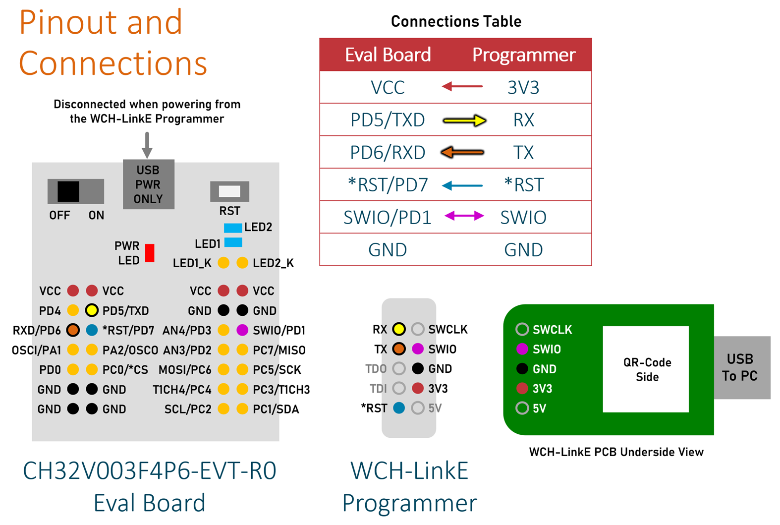
Connect up the WCH-LinkE programmer to the evaluation board as shown below. There’s no need to power up the evaluation board via USB, because it will derive its power from the WCH-LinkE programmer.
Plug the USB cable into the PC, and then click on the Debug button (Run->Debug in the menu). When that’s clicked, the Debug Perspective will be displayed:
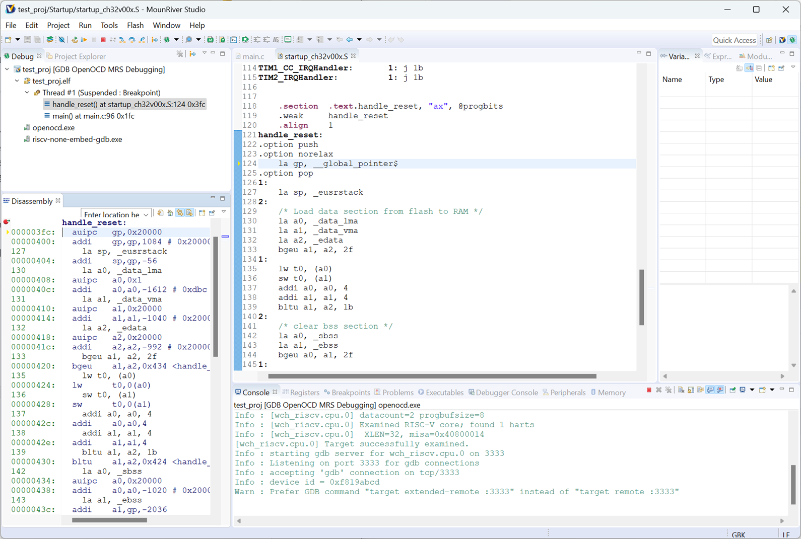
The important icons are shown in the screenshot below.
Since the example project makes use of the UART, you can open a serial console using your preferred software (such as PuTTY), or you can click on the Open Terminal icon and select the available COM port presented by the WCH-LinkE programmer, and select 115200 baud. A terminal tab will appear at the bottom pane.
![]()
Click on the Run icon, and the Terminal tab should show the following content:
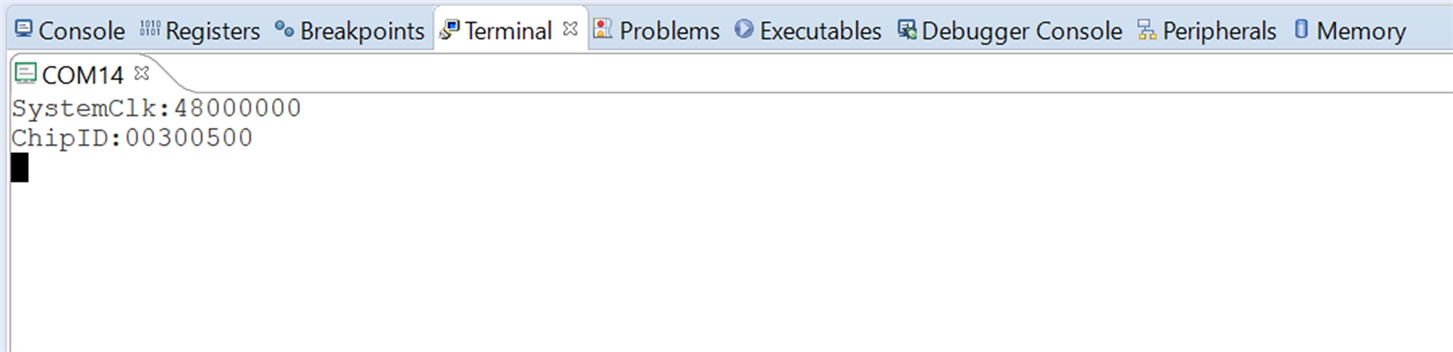
Now press any alphanumeric key, and the console should display an ASCII character one value up!
The code is now incidentally in Flash, so the debugging procedure also resulted in programming the microcontroller.
Afterward, click on the Terminate icon, and the original Code (Develop) Perspective will appear again, all ready for more coding as desired.
Build Your Own Board
The CH32V003 needs no additional components other than a decoupling capacitor to function, although adding the optional reset circuit (button plus capacitor) is highly recommended.

The circuit diagram shown here was assembled.
Coding
Now that the custom board was assembled, it was time to explore coding a bit more! The following sections indicate code snippets for the custom board. The full code is available here. The snippets below are from the main.c file.
General Purpose Input/Output (GPIO)
To configure an input, the following three lines of code are needed; this example configures GPIO PC1 to be an input with pull-up (IPU).
GPIO_InitStructure.GPIO_Pin = GPIO_Pin_1;GPIO_InitStructure.GPIO_Mode = GPIO_Mode_IPU;GPIO_Init(GPIOC, &GPIO_InitStructure);
An output is configured in a near-similar way; outputs have a speed setting (2/10/50 MHz).
GPIO_InitStructure.GPIO_Pin = GPIO_Pin_2;GPIO_InitStructure.GPIO_Mode = GPIO_Mode_Out_PP;GPIO_InitStructure.GPIO_Speed = GPIO_Speed_2MHz;GPIO_Init(GPIOC, &GPIO_InitStructure);
It’s easiest to create defines to use the inputs/outputs:
// LED control (low = LED off, high = LED on)#define LED_OFF GPIO_SetBits(GPIOC, GPIO_Pin_2)#define LED_ON GPIO_ResetBits(GPIOC, GPIO_Pin_2)// button pressed is active low#define BUTTON_PRESSED (GPIO_ReadInputDataBit(GPIOC, GPIO_Pin_1) == 0)#define BUTTON_UNPRESSED (GPIO_ReadInputDataBit(GPIOC, GPIO_Pin_1) != 0)
UART Output (print statements)
The UART is highly useful for outputting debug statements. It is very easy to enable it:
USART_Printf_Init(115200); // this enables the use of print()
After that is done, normal printf() function calls are used to send data to any connected serial console.
UART Input
If you wish to use the UART for both input and output, then a bit more code is needed, to configure the UART more fully. See the code function uart_config_rxtx().
The UART input character buffer can be checked and read at any time using:
uint16_t ch;if (USART_GetFlagStatus(USART1, USART_FLAG_RXNE) == SET) { ch = USART_ReceiveData(USART1); val = (uint8_t)(ch & 0xFF); // val contains the received character}
The above code does not wait, so one could place the USART_GetFlagStatus function in a loop, waiting for a character to arrive if desired.
Sample Code
There is lots of example code available in a CH32V003 Example Software Routines bundle.
├───ADC
│   ├───ADC_DMA
│   │   └───User
│   ├───AnalogWatchdog
│   │   └───User
│   ├───Auto_Injection
│   │   └───User
│   ├───Discontinuous_mode
│   │   └───User
│   ├───ExtLines_Trigger
│   │   └───User
│   └───TIM_Trigger
│       └───User
├───APPLICATION
│   └───SoftUART
│       └───User
├───DMA
│   ├───DMA_MEM2MEM
│   │   └───User
│   └───DMA_MEM2PERIP
├───EXTI
│   └───EXTI0
│       └───User
├───FLASH
│   ├───BootAsUser
│   │   ├───Ld
│   │   ├───Startup
│   │   └───User
│   └───FLASH_Program
│       └───User
├───GPIO
│   └───GPIO_Toggle
│       └───User
├───I2C
│   ├───I2C_10bit_Mode
│   │   └───User
│   ├───I2C_7bit_Mode
│   │   └───User
│   ├───I2C_DMA
│   │   └───User
│   ├───I2C_EEPROM
│   │   └───User
│   └───I2C_PEC
│       └───User
├───IAP
│   └───V00x_APP
│       └───User
├───IWDG
│   └───IWDG
│       └───User
├───OPA
│   └───OPA
│       └───User
├───PWR
│   ├───Sleep_Mode
│   │   └───User
│   └───Standby_Mode
│       └───User
├───RCC
│   ├───Get_CLK
│   │   └───User
│   └───MCO
│       └───User
├───SDI_Printf
│   └───SDI_Printf
│       └───User
├───SPI
│   ├───1Lines_half-duplex
│   │   └───User
│   ├───2Lines_FullDuplex
│   │   └───User
│   ├───FullDuplex_HardNSS
│   │   └───User
│   ├───SPI_CRC
│   │   └───User
│   └───SPI_DMA
│       └───User
├───SRC
│   ├───Core
│   ├───Debug
│   ├───Ld
│   ├───Peripheral
│   │   ├───inc
│   │   └───src
│   └───Startup
├───SYSTICK
│   └───SYSTICK_Interrupt
│       └───User
├───TIM
│   ├───Clock_Select
│   │   └───User
│   ├───ComplementaryOutput_DeadTime
│   │   └───User
│   ├───ExtTrigger_Start_Two_Timer
│   │   └───User
│   ├───Input_Capture
│   │   └───User
│   ├───One_Pulse
│   │   └───User
│   ├───Output_Compare_Mode
│   │   └───User
│   ├───PWM_Output
│   │   └───User
│   ├───Synchro_ExtTrigger
│   │   └───User
│   ├───Synchro_Timer
│   │   └───User
│   └───TIM_DMA
│       └───User
├───USART
│   ├───USART_DMA
│   │   └───User
│   ├───USART_HalfDuplex
│   │   └───User
│   ├───USART_HardwareFlowControl
│   │   └───User
│   ├───USART_Interrupt
│   │   └───User
│   ├───USART_MultiProcessorCommunication
│   │   └───User
│   ├───USART_Polling
│   │   └───User
│   ├───USART_Printf
│   │   └───User
│   └───USART_SynchronousMode
│       └───User
├───USART_IAP
│   ├───CH32V003_APP
│   │   └───User
│   └───CH32V003_IAP
│       ├───Ld
│       └───User
└───WWDG
    └───WWDG
        └───User
Standby Mode
I was interested to see if the standby current consumption was 11uA or not. Test code was written to exercise the GPIO, UART and Standby mode. The code doesn’t have a practical purpose. All it does is (in Standby mode) wait for the user to press a button connected to GPIO PC1. When that occurs, the microcontroller wakes up and turns on an LED for one second, and goes into Standby again. During the time the LED is turned on, the UART output will display any character that the (single byte) UART receive buffer contains.
After the code was built and uploaded to the board (by using the Debug button in the development environment as before), I disconnected the board from the programmer and powered it from three AAA batteries for a 4.5V power source and measured the current consumption.
I could see the current reach 7 mA or so with the LED lit, and then when Standby mode was entered, the current consumption would drop to 10-11uA, so that was a success. See the code to see how to set up the ability to wake up on GPIO input and how to enter the Standby mode.
Note that to achieve 10uA, it is important to set all unused GPIO to inputs with pull-ups. If you’ve configured the UART but no serial console might be connected, then a pull-up resistor on the UART receive pin may be worthwhile adding, as shown in the circuit diagram.
Problems Connecting after Programming?
There can be a risk that if the SWIO pin is configured to an input or output, then it might not be possible for the debugger to be able ever to connect again! There are a few solutions, such as never using the SWIO pin. Another option is to place a short delay in the code prior to configuring any GPIO. Then, if it is not possible for the debugger to connect due to GPIO configuration, it is possible to press the reset button and then quickly press the Debug button in the development environment, and the debugger will be able to connect during the delay. In production code, this could then be removed if there is no need for the debugger ever to be connected again.
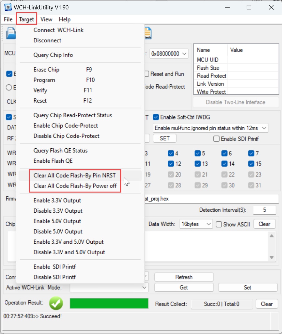
Still Problems Connecting?
Another option could be to try running software called WCH-LinkUtility, which is in the installed MounRiver\MounRiver_Studio\ExTool\SWDTool folder. Try the Target->Clear All Code options.
Summary
The CH32V003 is an interesting, cheap microcontroller that was fairly straightforward to program. There doesn’t seem to be standalone documentation for the library code, but the code is well documented, and it doesn’t take too long to figure out what’s what, especially because the registers are not very complicated. Besides, the CH32V003 is very popular, so it is possible to google for information when one gets stuck.
The microcontroller needs very few parts to get going and is available in hand-solder-friendly packages ranging from the large SOIC-16 down to TSSOP-20 and QFN-20. There is also an 8-pin SOIC-8 version.
Example code was written and it confirmed that it was not too difficult to enter and exit the Standby mode.
It is possible during development to accidentally end up in a situation where the USB programmer tool cannot connect if there is a GPIO pin clash, but a workaround was found, which involves having a reset button on the board and deliberately coding in a short (2-second) delay before GPIO configuration.
If you have any ideas for potential applications for this microcontroller, it would be great to hear them.
Thanks for reading!
Top Comments