element14 Community
element14 Community
    Register Log In
  • Site
  • Search
  • Log In Register
  • About Us
  • Community Hub
    Community Hub
    • What's New on element14
    • Feedback and Support
    • Benefits of Membership
    • Personal Blogs
    • Members Area
    • Achievement Levels
  • Learn
    Learn
    • Ask an Expert
    • eBooks
    • element14 presents
    • Learning Center
    • Tech Spotlight
    • STEM Academy
    • Webinars, Training and Events
    • Learning Groups
  • Technologies
    Technologies
    • 3D Printing
    • FPGA
    • Industrial Automation
    • Internet of Things
    • Power & Energy
    • Sensors
    • Technology Groups
  • Challenges & Projects
    Challenges & Projects
    • Design Challenges
    • element14 presents Projects
    • Project14
    • Arduino Projects
    • Raspberry Pi Projects
    • Project Groups
  • Products
    Products
    • Arduino
    • Avnet Boards Community
    • Dev Tools
    • Manufacturers
    • Multicomp Pro
    • Product Groups
    • Raspberry Pi
    • RoadTests & Reviews
  • Store
    Store
    • Visit Your Store
    • Choose another store...
      • Europe
      •  Austria (German)
      •  Belgium (Dutch, French)
      •  Bulgaria (Bulgarian)
      •  Czech Republic (Czech)
      •  Denmark (Danish)
      •  Estonia (Estonian)
      •  Finland (Finnish)
      •  France (French)
      •  Germany (German)
      •  Hungary (Hungarian)
      •  Ireland
      •  Israel
      •  Italy (Italian)
      •  Latvia (Latvian)
      •  
      •  Lithuania (Lithuanian)
      •  Netherlands (Dutch)
      •  Norway (Norwegian)
      •  Poland (Polish)
      •  Portugal (Portuguese)
      •  Romania (Romanian)
      •  Russia (Russian)
      •  Slovakia (Slovak)
      •  Slovenia (Slovenian)
      •  Spain (Spanish)
      •  Sweden (Swedish)
      •  Switzerland(German, French)
      •  Turkey (Turkish)
      •  United Kingdom
      • Asia Pacific
      •  Australia
      •  China
      •  Hong Kong
      •  India
      •  Korea (Korean)
      •  Malaysia
      •  New Zealand
      •  Philippines
      •  Singapore
      •  Taiwan
      •  Thailand (Thai)
      • Americas
      •  Brazil (Portuguese)
      •  Canada
      •  Mexico (Spanish)
      •  United States
      Can't find the country/region you're looking for? Visit our export site or find a local distributor.
  • Translate
  • Profile
  • Settings
Embedded and Microcontrollers
  • Technologies
  • More
Embedded and Microcontrollers
Blog PID temperature controller for the EasyL1105 MSPM0 board - Pt. 2: ADC
  • Blog
  • Forum
  • Documents
  • Quiz
  • Polls
  • Files
  • Members
  • Mentions
  • Sub-Groups
  • Tags
  • More
  • Cancel
  • New
Join Embedded and Microcontrollers to participate - click to join for free!
  • Share
  • More
  • Cancel
Group Actions
  • Group RSS
  • More
  • Cancel
Engagement
  • Author Author: Jan Cumps
  • Date Created: 27 Sep 2025 7:46 PM Date Created
  • Views 295 views
  • Likes 7 likes
  • Comments 6 comments
  • MSPM0L1105
  • MSPM0
  • easyL1105
  • pid
Related
Recommended

PID temperature controller for the EasyL1105 MSPM0 board - Pt. 2: ADC

Jan Cumps
Jan Cumps
27 Sep 2025

 shabaz designed a development kit for the recent Texas Instruments MSPM0 microcontroller series. 
This 4 part blog series documents the steps to design a PID temperature controller. Part 2: add ADC to sample the temperature sensor

image
(post that introduces the kit)

Goal of this 2nd post

  • add single ADC conversion logic, based on TI adc12_single_conversion
  • use ADC hardware to return value in same Q16 format used in the PID library

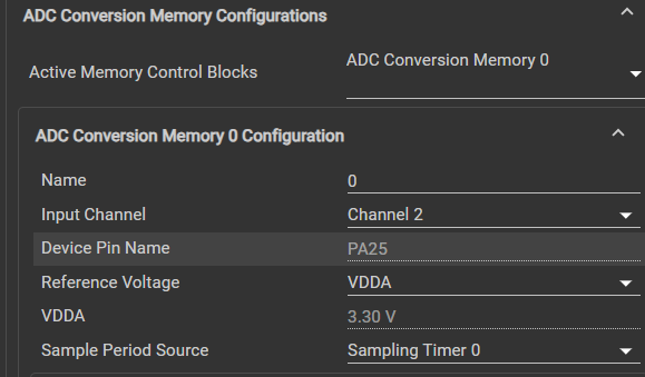
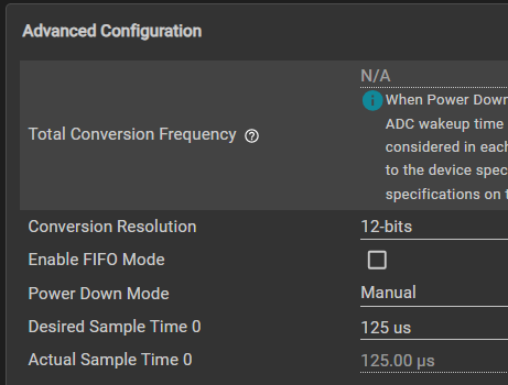
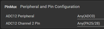
Set up ADC SysConfig

image

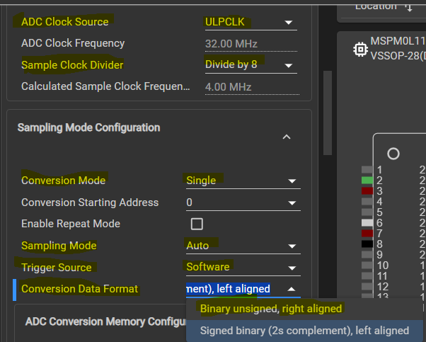
The Conversion Data Format, 2s complement, left aligned, happens to be the same Q15 format that our PID library uses.

image

image

image

image

Code adaption from post 1:

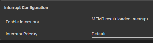
I use a flag to check if sampling is done. The Result Loaded trigger will set that flag.

volatile bool gCheckADC;
uint32_t gAdcResult;

// ...

void ADC12_0_INST_IRQHandler(void) {
    switch (DL_ADC12_getPendingInterrupt(ADC12_0_INST)) {
        case DL_ADC12_IIDX_MEM0_RESULT_LOADED:
            gCheckADC = true;
            break;
        default:
            break;
    }
}

In main(), the IRQ gets enabled

int main(void) {
    SYSCFG_DL_init();

    // ...

    NVIC_EnableIRQ(ADC12_0_INST_INT_IRQN);
    gCheckADC = false;
    
    // ...

The perform_adc() placeholder that I wrote in the 1st post, gets implemented now:

void perform_adc() {
    DL_ADC12_startConversion(ADC12_0_INST);

    while (false == gCheckADC) {
        __WFE();
    }

    gAdcResult = (uint32_t)DL_ADC12_getMemResult(ADC12_0_INST, DL_ADC12_MEM_IDX_0);

    gCheckADC = false;
    DL_ADC12_enableConversions(ADC12_0_INST);
}

I could make gAdcResult a return value instead of a global variable. Maybe later ...

Thanks for reading. Next, get PWM working.

ccs project for EasyL1105: pid_EasyL1105_20250927.zip

Related posts

  • Sign in to reply
Parents
  • shabaz
    shabaz 9 hours ago

    Made a bit more progress over the weekend.. still not attached the MOSFET circuit, but figured a little display could be useful. It's optional, the code will continue to run if it's missing of course.

    The photo shows the result, the screen is really small (0.85"), but on the plus side it's super-cheap ($2) and, since just a few digits are being displayed, the main values are visible from at least a couple of meters away.

    If anyone wants this exact screen, it is BuyDisplay ER-TFT0.85-1  and has 128x128 resolution. The supplied code wasn't ideal, but I've modified it slightly, and now it works fine with the MSPM0 chip (and can be used with any microcontroller supporting SPI). To keep ROM usage low I've only implemented Hershey font with ASCII characters " " to "Z", no lower-case text. (Font ROM usage is about 1600 bytes which is approx. 5% of total ROM, could be optimized further).

    Using it is easy in the code (for the photo below, I used these lines):

        // tft test
        lcd_Initial();
        USE_HORIZONTAL=0;
        ClearScreen(0x0000);	// black
    
        drawText("ACTUAL DEG C", 5, 25, 0.5f, 0.8f, PEN_THIN, YELLOW);
        drawText("257.9", 2, 80, 1.4f, 2.0f, PEN_THICK, YELLOW);
        drawText("SET: 250.0", 10, 125, 0.6f, 1.0f, PEN_THIN, CYAN);

    image

    Physically, these are the connections I made:

    GPIO   TFT_LABEL          EASYL1105_LABEL   MyWireCol
    -----  ----------------   ---------------   ---------
    PA4  : TFT_RESET          Labeled MISO      BLUE
    PA6  : TFT_SCL (CLOCK)    Labeled SCK       YELLOW
    PA5  : TFT_SDA (DATA)     Labeled MOSI      GREEN
    PA3  : TFT_CS             Labeled CS1       PINK
    PA24 : TFT_D/C            Labeled CS2       PURPLE
         : VDD                3.3V              RED
         : GND                GND               BLACK
           LED_A              3.3V via 10-ohm
           LED_K              GND               BLACK
    

    Also through implementing it, I discovered a bug with the MSPM0 Python programmer, it's now fixed on GitHub.

    The code I'm using is here:

    pid_EasyL1105_with_tft.zip

    • Cancel
    • Vote Up 0 Vote Down
    • Sign in to reply
    • More
    • Cancel
Comment
  • shabaz
    shabaz 9 hours ago

    Made a bit more progress over the weekend.. still not attached the MOSFET circuit, but figured a little display could be useful. It's optional, the code will continue to run if it's missing of course.

    The photo shows the result, the screen is really small (0.85"), but on the plus side it's super-cheap ($2) and, since just a few digits are being displayed, the main values are visible from at least a couple of meters away.

    If anyone wants this exact screen, it is BuyDisplay ER-TFT0.85-1  and has 128x128 resolution. The supplied code wasn't ideal, but I've modified it slightly, and now it works fine with the MSPM0 chip (and can be used with any microcontroller supporting SPI). To keep ROM usage low I've only implemented Hershey font with ASCII characters " " to "Z", no lower-case text. (Font ROM usage is about 1600 bytes which is approx. 5% of total ROM, could be optimized further).

    Using it is easy in the code (for the photo below, I used these lines):

        // tft test
        lcd_Initial();
        USE_HORIZONTAL=0;
        ClearScreen(0x0000);	// black
    
        drawText("ACTUAL DEG C", 5, 25, 0.5f, 0.8f, PEN_THIN, YELLOW);
        drawText("257.9", 2, 80, 1.4f, 2.0f, PEN_THICK, YELLOW);
        drawText("SET: 250.0", 10, 125, 0.6f, 1.0f, PEN_THIN, CYAN);

    image

    Physically, these are the connections I made:

    GPIO   TFT_LABEL          EASYL1105_LABEL   MyWireCol
    -----  ----------------   ---------------   ---------
    PA4  : TFT_RESET          Labeled MISO      BLUE
    PA6  : TFT_SCL (CLOCK)    Labeled SCK       YELLOW
    PA5  : TFT_SDA (DATA)     Labeled MOSI      GREEN
    PA3  : TFT_CS             Labeled CS1       PINK
    PA24 : TFT_D/C            Labeled CS2       PURPLE
         : VDD                3.3V              RED
         : GND                GND               BLACK
           LED_A              3.3V via 10-ohm
           LED_K              GND               BLACK
    

    Also through implementing it, I discovered a bug with the MSPM0 Python programmer, it's now fixed on GitHub.

    The code I'm using is here:

    pid_EasyL1105_with_tft.zip

    • Cancel
    • Vote Up 0 Vote Down
    • Sign in to reply
    • More
    • Cancel
Children
No Data
element14 Community

element14 is the first online community specifically for engineers. Connect with your peers and get expert answers to your questions.

  • Members
  • Learn
  • Technologies
  • Challenges & Projects
  • Products
  • Store
  • About Us
  • Feedback & Support
  • FAQs
  • Terms of Use
  • Privacy Policy
  • Legal and Copyright Notices
  • Sitemap
  • Cookies

An Avnet Company © 2025 Premier Farnell Limited. All Rights Reserved.

Premier Farnell Ltd, registered in England and Wales (no 00876412), registered office: Farnell House, Forge Lane, Leeds LS12 2NE.

ICP 备案号 10220084.

Follow element14

  • X
  • Facebook
  • linkedin
  • YouTube