element14 Community
element14 Community
    Register Log In
  • Site
  • Search
  • Log In Register
  • Community Hub
    Community Hub
    • What's New on element14
    • Feedback and Support
    • Benefits of Membership
    • Personal Blogs
    • Members Area
    • Achievement Levels
  • Learn
    Learn
    • Ask an Expert
    • eBooks
    • element14 presents
    • Learning Center
    • Tech Spotlight
    • STEM Academy
    • Webinars, Training and Events
    • Learning Groups
  • Technologies
    Technologies
    • 3D Printing
    • FPGA
    • Industrial Automation
    • Internet of Things
    • Power & Energy
    • Sensors
    • Technology Groups
  • Challenges & Projects
    Challenges & Projects
    • Design Challenges
    • element14 presents Projects
    • Project14
    • Arduino Projects
    • Raspberry Pi Projects
    • Project Groups
  • Products
    Products
    • Arduino
    • Avnet & Tria Boards Community
    • Dev Tools
    • Manufacturers
    • Multicomp Pro
    • Product Groups
    • Raspberry Pi
    • RoadTests & Reviews
  • About Us
  • Store
    Store
    • Visit Your Store
    • Choose another store...
      • Europe
      •  Austria (German)
      •  Belgium (Dutch, French)
      •  Bulgaria (Bulgarian)
      •  Czech Republic (Czech)
      •  Denmark (Danish)
      •  Estonia (Estonian)
      •  Finland (Finnish)
      •  France (French)
      •  Germany (German)
      •  Hungary (Hungarian)
      •  Ireland
      •  Israel
      •  Italy (Italian)
      •  Latvia (Latvian)
      •  
      •  Lithuania (Lithuanian)
      •  Netherlands (Dutch)
      •  Norway (Norwegian)
      •  Poland (Polish)
      •  Portugal (Portuguese)
      •  Romania (Romanian)
      •  Russia (Russian)
      •  Slovakia (Slovak)
      •  Slovenia (Slovenian)
      •  Spain (Spanish)
      •  Sweden (Swedish)
      •  Switzerland(German, French)
      •  Turkey (Turkish)
      •  United Kingdom
      • Asia Pacific
      •  Australia
      •  China
      •  Hong Kong
      •  India
      •  Korea (Korean)
      •  Malaysia
      •  New Zealand
      •  Philippines
      •  Singapore
      •  Taiwan
      •  Thailand (Thai)
      • Americas
      •  Brazil (Portuguese)
      •  Canada
      •  Mexico (Spanish)
      •  United States
      Can't find the country/region you're looking for? Visit our export site or find a local distributor.
  • Translate
  • Profile
  • Settings
Embedded and Microcontrollers
  • Technologies
  • More
Embedded and Microcontrollers
Embedded Forum CPLD P-Mosfet Output Circuit - Will it Work?
  • Blog
  • Forum
  • Documents
  • Quiz
  • Polls
  • Files
  • Members
  • Mentions
  • Sub-Groups
  • Tags
  • More
  • Cancel
  • New
Join Embedded and Microcontrollers to participate - click to join for free!
Actions
  • Share
  • More
  • Cancel
Forum Thread Details
  • State Suggested Answer
  • Replies 17 replies
  • Answers 2 answers
  • Subscribers 474 subscribers
  • Views 1745 views
  • Users 0 members are here
  • mosfet
  • cpld
  • altera
  • max_v_cpld
Related

CPLD P-Mosfet Output Circuit - Will it Work?

oldmanraskers
oldmanraskers over 10 years ago

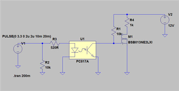
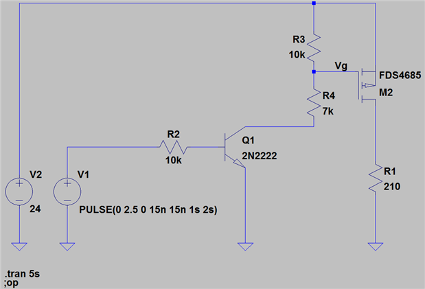
Could someone please offer their opinion on whether my circuit would work well for turning on an output via a CPLD. The output voltage at PIN0 will be 3.3V. I want logic 1 to turn on my Q1.

Regards, oldmanraskers.

Attachments:
image
  • Sign in to reply
  • Cancel

Top Replies

  • jw0752
    jw0752 over 10 years ago +2
    Hi, I set up your circuit on LTSPICE and there are a couple problems. First of all I am assuming that you are putting a load between Vdd and the drain of your MOSFET. Second your choice of IRF9530 will…
  • jw0752
    jw0752 over 10 years ago in reply to oldmanraskers +2 suggested
    Hi oldmanraskers, Here is the SPICE file for the simulation that I ran. If you don't have the LTSpcie program yet just go to the Linear Technologies web site and down load it as it is free. It seems that…
  • jw0752
    jw0752 over 10 years ago +1
    Hi , A little follow-up. Here is a web site that explains how to bias the P Ch MOSFET IRF9530 in case you need to use it. http://www.electronics-tutorials.ws/transistor/tran_6.html Here is an excerpt on…
  • clem57
    0 clem57 over 10 years ago

    A good plan to have  a simulation running the design. Barring that check out MOSFET as a Switch - Using Power MOSFET Switching to determine the various outputs on the P-Mosfet.

    clem

    • Cancel
    • Vote Up 0 Vote Down
    • Sign in to reply
    • Verify Answer
    • Cancel
  • jw0752
    0 jw0752 over 10 years ago

    Hi,

    I set up your circuit on LTSPICE and there are a couple problems. First of all I am assuming that you are putting a load between Vdd and the drain of your MOSFET. Second your choice of IRF9530 will not work. IRF9530 is a P channel Enhanced MOSFET. An N Channel MOSFET like IRF511 will work in your application if the load is between Vdd and the drain of the  MOSFET.


    Here is a schematic:


    image

    If you can run LTSPICE I can send the simulation to you too. Let me know if you hve further questions.


    John

    • Cancel
    • Vote Up +2 Vote Down
    • Sign in to reply
    • Verify Answer
    • Cancel
  • jw0752
    0 jw0752 over 10 years ago

    Hi ,

    A little follow-up. Here is a web site that explains how to bias the P Ch MOSFET IRF9530 in case you need to use it.


    http://www.electronics-tutorials.ws/transistor/tran_6.html


    Here is an excerpt on the P channel specifically. Incidentally this is a great site for basic information.


    image

    From Electronic Tutorials. See Link above


    John

    • Cancel
    • Vote Up +1 Vote Down
    • Sign in to reply
    • Verify Answer
    • Cancel
  • jw0752
    0 jw0752 over 10 years ago in reply to clem57

    Hi Clem,

    Sorry I didn't notice that you had already recommended the Electronic Tutorial website when I posted my follow-up.

    John

    • Cancel
    • Vote Up 0 Vote Down
    • Sign in to reply
    • Verify Answer
    • Cancel
  • michaelkellett
    0 michaelkellett over 10 years ago

    In addition to the comments from others I'll add these:


    1)      When the CPLD powers up or is reset  the output pin will have a default state - you must decide if you want the power switch to be on or off at this point and design the biasing accordingly.


    2)     I'm not sure why you are using an opto isolator to drive the MOSFET - is this really necessary, what is the load you are switching  ?


    3)     Is additional protection of the switching device required, like inductive spike suppression or current limiting ?


    MK

    • Cancel
    • Vote Up 0 Vote Down
    • Sign in to reply
    • Verify Answer
    • Cancel
  • oldmanraskers
    0 oldmanraskers over 10 years ago in reply to jw0752

    Hi John,

    Thanks for the reply - I've never used LTSpice so yeah I'd be interested to see the file. Thanks.

    • Cancel
    • Vote Up 0 Vote Down
    • Sign in to reply
    • Verify Answer
    • Cancel
  • oldmanraskers
    0 oldmanraskers over 10 years ago in reply to michaelkellett

    I'm using the opto because I'm experimenting with stuff, I guess I could use a standard NPN transistor - I am using the circuit to drive small solenoids that will eventually form a lock - they draw about 240mA. It appears to me now, that I have my FET in upside down, and in regards to spike suppression I will need some kind of flywheel diode I think.

    Regards, oldmanraskers.

    • Cancel
    • Vote Up 0 Vote Down
    • Sign in to reply
    • Verify Answer
    • Cancel
  • jw0752
    0 jw0752 over 10 years ago in reply to oldmanraskers

    Hi oldmanraskers,

    Here is the SPICE file for the simulation that I ran. If you don't have the LTSpcie program yet just go to the Linear Technologies web site and down load it as it is free. It seems that I do not know how to give you an executable file in this posting. Here is the bitmap of the circuit that I put into LTSPICE. You can download the program and draw the schematic and run it. Signal Supply V1 is 3.3Volts square wave with 2 uSecond rise and fall time. 10 millisecond Duration and 20 millisecond Period.  Power supply V2 is just 12 Volt DC.


    John


    image

    • Cancel
    • Vote Up +2 Vote Down
    • Sign in to reply
    • Verify Answer
    • Reject Answer
    • Cancel
  • johnbeetem
    0 johnbeetem over 10 years ago in reply to oldmanraskers

    oldmanraskers wrote:


    I'm using the opto because I'm experimenting with stuff, I guess I could use a standard NPN transistor - I am using the circuit to drive small solenoids that will eventually form a lock - they draw about 240mA. It appears to me now, that I have my FET in upside down, and in regards to spike suppression I will need some kind of flywheel diode I think.

    Regards, oldmanraskers.

    For driving that kind of load, I would suggest using NPN Darlington pairs, such as the TI ULN2003A or similar.  Those can sink a lot of current and have built-in flyback diodes.


    To get a lot of current through a FET, you need a gate voltage that's higher (or lower for PFET) than your normal logic voltages.  For example, you get a small IC called a "high side switch" that uses a charge pump to boost the an NFET's gate voltage.

    • Cancel
    • Vote Up +1 Vote Down
    • Sign in to reply
    • Verify Answer
    • Reject Answer
    • Cancel
  • oldmanraskers
    0 oldmanraskers over 10 years ago

    I have looked at my circuit again and come up with this one. The FET is not the exact one that I'm going to use but I think it would do the job regardless. I considered replacing R4 with a Zener but I'm not sure that is really warranted - what do you think? I'm still sticking with MOSFETs just because I obviously don't know enough about them and want to investigate them further. I do have a question regarding R3 though - I have noticed that the larger R3 is made the slower the gate takes to reach the correct voltage - I assume this is capacitance related to the gate, but I don't understand how to decide what values of R3 would cause me problems - any pointers?


    Let me know what you think and thanks for your input thus far.

    Regards, oldmanraskers.

    image

    • Cancel
    • Vote Up 0 Vote Down
    • Sign in to reply
    • Verify Answer
    • Cancel
>
element14 Community

element14 is the first online community specifically for engineers. Connect with your peers and get expert answers to your questions.

  • Members
  • Learn
  • Technologies
  • Challenges & Projects
  • Products
  • Store
  • About Us
  • Feedback & Support
  • FAQs
  • Terms of Use
  • Privacy Policy
  • Legal and Copyright Notices
  • Sitemap
  • Cookies

An Avnet Company © 2025 Premier Farnell Limited. All Rights Reserved.

Premier Farnell Ltd, registered in England and Wales (no 00876412), registered office: Farnell House, Forge Lane, Leeds LS12 2NE.

ICP 备案号 10220084.

Follow element14

  • X
  • Facebook
  • linkedin
  • YouTube