element14 Community
element14 Community
    Register Log In
  • Site
  • Search
  • Log In Register
  • About Us
  • Community Hub
    Community Hub
    • What's New on element14
    • Feedback and Support
    • Benefits of Membership
    • Personal Blogs
    • Members Area
    • Achievement Levels
  • Learn
    Learn
    • Ask an Expert
    • eBooks
    • element14 presents
    • Learning Center
    • Tech Spotlight
    • STEM Academy
    • Webinars, Training and Events
    • Learning Groups
  • Technologies
    Technologies
    • 3D Printing
    • FPGA
    • Industrial Automation
    • Internet of Things
    • Power & Energy
    • Sensors
    • Technology Groups
  • Challenges & Projects
    Challenges & Projects
    • Design Challenges
    • element14 presents Projects
    • Project14
    • Arduino Projects
    • Raspberry Pi Projects
    • Project Groups
  • Products
    Products
    • Arduino
    • Avnet Boards Community
    • Dev Tools
    • Manufacturers
    • Multicomp Pro
    • Product Groups
    • Raspberry Pi
    • RoadTests & Reviews
  • Store
    Store
    • Visit Your Store
    • Choose another store...
      • Europe
      •  Austria (German)
      •  Belgium (Dutch, French)
      •  Bulgaria (Bulgarian)
      •  Czech Republic (Czech)
      •  Denmark (Danish)
      •  Estonia (Estonian)
      •  Finland (Finnish)
      •  France (French)
      •  Germany (German)
      •  Hungary (Hungarian)
      •  Ireland
      •  Israel
      •  Italy (Italian)
      •  Latvia (Latvian)
      •  
      •  Lithuania (Lithuanian)
      •  Netherlands (Dutch)
      •  Norway (Norwegian)
      •  Poland (Polish)
      •  Portugal (Portuguese)
      •  Romania (Romanian)
      •  Russia (Russian)
      •  Slovakia (Slovak)
      •  Slovenia (Slovenian)
      •  Spain (Spanish)
      •  Sweden (Swedish)
      •  Switzerland(German, French)
      •  Turkey (Turkish)
      •  United Kingdom
      • Asia Pacific
      •  Australia
      •  China
      •  Hong Kong
      •  India
      •  Korea (Korean)
      •  Malaysia
      •  New Zealand
      •  Philippines
      •  Singapore
      •  Taiwan
      •  Thailand (Thai)
      • Americas
      •  Brazil (Portuguese)
      •  Canada
      •  Mexico (Spanish)
      •  United States
      Can't find the country/region you're looking for? Visit our export site or find a local distributor.
  • Translate
  • Profile
  • Settings
Experts, Learning and Guidance
  • Technologies
  • More
Experts, Learning and Guidance
Ask an Expert Forum Voltage Doubler Circuit to light a LED with a single AAA battery
  • Blog
  • Forum
  • Documents
  • Leaderboard
  • Files
  • Members
  • Mentions
  • Sub-Groups
  • Tags
  • More
  • Cancel
  • New
Join Experts, Learning and Guidance to participate - click to join for free!
Actions
  • Share
  • More
  • Cancel
Forum Thread Details
  • State Verified Answer
  • Replies 20 replies
  • Answers 12 answers
  • Subscribers 291 subscribers
  • Views 3926 views
  • Users 0 members are here
  • voltage doubler
  • led
  • analog
Related
See a helpful answer?

Be sure to click 'more' and select 'suggest as answer'!

If you're the thread creator, be sure to click 'more' then 'Verify as Answer'!

Voltage Doubler Circuit to light a LED with a single AAA battery

fmilburn
fmilburn over 6 years ago

I told myself this morning if I did not have this solved by tonight myself I would post it on element14  :-) as a Holiday puzzle.  It seems simple enough....


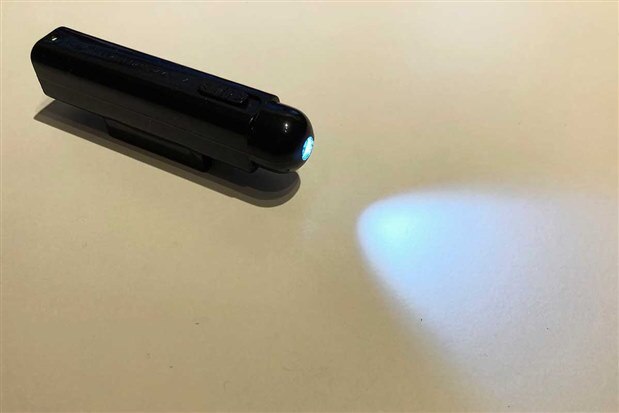
The school my grandson goes to gives out little awards from time to time and he recently selected a "spy kit" as his reward.  Inside was a little flashlight / torch that wasn't working.  Since all spies need a miniature flashlight he asked me to see if I could fix it.  It turned out that it wasn't getting good contact on the positive terminal and was fairly easily fixed.  This is what it looks like working:

image

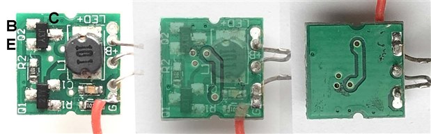
While I had it apart I couldn't help examining it closer.  This is the (very cheap and poorly assembled) PCB.

image

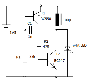
A single AAA battery powers it.  Negative is the red wire and positive is the bare wire coming up between the legs of the LED.  The datasheets for the two SOT-23 transistors (J3Y and 2TY) are online and the two resistors and inductor are marked.  I removed the capacitor and measured 0.5 nF.  Using a multimeter and following the traces in the photo above I came up with this for the schematic.

image


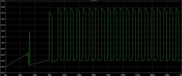
This is what the output to the LED looks like on the oscilloscope:

image

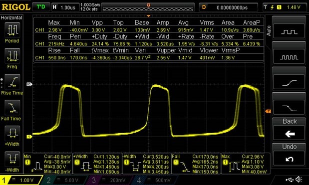
Voltage is doubled from 1.5V input to ~3V peak to peak output and is a rough square wave with duty of 24% on and 76% off.  Frequency is 215 kHZ.  I powered it with the bench supply to see how it behaved as the voltage was lowered and it continued to put out reduced light down to 0.7V input without problem.


I tried simulating the schematic above but only get 1.5V DC output.  I may have missed something when tracing the circuit but if so I missed it again when rechecking.  Or I may not be simulating it correctly / have wrong values somehow.


Having failed to convince myself I understand how it works I have decided to post it here and see what the experts say...

  • Sign in to reply
  • Cancel

Top Replies

  • Gough Lui
    Gough Lui over 6 years ago +6 suggested
    fmilburn - it's a known issue with the site that the images on the first post can't be seen by other members (myself included) due to permissions issues. If you can edit your post by making a trivial change…
  • 14rhb
    14rhb over 6 years ago +6 verified
    Hi Frank, I can see the diagrams OK. It strikes me as a bit strange that TR2 shorts the PSU - are you sure there isn't a connection between the anode of the LED (and inductor/cap) and the collector of…
  • geralds
    geralds over 6 years ago in reply to fmilburn +6 suggested
    Please can you post the second side of the PCB? Than we can better follow the circuit. So I think something is different as you've drawn. Also the value of the cap. may not 500pF, I think it's a bit larger…
Parents
  • gecoz
    0 gecoz over 6 years ago

    Hi Frank,


    I think Jon guess is spot on.


    Looking at the PCB, it looks like is basically a 2 stage amplifier, made with 2 common-emitter stages, in a positive feedback configuration, which creates an oscillator.

    The positive feedback loop is created by C1. I believe your schematic has C1 wrongly positioned: from the PCB picture I would say C1 goes from the collector of the NPN transistor to the base of the PNP one, and so closing the feedback loop.

    Also, I think one end of L1 is connected to the positive supply and the emitter of the PNP, but the other end should be connected to the collector of the NPN and one end of C1. The led is then connected between the collector of the NPN and ground.


    Fabio

    • Cancel
    • Vote Up +5 Vote Down
    • Sign in to reply
    • Verify Answer
    • Reject Answer
    • Cancel
  • fmilburn
    0 fmilburn over 6 years ago in reply to gecoz

    Hi Fabio,


    Did I catch it all in the revised schematic above?

    • Cancel
    • Vote Up +2 Vote Down
    • Sign in to reply
    • Verify Answer
    • Cancel
  • gecoz
    0 gecoz over 6 years ago in reply to fmilburn

    Hi Frank,


    Yes, I think you did. And you definitely are on the right track.


    Also, now qualitatively, you are getting the right results. The difference between the scope observation and the model results could be due to the different values used to characterise the transistors in the model. Did you find use the specific SPICE models for the transistors, or used generic NPN and PNP models?


    Fabio

    • Cancel
    • Vote Up +5 Vote Down
    • Sign in to reply
    • Verify Answer
    • Reject Answer
    • Cancel
Reply
  • gecoz
    0 gecoz over 6 years ago in reply to fmilburn

    Hi Frank,


    Yes, I think you did. And you definitely are on the right track.


    Also, now qualitatively, you are getting the right results. The difference between the scope observation and the model results could be due to the different values used to characterise the transistors in the model. Did you find use the specific SPICE models for the transistors, or used generic NPN and PNP models?


    Fabio

    • Cancel
    • Vote Up +5 Vote Down
    • Sign in to reply
    • Verify Answer
    • Reject Answer
    • Cancel
Children
  • fmilburn
    0 fmilburn over 6 years ago in reply to gecoz

    It has generic values in the SPICE model.  The version I am using has lots of different transistor models but of course not the ones in the circuit.  I did not see an equivalent on the datasheet that was also in the model.  The model parameters are also missing from the datasheet.


    But I think I still have something wrong even without tuning the transistor model.  The output does not return to the original ground which does not make sense to me and the output peak to peak is still 1.5V.

    • Cancel
    • Vote Up +3 Vote Down
    • Sign in to reply
    • Verify Answer
    • Reject Answer
    • Cancel
  • geralds
    0 geralds over 6 years ago in reply to fmilburn

    Please can you post the second side of the PCB?

    Than we can better follow the circuit.

    So I think something is different as you've drawn.

    Also the value of the cap. may not 500pF, I think it's a bit larger so up to few nF.


    I have a similar circuit. Please compare it with yours.

    image

    Thanks


    Best Regards

    Gerald

    ---

    • Cancel
    • Vote Up +6 Vote Down
    • Sign in to reply
    • Verify Answer
    • Reject Answer
    • Cancel
  • gecoz
    0 gecoz over 6 years ago in reply to fmilburn

    Hi Frank,


    Try using some real transistor model for the NPN and PNP instead of the generic ones. The 1.5V peak is probably due to the LED model you are using, changing the LED model (the N parameter in particular) will help you match the scope output where peak voltage is concerned (you can find some info on SPICE LED modelling here).

    As for the output not returning to ground level, this is probably due to the charge/discharge cycle of C1 (I'm assuming that the charge retained by C1 will stop the output to drop down to ground level pushes the NPN transistor into saturation).


    Fabio


    P.S: I put together your circuit using LTSpice, and simulate it, using 2 common transistor models and  creating my own model for the LED. Below you can see my results


    image


    image

    • Cancel
    • Vote Up +4 Vote Down
    • Sign in to reply
    • Verify Answer
    • Reject Answer
    • Cancel
  • fmilburn
    0 fmilburn over 6 years ago in reply to gecoz
    Awesome :-) 
    I much prefer the way you drew it also.  I have been going over it for the last hour or so and have not made any progress.
    • Cancel
    • Vote Up +4 Vote Down
    • Sign in to reply
    • Verify Answer
    • Cancel
  • fmilburn
    0 fmilburn over 6 years ago in reply to geralds

    Hi Gerald,

    It was securely glued to a plastic tab and I was concerned about breaking the fragile PCB but went ahead and did it in the name of science.  I have since managed to get it back together and working.  In the photo below the middle has been mirrored and superimposed as if looking down through the PCB from the top.  Both transistors have the same pin configuration which I have labelled on the left.  The far right is the unretouched bottom.

    image

    • Cancel
    • Vote Up +3 Vote Down
    • Sign in to reply
    • Verify Answer
    • Reject Answer
    • Cancel
element14 Community

element14 is the first online community specifically for engineers. Connect with your peers and get expert answers to your questions.

  • Members
  • Learn
  • Technologies
  • Challenges & Projects
  • Products
  • Store
  • About Us
  • Feedback & Support
  • FAQs
  • Terms of Use
  • Privacy Policy
  • Legal and Copyright Notices
  • Sitemap
  • Cookies

An Avnet Company © 2025 Premier Farnell Limited. All Rights Reserved.

Premier Farnell Ltd, registered in England and Wales (no 00876412), registered office: Farnell House, Forge Lane, Leeds LS12 2NE.

ICP 备案号 10220084.

Follow element14

  • X
  • Facebook
  • linkedin
  • YouTube