element14 Community
element14 Community
    Register Log In
  • Site
  • Search
  • Log In Register
  • Community Hub
    Community Hub
    • What's New on element14
    • Feedback and Support
    • Benefits of Membership
    • Personal Blogs
    • Members Area
    • Achievement Levels
  • Learn
    Learn
    • Ask an Expert
    • eBooks
    • element14 presents
    • Learning Center
    • Tech Spotlight
    • STEM Academy
    • Webinars, Training and Events
    • Learning Groups
  • Technologies
    Technologies
    • 3D Printing
    • FPGA
    • Industrial Automation
    • Internet of Things
    • Power & Energy
    • Sensors
    • Technology Groups
  • Challenges & Projects
    Challenges & Projects
    • Design Challenges
    • element14 presents Projects
    • Project14
    • Arduino Projects
    • Raspberry Pi Projects
    • Project Groups
  • Products
    Products
    • Arduino
    • Avnet & Tria Boards Community
    • Dev Tools
    • Manufacturers
    • Multicomp Pro
    • Product Groups
    • Raspberry Pi
    • RoadTests & Reviews
  • About Us
  • Store
    Store
    • Visit Your Store
    • Choose another store...
      • Europe
      •  Austria (German)
      •  Belgium (Dutch, French)
      •  Bulgaria (Bulgarian)
      •  Czech Republic (Czech)
      •  Denmark (Danish)
      •  Estonia (Estonian)
      •  Finland (Finnish)
      •  France (French)
      •  Germany (German)
      •  Hungary (Hungarian)
      •  Ireland
      •  Israel
      •  Italy (Italian)
      •  Latvia (Latvian)
      •  
      •  Lithuania (Lithuanian)
      •  Netherlands (Dutch)
      •  Norway (Norwegian)
      •  Poland (Polish)
      •  Portugal (Portuguese)
      •  Romania (Romanian)
      •  Russia (Russian)
      •  Slovakia (Slovak)
      •  Slovenia (Slovenian)
      •  Spain (Spanish)
      •  Sweden (Swedish)
      •  Switzerland(German, French)
      •  Turkey (Turkish)
      •  United Kingdom
      • Asia Pacific
      •  Australia
      •  China
      •  Hong Kong
      •  India
      •  Korea (Korean)
      •  Malaysia
      •  New Zealand
      •  Philippines
      •  Singapore
      •  Taiwan
      •  Thailand (Thai)
      • Americas
      •  Brazil (Portuguese)
      •  Canada
      •  Mexico (Spanish)
      •  United States
      Can't find the country/region you're looking for? Visit our export site or find a local distributor.
  • Translate
  • Profile
  • Settings
Experts, Learning and Guidance
  • Technologies
  • More
Experts, Learning and Guidance
Ask an Expert Forum Flipping out on flip-flop basics
  • Blog
  • Forum
  • Documents
  • Leaderboard
  • Files
  • Members
  • Mentions
  • Sub-Groups
  • Tags
  • More
  • Cancel
  • New
Join Experts, Learning and Guidance to participate - click to join for free!
Actions
  • Share
  • More
  • Cancel
Forum Thread Details
  • State Verified Answer
  • Replies 20 replies
  • Answers 11 answers
  • Subscribers 296 subscribers
  • Views 6243 views
  • Users 0 members are here
  • flipflop
Related
See a helpful answer?

Be sure to click 'more' and select 'suggest as answer'!

If you're the thread creator, be sure to click 'more' then 'Verify as Answer'!

Flipping out on flip-flop basics

opalko
opalko over 4 years ago

Hey folks, I am working my way through Forrest Mims' Digital Logic Projects Workbook 2 and stumbling on understanding basic D-type flip-flop operations.  I hope someone can help me understand where I am getting lost.


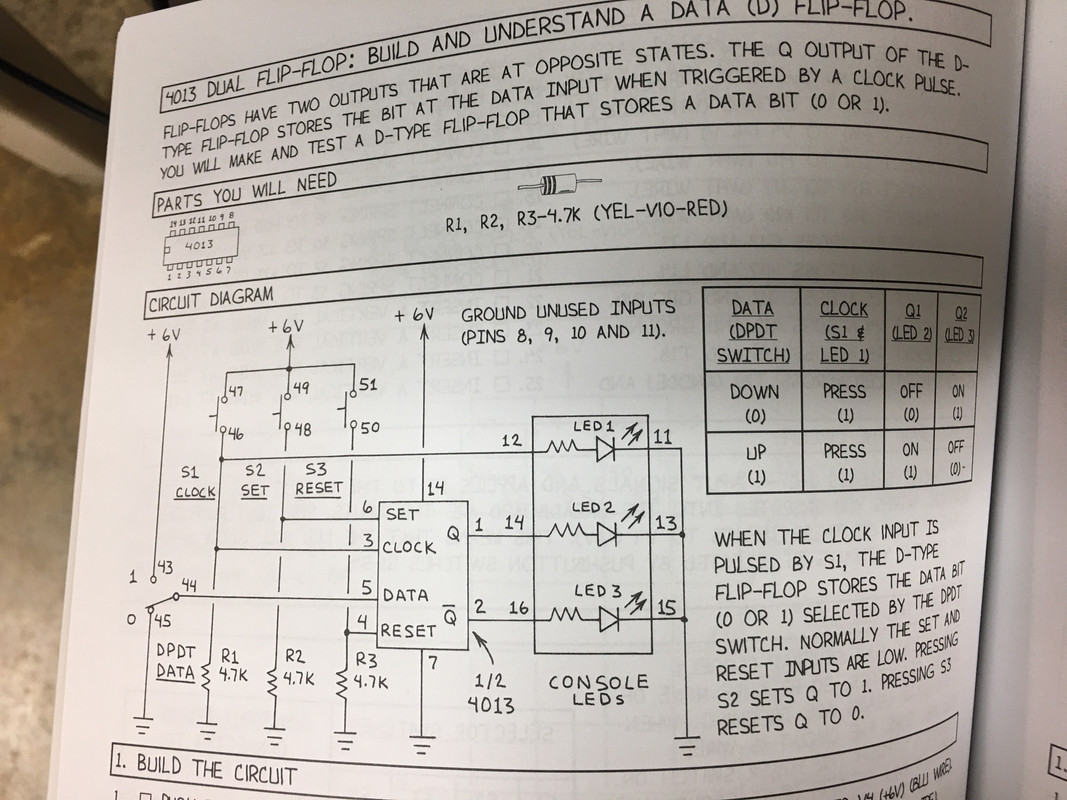
Mims presents this explanation of a 4013 D-type flip flop:

image

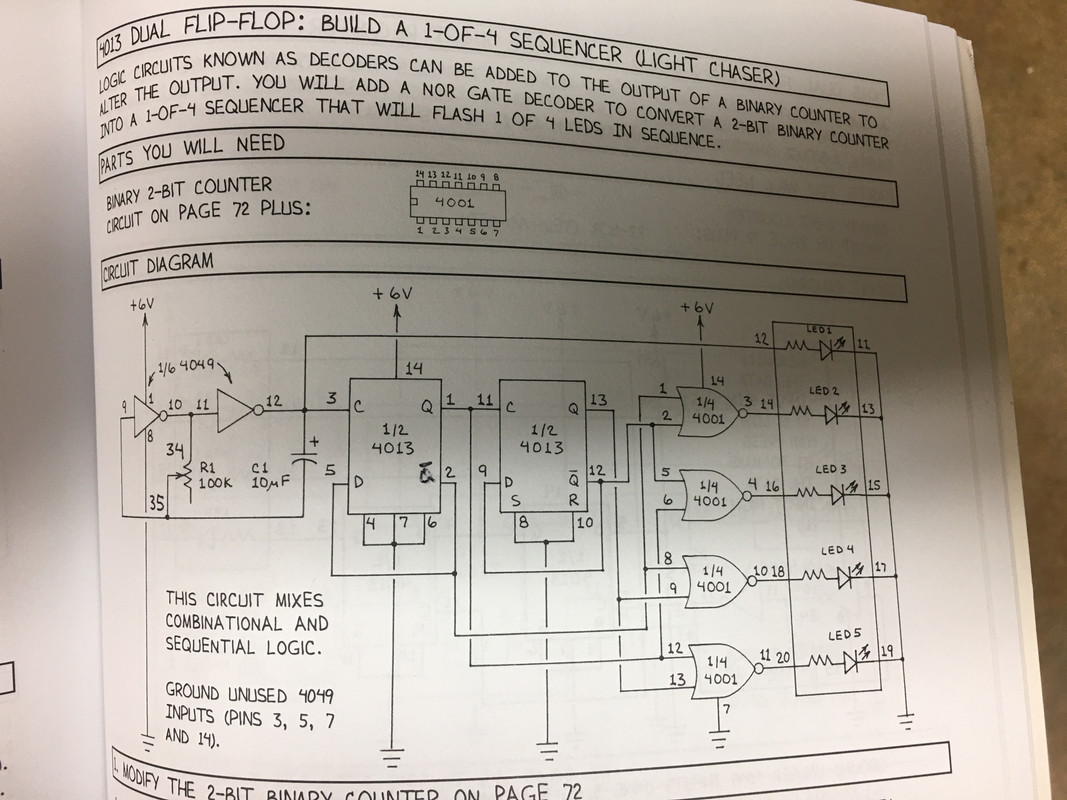
which, as I understand it, on the rising edge of a clock pulse Q1 gets set when D is set.  (By the way, why does he use Q1 and Q2 in the truth table and Q and ~Q (I don't know how to write a Q with a line over it) in the schematic??).  He presents a basic flip flop circuit to demonstrate this :

image

Ok I get when you set D in this circuit with the toggle switch manually, Q1 gets set high (1) with the rising clock pulse!


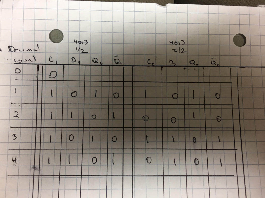
Now the circuit I am working on:

image

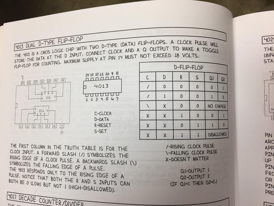
The circuit works as it should, lighting up LED's 1,2,3,4 in sequence.  Ok.  However, when I put a logic probe on pin 5 of the 4013 (D1) with the rising clock pulse starting from 0, D1 is 0 (low) but Q1 is 1 (high). I don't understand why Q1 is set when D1 is low.  Here is the truth table I came up with but it seems to me from the truth table in the image at the top of this post, on rising clock pulse when D1 is 0, ~Q should get set to 1 (high).  I feel like I am missing the sequence of how the outputs get changed but I don't know what...  Help!


image


Thanks!

Robert Opalko


Message was edited by: Robert Opalko


Message was edited by: Robert Opalko
  • Sign in to reply
  • Cancel

Top Replies

  • wolfgangfriedrich
    wolfgangfriedrich over 4 years ago +7 verified
    The short answer is, that the ~Q output (pin2) is connected to the D input (pin5). When the rising edge happens and after the propagation delay of the flipflop the outputs toggle according to the D input…
  • gdstew
    gdstew over 4 years ago in reply to opalko +6 suggested
    Propagation delay, the amount of time an output (Q or ~Q) takes to change after a change in an input (D and clock) for 4000 series ICs is measured in 10s to 100s of nanoseconds depending on the operating…
  • dougw
    dougw over 4 years ago in reply to opalko +6 suggested
    As wolfgangfriedrich points out the FF is operating as it should. When the clock rising edge occurs whatever is at D gets latched to Q. In this case /Q gets latched as the inverse of Q, and it is connected…
Parents
  • opalko
    0 opalko over 4 years ago

    So I think I understand the delay between clock, D, and Q and also that my TT is incomplete and I really need a state diagram showing the changes,... but I am back to my original question: you want 4 LED's to light in a sequence..how do you get from that goal to knowing to use the 4001 and 4013 (and 4049)? Is it done with truth tables?

    • Cancel
    • Vote Up +1 Vote Down
    • Sign in to reply
    • Verify Answer
    • Cancel
Reply
  • opalko
    0 opalko over 4 years ago

    So I think I understand the delay between clock, D, and Q and also that my TT is incomplete and I really need a state diagram showing the changes,... but I am back to my original question: you want 4 LED's to light in a sequence..how do you get from that goal to knowing to use the 4001 and 4013 (and 4049)? Is it done with truth tables?

    • Cancel
    • Vote Up +1 Vote Down
    • Sign in to reply
    • Verify Answer
    • Cancel
Children
  • dougw
    0 dougw over 4 years ago in reply to opalko

    Excellent question.

    There are many ways to solve the requirement.

    People will tend to use what they have used in the past, some would use a microcontroller, some would use a counter and a ROM, some would use an FPGA, some would use daisy-chained one-shots, some would use a Johnson counter, etc.

    But to solve it with just basic knowledge of logic gates without knowing the solution is what engineering is all about.

    One method is to search the internet for similar solutions.

    One method is to look through datasheets until you see something that solves a part of the problem.

    The classic engineering approach is to break the problem down into smaller problems until the solutions are obvious to your level of knowledge.

    If you have some knowledge about state machines, you could start by defining all the states of the system and how successive states relate to previous states. And then work out the logic required to transition from one state to the next.

    Some purists would use a top-down design approach, others would use a bottom-up approach. but most would use a combination.

    For example they might start with something they know that generates a sequence of states, such as a binary counter. If you have a counter that counts to 4, then each state corresponds to a different count on the counter, so to have each counter state turn on a different LED is just a matter of figuring out what logic is needed to recognize each count.

    For example if all bits are off the first LED might illuminate - this is just a NOR gate.

    Incidentally - this is the logic that is inside a Johnson counter - which does the sequential outputs in one chip.

    • Cancel
    • Vote Up +2 Vote Down
    • Sign in to reply
    • Verify Answer
    • Reject Answer
    • Cancel
  • gdstew
    0 gdstew over 4 years ago in reply to opalko

    You might want to look into Karnaugh maps. They are used to simplify generating combinational logic circuits as well as simplifying the circuits themselves.

    • Cancel
    • Vote Up +2 Vote Down
    • Sign in to reply
    • Verify Answer
    • Reject Answer
    • Cancel
element14 Community

element14 is the first online community specifically for engineers. Connect with your peers and get expert answers to your questions.

  • Members
  • Learn
  • Technologies
  • Challenges & Projects
  • Products
  • Store
  • About Us
  • Feedback & Support
  • FAQs
  • Terms of Use
  • Privacy Policy
  • Legal and Copyright Notices
  • Sitemap
  • Cookies

An Avnet Company © 2025 Premier Farnell Limited. All Rights Reserved.

Premier Farnell Ltd, registered in England and Wales (no 00876412), registered office: Farnell House, Forge Lane, Leeds LS12 2NE.

ICP 备案号 10220084.

Follow element14

  • X
  • Facebook
  • linkedin
  • YouTube