element14 Community
element14 Community
    Register Log In
  • Site
  • Search
  • Log In Register
  • Community Hub
    Community Hub
    • What's New on element14
    • Feedback and Support
    • Benefits of Membership
    • Personal Blogs
    • Members Area
    • Achievement Levels
  • Learn
    Learn
    • Ask an Expert
    • eBooks
    • element14 presents
    • Learning Center
    • Tech Spotlight
    • STEM Academy
    • Webinars, Training and Events
    • Learning Groups
  • Technologies
    Technologies
    • 3D Printing
    • FPGA
    • Industrial Automation
    • Internet of Things
    • Power & Energy
    • Sensors
    • Technology Groups
  • Challenges & Projects
    Challenges & Projects
    • Design Challenges
    • element14 presents Projects
    • Project14
    • Arduino Projects
    • Raspberry Pi Projects
    • Project Groups
  • Products
    Products
    • Arduino
    • Avnet & Tria Boards Community
    • Dev Tools
    • Manufacturers
    • Multicomp Pro
    • Product Groups
    • Raspberry Pi
    • RoadTests & Reviews
  • About Us
  • Store
    Store
    • Visit Your Store
    • Choose another store...
      • Europe
      •  Austria (German)
      •  Belgium (Dutch, French)
      •  Bulgaria (Bulgarian)
      •  Czech Republic (Czech)
      •  Denmark (Danish)
      •  Estonia (Estonian)
      •  Finland (Finnish)
      •  France (French)
      •  Germany (German)
      •  Hungary (Hungarian)
      •  Ireland
      •  Israel
      •  Italy (Italian)
      •  Latvia (Latvian)
      •  
      •  Lithuania (Lithuanian)
      •  Netherlands (Dutch)
      •  Norway (Norwegian)
      •  Poland (Polish)
      •  Portugal (Portuguese)
      •  Romania (Romanian)
      •  Russia (Russian)
      •  Slovakia (Slovak)
      •  Slovenia (Slovenian)
      •  Spain (Spanish)
      •  Sweden (Swedish)
      •  Switzerland(German, French)
      •  Turkey (Turkish)
      •  United Kingdom
      • Asia Pacific
      •  Australia
      •  China
      •  Hong Kong
      •  India
      •  Korea (Korean)
      •  Malaysia
      •  New Zealand
      •  Philippines
      •  Singapore
      •  Taiwan
      •  Thailand (Thai)
      • Americas
      •  Brazil (Portuguese)
      •  Canada
      •  Mexico (Spanish)
      •  United States
      Can't find the country/region you're looking for? Visit our export site or find a local distributor.
  • Translate
  • Profile
  • Settings
Experts, Learning and Guidance
  • Technologies
  • More
Experts, Learning and Guidance
Ask an Expert Forum Flipping out on flip-flop basics
  • Blog
  • Forum
  • Documents
  • Leaderboard
  • Files
  • Members
  • Mentions
  • Sub-Groups
  • Tags
  • More
  • Cancel
  • New
Join Experts, Learning and Guidance to participate - click to join for free!
Actions
  • Share
  • More
  • Cancel
Forum Thread Details
  • State Verified Answer
  • Replies 20 replies
  • Answers 11 answers
  • Subscribers 296 subscribers
  • Views 6243 views
  • Users 0 members are here
  • flipflop
Related
See a helpful answer?

Be sure to click 'more' and select 'suggest as answer'!

If you're the thread creator, be sure to click 'more' then 'Verify as Answer'!

Flipping out on flip-flop basics

opalko
opalko over 4 years ago

Hey folks, I am working my way through Forrest Mims' Digital Logic Projects Workbook 2 and stumbling on understanding basic D-type flip-flop operations.  I hope someone can help me understand where I am getting lost.


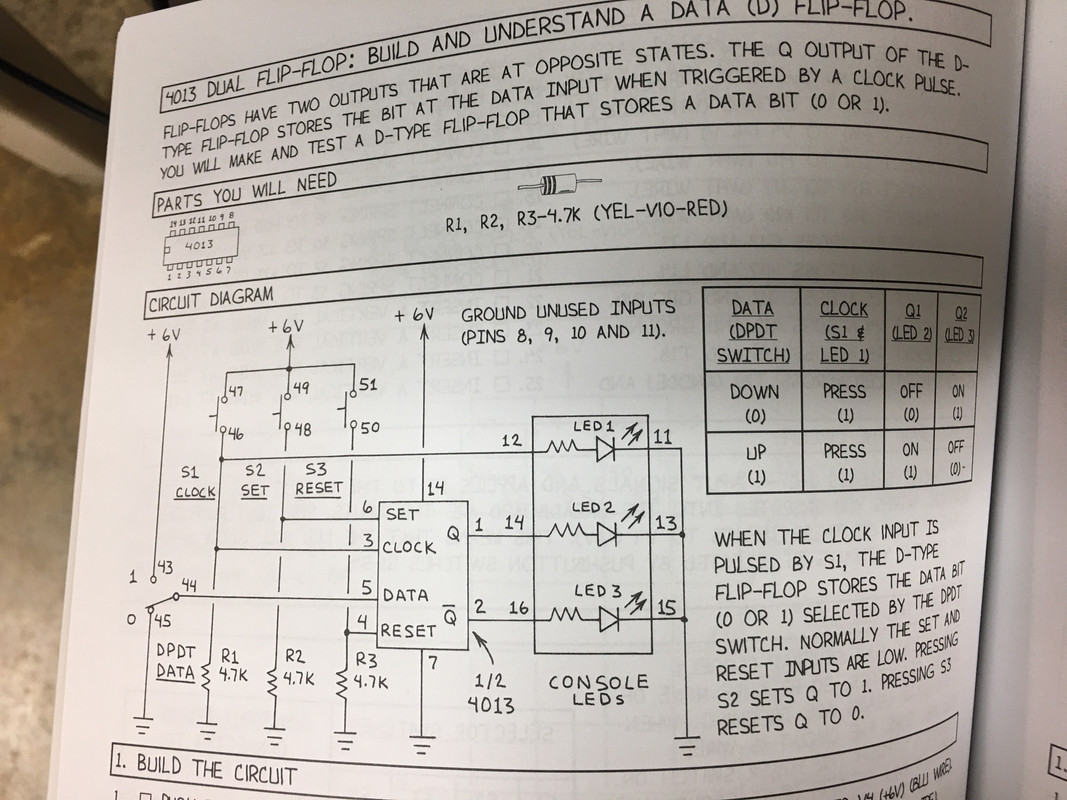
Mims presents this explanation of a 4013 D-type flip flop:

image

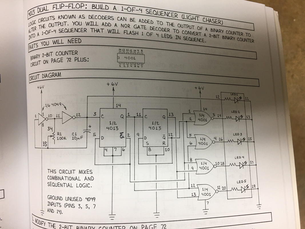
which, as I understand it, on the rising edge of a clock pulse Q1 gets set when D is set.  (By the way, why does he use Q1 and Q2 in the truth table and Q and ~Q (I don't know how to write a Q with a line over it) in the schematic??).  He presents a basic flip flop circuit to demonstrate this :

image

Ok I get when you set D in this circuit with the toggle switch manually, Q1 gets set high (1) with the rising clock pulse!


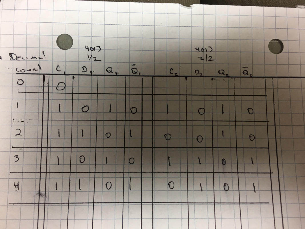
Now the circuit I am working on:

image

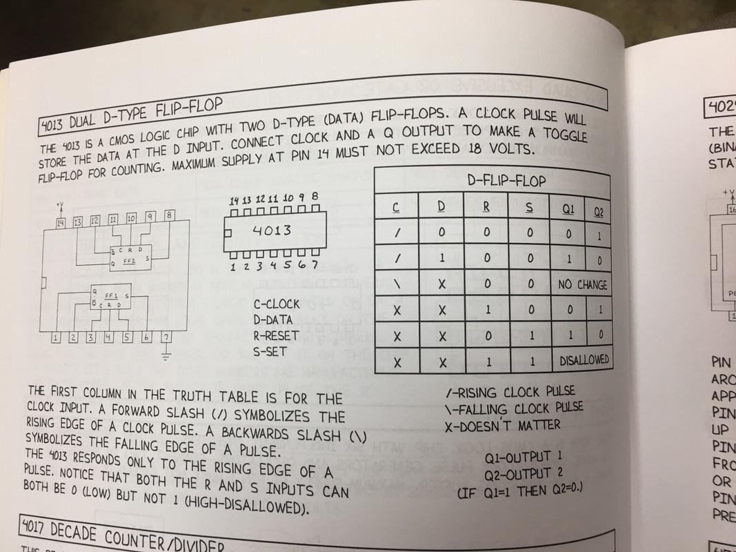
The circuit works as it should, lighting up LED's 1,2,3,4 in sequence.  Ok.  However, when I put a logic probe on pin 5 of the 4013 (D1) with the rising clock pulse starting from 0, D1 is 0 (low) but Q1 is 1 (high). I don't understand why Q1 is set when D1 is low.  Here is the truth table I came up with but it seems to me from the truth table in the image at the top of this post, on rising clock pulse when D1 is 0, ~Q should get set to 1 (high).  I feel like I am missing the sequence of how the outputs get changed but I don't know what...  Help!


image


Thanks!

Robert Opalko


Message was edited by: Robert Opalko


Message was edited by: Robert Opalko
  • Sign in to reply
  • Cancel

Top Replies

  • wolfgangfriedrich
    wolfgangfriedrich over 4 years ago +7 verified
    The short answer is, that the ~Q output (pin2) is connected to the D input (pin5). When the rising edge happens and after the propagation delay of the flipflop the outputs toggle according to the D input…
  • gdstew
    gdstew over 4 years ago in reply to opalko +6 suggested
    Propagation delay, the amount of time an output (Q or ~Q) takes to change after a change in an input (D and clock) for 4000 series ICs is measured in 10s to 100s of nanoseconds depending on the operating…
  • dougw
    dougw over 4 years ago in reply to opalko +6 suggested
    As wolfgangfriedrich points out the FF is operating as it should. When the clock rising edge occurs whatever is at D gets latched to Q. In this case /Q gets latched as the inverse of Q, and it is connected…
Parents
  • opalko
    0 opalko over 4 years ago

    So I think I understand the delay between clock, D, and Q and also that my TT is incomplete and I really need a state diagram showing the changes,... but I am back to my original question: you want 4 LED's to light in a sequence..how do you get from that goal to knowing to use the 4001 and 4013 (and 4049)? Is it done with truth tables?

    • Cancel
    • Vote Up +1 Vote Down
    • Sign in to reply
    • Verify Answer
    • Cancel
  • gdstew
    0 gdstew over 4 years ago in reply to opalko

    You might want to look into Karnaugh maps. They are used to simplify generating combinational logic circuits as well as simplifying the circuits themselves.

    • Cancel
    • Vote Up +2 Vote Down
    • Sign in to reply
    • Verify Answer
    • Reject Answer
    • Cancel
Reply
  • gdstew
    0 gdstew over 4 years ago in reply to opalko

    You might want to look into Karnaugh maps. They are used to simplify generating combinational logic circuits as well as simplifying the circuits themselves.

    • Cancel
    • Vote Up +2 Vote Down
    • Sign in to reply
    • Verify Answer
    • Reject Answer
    • Cancel
Children
No Data
element14 Community

element14 is the first online community specifically for engineers. Connect with your peers and get expert answers to your questions.

  • Members
  • Learn
  • Technologies
  • Challenges & Projects
  • Products
  • Store
  • About Us
  • Feedback & Support
  • FAQs
  • Terms of Use
  • Privacy Policy
  • Legal and Copyright Notices
  • Sitemap
  • Cookies

An Avnet Company © 2025 Premier Farnell Limited. All Rights Reserved.

Premier Farnell Ltd, registered in England and Wales (no 00876412), registered office: Farnell House, Forge Lane, Leeds LS12 2NE.

ICP 备案号 10220084.

Follow element14

  • X
  • Facebook
  • linkedin
  • YouTube