element14 Community
element14 Community
    Register Log In
  • Site
  • Search
  • Log In Register
  • Community Hub
    Community Hub
    • What's New on element14
    • Feedback and Support
    • Benefits of Membership
    • Personal Blogs
    • Members Area
    • Achievement Levels
  • Learn
    Learn
    • Ask an Expert
    • eBooks
    • element14 presents
    • Learning Center
    • Tech Spotlight
    • STEM Academy
    • Webinars, Training and Events
    • Learning Groups
  • Technologies
    Technologies
    • 3D Printing
    • FPGA
    • Industrial Automation
    • Internet of Things
    • Power & Energy
    • Sensors
    • Technology Groups
  • Challenges & Projects
    Challenges & Projects
    • Design Challenges
    • element14 presents Projects
    • Project14
    • Arduino Projects
    • Raspberry Pi Projects
    • Project Groups
  • Products
    Products
    • Arduino
    • Avnet & Tria Boards Community
    • Dev Tools
    • Manufacturers
    • Multicomp Pro
    • Product Groups
    • Raspberry Pi
    • RoadTests & Reviews
  • About Us
  • Store
    Store
    • Visit Your Store
    • Choose another store...
      • Europe
      •  Austria (German)
      •  Belgium (Dutch, French)
      •  Bulgaria (Bulgarian)
      •  Czech Republic (Czech)
      •  Denmark (Danish)
      •  Estonia (Estonian)
      •  Finland (Finnish)
      •  France (French)
      •  Germany (German)
      •  Hungary (Hungarian)
      •  Ireland
      •  Israel
      •  Italy (Italian)
      •  Latvia (Latvian)
      •  
      •  Lithuania (Lithuanian)
      •  Netherlands (Dutch)
      •  Norway (Norwegian)
      •  Poland (Polish)
      •  Portugal (Portuguese)
      •  Romania (Romanian)
      •  Russia (Russian)
      •  Slovakia (Slovak)
      •  Slovenia (Slovenian)
      •  Spain (Spanish)
      •  Sweden (Swedish)
      •  Switzerland(German, French)
      •  Turkey (Turkish)
      •  United Kingdom
      • Asia Pacific
      •  Australia
      •  China
      •  Hong Kong
      •  India
      • Japan
      •  Korea (Korean)
      •  Malaysia
      •  New Zealand
      •  Philippines
      •  Singapore
      •  Taiwan
      •  Thailand (Thai)
      • Vietnam
      • Americas
      •  Brazil (Portuguese)
      •  Canada
      •  Mexico (Spanish)
      •  United States
      Can't find the country/region you're looking for? Visit our export site or find a local distributor.
  • Translate
  • Profile
  • Settings
Experts, Learning and Guidance
  • Technologies
  • More
Experts, Learning and Guidance
Ask an Expert Forum Op Amps in Flight Sim
  • Blog
  • Forum
  • Documents
  • Leaderboard
  • Files
  • Members
  • Mentions
  • Sub-Groups
  • Tags
  • More
  • Cancel
  • New
Join Experts, Learning and Guidance to participate - click to join for free!
Actions
  • Share
  • More
  • Cancel
Forum Thread Details
  • Replies 13 replies
  • Subscribers 303 subscribers
  • Views 2968 views
  • Users 0 members are here
Related
See a helpful answer?

Be sure to click 'more' and select 'suggest as answer'!

If you're the thread creator, be sure to click 'more' then 'Verify as Answer'!

Op Amps in Flight Sim

EAL727Capt
EAL727Capt over 3 years ago

Good day to all.

Long time lurker and first posting; I truly appreciate your patience.

I have been working on constructing a home cockpit representing a Boeing 727-200 using OEM parts/instruments/indicators/gauges I’ve obtained over the years.

Currently, I’m hard-at-work on interfacing these pieces with X-Plane 11.   I have many, many questions and as a relative newcomer to the world of electronics (which is like learning a new foreign language to me most times) I would appreciate some assistance.

I’m working on a Flight Director Indicator (FDI) and a Horizontal Situation Indicator (HSI) which both provide vertical and horizontal guidance to the pilots.  Luckily, I have the pin out assignments and operation manual for the FDI and am having fun hooking-up wires and seeing the dials slowly turn.  The pitch and roll functions are controlled by synchros and motor-generators via 26VAC/400Hz.  The warning flags are powered by 28VDC.

On the topic of op amps—-

There is a ‘needle’ indicator for the glide slope (which provides a ‘path’ to follow when approaching the runway to land).  This needle indicator is biased from view when the glide slope receiver does not detect a glide slope indication.  When approaching the runway and intercepting the glide slope at a specific altitude, the needle will move slowly move down from its hidden view.  When the needle reaches its centered position, you are on the glide slope and continuously descend to the runway, keeping this needle centered.  
This needle requires very little power, both positive and negative.  Full deflection in either direction (above glide path and below glide path)  is minimal; this indicator is extremely sensitive as it is designed to guide the pilot to the runway in very low visibility conditions—precision is paramount.

Given this, an op amp (based upon the reading and research I’ve done) seems the logical choice for operation.  I have been successful in getting the needle to move from full up to full down by switching the leads for positive and negative power, using extremely low amps from my 28VDC bench power supply.  

From the unit’s manual:

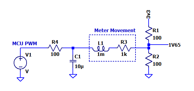
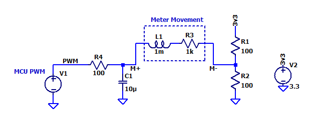
”Meter mechanism sensitivity is 150 +/-20 ua in each direction and is biased from view with 1.5 ma maximum and is in view with 500 ua applied.  Meter resistance is 1000 +/- 30 ohms.”

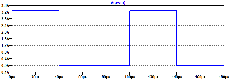
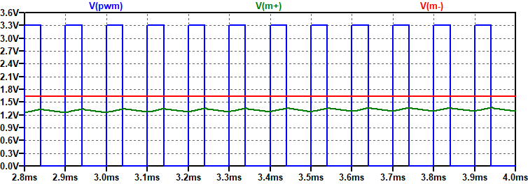
I will be using a Teensy board which provides power of 3.3VDC with PWM.  I’m not concerned with the coding/sketch to drive this instrument as that has already been established.  

How would I apply Ohm’s Law to drive this needle using various values of resistors/diodes or other components, given the tiny amount of amperage (positive and negative) required?  And then the question of which type of op amp to purchase?  I have done some research on the topic of op amps and am still a little unclear to their full capabilities and/or limitations.   I had seen an op amp board available from SparkFun which looked promising but I wanted to first ask as I see many, many friendly, patient and helpful suggestions and advice here.

I certainly appreciate your input.

Jay

Las Vegas, NV

  • Sign in to reply
  • Cancel

Top Replies

  • scottiebabe
    scottiebabe over 3 years ago in reply to EAL727Capt +4
    Hello, you're quite welcome :) The component values were just a rough guess, I choose 100 ohm resistors assuming you wanted to drive upto +- 1.5 mA through the meter movement. You can always use a larger…
  • scottiebabe
    scottiebabe over 3 years ago +2
    Here is a very simple implementation to get you started: Really neat project, btw!
  • shabaz
    shabaz over 3 years ago in reply to scottiebabe +2
    Just wondering, it may be possible to remove the RC filter, although it depends on the movement. On my limited test on a 100 uA movement ( see here: /products/roadtest/rv/roadtest_reviews/509/sensirion_gastemphum…
  • michaelkellett
    michaelkellett over 3 years ago

    The spec you have given doesn't quite make sense to me.

    On the one hand it says the sensitivty is 150uA, then says you should apply 500uA to keep it in view and 1500uA to bias out of view.

    Its 1000R (ohms) so you get 1000uA per volt.

    If you put a 9000 (use 9100R = 9.1k)  resistor in series with the meter then you will get 500uA for about 5V applied.

    (because the total resistance will be 10000R so you'll get V/10000 * 1000,000 uA)

    Then, if you can tell us where the needle is for currents from 0 to 1500uA going up in 100uA steps.

    I think you may not need an op amp at all - just a resistor and capacitor but there isn't quite enough data to be sure.

    MK

    • Cancel
    • Vote Up +1 Vote Down
    • Sign in to reply
    • Cancel
  • Andrew J
    Andrew J over 3 years ago in reply to michaelkellett

    I understood that to be 1500uA maximum.  I.e. apply 501uA to 1500uA to keep it out of view, but no more than that.  That implied to me it functionally operates across a range of 0A to 500uA for the purposes of deflecting the needle.  I think you are interpreting it as functionally operating between 500uA and 1500uA which I can also see now you say it!  That 1.5mA max in the manual would seem to indicate it could breakdown above 1.5mA and would go out of view at a value below 1.5mA, but above 500uA.

    There's also mention of positive and negative power - does it run with a positive and negative power rail?  It may well be the case that it operates in view from -500uA to +500uA (climb or descend).  Jay's experiment with his power supply could support this but it wasn't a nuanced enough experiment to be sure.

    Confusing???  Jay: do you have more info to add from your experiments/investigation?

    Given the use of a 3.3V Teensy, an alternative combination would be a 5600 Ohm resistor: 3.3/(5600 + 1000) = 500uA.  It could then still be characterised in steps of 100uA.  I don't suppose it matters, but it may help depending upon parts to hand.

    It would still be useful to understand the operating range though.

    phoenixcomm just in case you miss this post, I daresay you have good experience to add here.

    • Cancel
    • Vote Up +1 Vote Down
    • Sign in to reply
    • Cancel
  • scottiebabe
    scottiebabe over 3 years ago

    Here is a very simple implementation to get you started:

    image

    Really neat project, btw!

    • Cancel
    • Vote Up +2 Vote Down
    • Sign in to reply
    • Cancel
  • EAL727Capt
    EAL727Capt over 3 years ago

    Thank you all for your replies thus far.

    When I connect the positive power lead to the positive pin on the unit and the negative power lead to the negative pin on the unit, needle deflection is up (indicating flying below the glide path).  A centered needle (flying on the glide path) is obtained at zero volts.

    When I reverse the power leads (e.g., Positive power lead to negative pin, negative power lead to positive pin), needle reflection is down (indicating flying above the glide path).  

    The needle will always indicate where the glide slope beam is, in all cases.


    As little as .2V shoots the needle up (or down, depending on the power lead placement on the unit).

    My assumption here is that very, very, very little voltage is required and the precision of the meter/needle movement is controlled by amps and not volts, hence the op amp question applying either positive or negative amperage for accurate movement.

    As soon as I figure out some way to more accurately control positive and negative amperage, I can then learn the readings with an ammeter and post my findings here.  Again, being new to electronics for testing and practical application with these very old and priceless (to me) instruments, this is currently not in my wheel house!   I fly planes…I don’t usually pull ‘em apart!!!     LOL

    Thank you again.

    Jay

    • Cancel
    • Vote Up 0 Vote Down
    • Sign in to reply
    • Cancel
  • dougw
    dougw over 3 years ago in reply to EAL727Capt

    The circuit supplied by scottiebabe will allow your Teensy PWM output to create a positive and negative voltage and current, where a 50% duty cycle on the PWM would be zero reading or "on glide path indication".

    • Cancel
    • Vote Up 0 Vote Down
    • Sign in to reply
    • Cancel
  • EAL727Capt
    EAL727Capt over 3 years ago in reply to scottiebabe

    Thank you so much for this!

    If I’m understanding this correctly, I only need a Teensy (PWM pin), a 10u capacitor, and 3-100 ohm resistors, with 3 grounds to the Teensy board?  The R1 goes to the 3.3V pin on the Teensy board.

    I’m unclear as to what’s inside the box you’ve entitled ‘meter movement.’

    Thank you for the explanation. 

    Jay

    • Cancel
    • Vote Up 0 Vote Down
    • Sign in to reply
    • Cancel
  • scottiebabe
    scottiebabe over 3 years ago in reply to EAL727Capt

    Hello, you're quite welcome :) The component values were just a rough guess, I choose 100 ohm resistors assuming you wanted to drive upto +- 1.5 mA through the meter movement. You can always use a larger value for C1, as shown below its role is to filter the PWM signal into a somewhat stable voltage. The meter movement will average out the variations in current too.

    The box meter movement is just a schematic equivalent to what I believe to be in the meter. A coil of wire with a resistance of 1kOhms. You would just attach your meter in place of the box, as M+, M-

    image

    For example here is what a 10 kHz, 40% duty cycle pwm value would result in:

    image

    image

    image

    With a 60% duty cycle the meter current is +287 uA

    image

    If it turns out you only need a 100uA of drive current the resistors could be scaled up so you can use a larger duty cycle range on your PWM output.

    • Cancel
    • Vote Up +4 Vote Down
    • Sign in to reply
    • Cancel
  • shabaz
    shabaz over 3 years ago in reply to scottiebabe

    Just wondering, it may be possible to remove the RC filter, although it depends on the movement. On my limited test on a 100 uA movement ( see here: /products/roadtest/rv/roadtest_reviews/509/sensirion_gastemphum ) I didn't see any vibrations at 500 Hz PWM rate, so anything higher than that should naturally be filtered out.

    Another possibility could be to use two outputs, and just have the movement and a single resistor in series, connected across the two outputs. The benefit is that on power-up the movement won't swing in any direction, however the code is more complicated since then two PWMs are required (i.e. set one PWM to zero to move the movement in one direction, and set the other PWM to zero to get movement in the other direction). But the method you describe simplifies the software.

    • Cancel
    • Vote Up +2 Vote Down
    • Sign in to reply
    • Cancel
  • EAL727Capt
    EAL727Capt over 3 years ago in reply to scottiebabe

    I cannot adequately thank you for your interest and replies.  I am grateful.

    Please forgive my complete ignorance on the subject of electronics; as a newcomer, I find it challenging, often overly so, to fully grasp and understand the terminology and nomenclature of components.  What is the ‘1V65’ reference and where is this connected?   The meter, thankfully, only has a positive (red) wire and a negative (black) wire.  I’ve assumed that the MCU is the Teensy board with ‘V1’ being the assigned PWM pin.  

    I'm confident that, in time, I will have a much clearer and better understanding of it all and as it stands presently, I’m a little disoriented in the forest without a flashlight!

    I thank you very kindly for the patience and knowledge.

    Always, 

    Jay

    • Cancel
    • Vote Up +1 Vote Down
    • Sign in to reply
    • Cancel
  • scottiebabe
    scottiebabe over 3 years ago in reply to EAL727Capt

    Hello, all questions are good questions. I think you are doing a great job! The 1V65 reference was to illustrate the nominal output of the voltage divider. In the circuit I suggested there are two building block circuits:

    image

    The voltage divider (https://en.wikipedia.org/wiki/Voltage_divider) creates a voltage reference of half the supply rail (3.3/2 = 1.65V).

    The PWM DAC creates a programmable 0 to 3.3V voltage reference based on duty cycle. Then depending on what duty cycle you output from your MCU, the meter movement can see a voltage of +- 1.65 V between M+ and M-. In this case the current through the meter is largely defined by the meters resistance (1kOhm). If it turns out you don't need the capability to drive 1.5 mA of current through the meter the resistors can be scaled up.

    Feel free to ask more questions Slight smile

    • Cancel
    • Vote Up +2 Vote Down
    • Sign in to reply
    • Cancel
>
element14 Community

element14 is the first online community specifically for engineers. Connect with your peers and get expert answers to your questions.

  • Members
  • Learn
  • Technologies
  • Challenges & Projects
  • Products
  • Store
  • About Us
  • Feedback & Support
  • FAQs
  • Terms of Use
  • Privacy Policy
  • Legal and Copyright Notices
  • Sitemap
  • Cookies

An Avnet Company © 2025 Premier Farnell Limited. All Rights Reserved.

Premier Farnell Ltd, registered in England and Wales (no 00876412), registered office: Farnell House, Forge Lane, Leeds LS12 2NE.

ICP 备案号 10220084.

Follow element14

  • X
  • Facebook
  • linkedin
  • YouTube