element14 Community
element14 Community
    Register Log In
  • Site
  • Search
  • Log In Register
  • Community Hub
    Community Hub
    • What's New on element14
    • Feedback and Support
    • Benefits of Membership
    • Personal Blogs
    • Members Area
    • Achievement Levels
  • Learn
    Learn
    • Ask an Expert
    • eBooks
    • element14 presents
    • Learning Center
    • Tech Spotlight
    • STEM Academy
    • Webinars, Training and Events
    • Learning Groups
  • Technologies
    Technologies
    • 3D Printing
    • FPGA
    • Industrial Automation
    • Internet of Things
    • Power & Energy
    • Sensors
    • Technology Groups
  • Challenges & Projects
    Challenges & Projects
    • Design Challenges
    • element14 presents Projects
    • Project14
    • Arduino Projects
    • Raspberry Pi Projects
    • Project Groups
  • Products
    Products
    • Arduino
    • Avnet & Tria Boards Community
    • Dev Tools
    • Manufacturers
    • Multicomp Pro
    • Product Groups
    • Raspberry Pi
    • RoadTests & Reviews
  • About Us
    About the element14 Community
  • Store
    Store
    • Visit Your Store
    • Choose another store...
      • Europe
      •  Austria (German)
      •  Belgium (Dutch, French)
      •  Bulgaria (Bulgarian)
      •  Czech Republic (Czech)
      •  Denmark (Danish)
      •  Estonia (Estonian)
      •  Finland (Finnish)
      •  France (French)
      •  Germany (German)
      •  Hungary (Hungarian)
      •  Ireland
      •  Israel
      •  Italy (Italian)
      •  Latvia (Latvian)
      •  
      •  Lithuania (Lithuanian)
      •  Netherlands (Dutch)
      •  Norway (Norwegian)
      •  Poland (Polish)
      •  Portugal (Portuguese)
      •  Romania (Romanian)
      •  Russia (Russian)
      •  Slovakia (Slovak)
      •  Slovenia (Slovenian)
      •  Spain (Spanish)
      •  Sweden (Swedish)
      •  Switzerland(German, French)
      •  Turkey (Turkish)
      •  United Kingdom
      • Asia Pacific
      •  Australia
      •  China
      •  Hong Kong
      •  India
      •  Japan
      •  Korea (Korean)
      •  Malaysia
      •  New Zealand
      •  Philippines
      •  Singapore
      •  Taiwan
      •  Thailand (Thai)
      •  Vietnam
      • Americas
      •  Brazil (Portuguese)
      •  Canada
      •  Mexico (Spanish)
      •  United States
      Can't find the country/region you're looking for? Visit our export site or find a local distributor.
  • Translate
  • Profile
  • Settings
Experts, Learning and Guidance
  • Technologies
  • More
Experts, Learning and Guidance
Ask an Expert Forum Struggling to select the correct Analog Switch
  • Blog
  • Forum
  • Documents
  • Leaderboard
  • Files
  • Members
  • Mentions
  • Sub-Groups
  • Tags
  • More
  • Cancel
  • New
Join Experts, Learning and Guidance to participate - click to join for free!
Actions
  • Share
  • More
  • Cancel
Forum Thread Details
  • State Not Answered
  • Replies 12 replies
  • Subscribers 326 subscribers
  • Views 2089 views
  • Users 0 members are here
  • pt100
  • analog switch
Related
See a helpful answer?

Be sure to click 'more' and select 'suggest as answer'!

If you're the thread creator, be sure to click 'more' then 'Verify as Answer'!

Struggling to select the correct Analog Switch

BigG
BigG over 3 years ago

I wish to create this circuit (not a fully complete design), where I am hijacking a Pt100 sensor for my own readings while still allowing an existing system to read the values correctly. I'm thinking that if I switch fast enough, with the help of smoothing capacitors, I could just about get away with it as there will be a fair bit of sampling and averaging to get a temperature value.

To do this, I decided to use an analog switch as these typically have low on resistance values. What I cannot figure out is whether I need a device like a Vishay DG419LEDY-T1-GE4 which has a signal range of -15V to 15V or I could use a SPDT analog switch with a lower voltage. I think I am correct in thinking that the max voltage of Vin is the max voltage allowed through the COM-NC pin etc.

I just wanted confirmation.
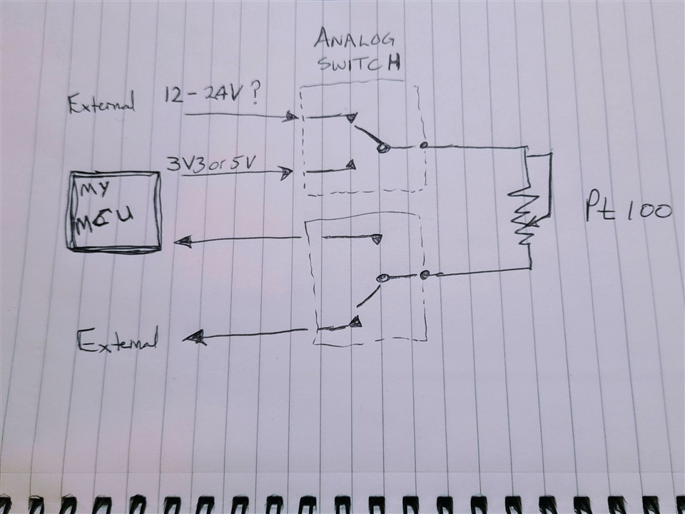
image

Of course, if there is an easier way to do this, I love to hear your views as I have a habit of over complication.

Thanks

Colin

  • Sign in to reply
  • Cancel

Top Replies

  • michaelkellett
    michaelkellett over 3 years ago +3
    What is the existing system ? It may get very upset by the switching, or if are really lucky, you might not need switching at all. I have systems that measure using thermistors where one side if the…
  • BigG
    BigG over 3 years ago in reply to michaelkellett +1
    I was hoping not to switch but could not see how it would work without upsetting the system - I'm also working the principle that more resistance is better than lowering the overall resistance. With the…
  • scottiebabe
    scottiebabe over 3 years ago +1
    Step 1, solve the puzzle Step 2, win the prize Step 3, start probing around :)
  • michaelkellett
    0 michaelkellett over 3 years ago

    What is the existing system ?

    It may get very upset by the switching, or if are really lucky, you might not need switching at all.

    I have systems that measure using thermistors where one side if the the thermistor is grounded and the other connected to a resistor and the micro's adc port.

    When it's time to take the temperature the micro drives the other end of the resitor to 3.3V and measures the voltage across the thermistor. The duty cycle is very low.  A second measuring system could share the thermistor byt detecting when the owner had done a measurement and doing the second measurement in the dead time. So if you know the opwner system well you might not need any high spec switches.

    The switch you suggest has a series resitsance of about 20R and a  typical change of resistance of about 0.1R per degree C. The owner system would have to be recalibrated because this is a large resistance (40R) compared with the Pt100 sensor.  The Pt100 will change by about 0.3R per dgree C so the switch is comparable - this will probably stop the owner system from working at all.

    You can get switches with lower resistance but they won't handle so many volts.

    MK

    • Cancel
    • Vote Up +3 Vote Down
    • Sign in to reply
    • Verify Answer
    • Cancel
  • shabaz
    0 shabaz over 3 years ago

    Hi Colin,

    If there was absolutely no other way (i.e. depends on your use-case/end requirement/connected equipment as Michael says), and you definitely had to read that same PT100, directly at the sensor, then if it were me, I'd probably experiment with a single SPDT reed relay (only needs one, if you've not got any common connections between your system and the existing system), but some systems might check for broken sensor connections, or have other issues with the connection being removed by your microcontroller periodically. Reed relay has current consumption, but still very low overall if (say) the temperature is only being measured (say) once a minute.

    • Cancel
    • Vote Up 0 Vote Down
    • Sign in to reply
    • Verify Answer
    • Cancel
  • BigG
    0 BigG over 3 years ago in reply to michaelkellett

    I was hoping not to switch but could not see how it would work without upsetting the system - I'm also working the principle that more resistance is better than lowering the overall resistance. With the switching scenario I thought that maybe using decoupling or smoothing capacitors could be used to handle millisecond switch time.

    The Pt100 is wired into a control panel, which is locked. The Pt100 is simply used to trigger a warning light to indicate a motor is hot to touch. That's all you get so I want to add in my little monitoring system to capture temperature over time etc. I'm not sure of the voltage used, but as it's out of my control I have assumed for now that it is 12V as the distance between pt100 and control panel is +10metres or so - my wireless device will be much closer to the pt100 sensor. On the control panel you can recalibrate by changing the temperature threshold value to trigger the warning light. I have no other way to accessing the measuring point so need to use same sensor.

    As you have already highlighted a different switch would be better as it has lower resistance values.

    • Cancel
    • Vote Up +1 Vote Down
    • Sign in to reply
    • Verify Answer
    • Cancel
  • BigG
    0 BigG over 3 years ago in reply to shabaz

    Yes needs to be the same Pt100 as cannot insert another sensor in same location. Yes, you are right a single SPDT is probably all I need. Thanks Shabaz for the suggestion to use a reed relay. I will do some research.

    • Cancel
    • Vote Up 0 Vote Down
    • Sign in to reply
    • Verify Answer
    • Cancel
  • BigG
    0 BigG over 3 years ago in reply to michaelkellett

    I would be curious, however, to learn what a non switching "piggy-pack" circuit would look like if the source voltage from the control panel is much higher than my mcu can handle etc.

    Just wanted to add that the reason I like analog switches is the really fast switching time, so you have no dead time. Then I'm assuming my ADC on my MCU can measure a value in milliseconds, I can take a reading, switch back to allow the control panel to do its thing and with help of capacitors not worry too much about the voltage ripple, and then I repeat a second later to collect a decent sample (thinking 5 readings would do it) and then can wait say 30 seconds etc.

    • Cancel
    • Vote Up 0 Vote Down
    • Sign in to reply
    • Verify Answer
    • Cancel
  • Gough Lui
    0 Gough Lui over 3 years ago

    I wouldn't want to break any circuit the existing Pt100 is in, purely because its resistance is so low compared to the actual resistance that would be introduced by your switching elements. That would have a significant impact on the measured temperature by both systems. With a nominal resistance of 100-ohms at 25C, it really won't be happy if you added another 20-ohm (typ at 10mA) for that particular switch for example in the illustrated two-wire connection method.

    For slow-speed switching, perhaps you can get away with a nice gold-plated signal relay depending on the current. That would have much lower contact resistance and thus influence on temperature.

    I would still suggest reverse engineering the current circuit more. Many Pt100-based devices use three-wire or four-wire connections to negate lead resistance for higher accuracy. In the case of four-wire, you could conceivably use higher resistance switches as long as it's being compensated for by the four-wire connection (but watch the limits of compensation by the circuit). If it's three-wire, then likely it will be running a common ground side, so switching one-side and having compensation on that side is a possibility too.

    Instead, if you are able to reverse-engineer it further, then that would be even better. At a guess, most Pt100 RTDs are likely to be driven like a DMM would, with a constant current through its drive pair. A voltage is read back through a sense pair (depending on how it is configured, in two-wire, they are the same; in three-wire, they are separated on one side and commoned on the other; in four-wire, they are all independent). If you can know what this constant current is, then the Pt100 will have a voltage on its sense connections that will tell you the temperature - from there, I would probably choose a low input offset current op-amp and use it as a voltage buffer into your own system. That would present a very high impedance (thus affecting the current circuit very little) and avoid any loading effects. You will have to know what the measurement circuit's voltage is to avoid burning out an opamp, but it's likely to be small because they're not looking for a high current through the RTD, as its self heating would affect the result.

    - Gough

    • Cancel
    • Vote Up 0 Vote Down
    • Sign in to reply
    • Verify Answer
    • Cancel
  • scottiebabe
    0 scottiebabe over 3 years ago

    Step 1, solve the puzzle 

    image

    Step 2, win the prize

    Step 3, start probing around :) 

    • Cancel
    • Vote Up +1 Vote Down
    • Sign in to reply
    • Verify Answer
    • Cancel
  • BigG
    0 BigG over 3 years ago in reply to Gough Lui

    Yep, as I suspected this is a sneaky design challenge.

    Gough Lui said:
    I would still suggest reverse engineering the current circuit more. Many Pt100-based devices use three-wire or four-wire connections to negate lead resistance for higher accuracy. In the case of four-wire, you could conceivably use higher resistance switches as long as it's being compensated for by the four-wire connection (but watch the limits of compensation by the circuit). If it's three-wire, then likely it will be running a common ground side, so switching one-side and having compensation on that side is a possibility too.

    Yes it would be handy if they do that. I'm guessing that I will only find that out once I've messed with things / messed things up.

    The recommended constant current is 1mA so I'm assuming that's what they're using or it's very close to that value.

    I was thinking along similar lines regarding op amp, but as I do not know whether they are  working off a max of 24V or if it's 12V, or somewhere in between.

    • Cancel
    • Vote Up 0 Vote Down
    • Sign in to reply
    • Verify Answer
    • Cancel
  • BigG
    0 BigG over 3 years ago in reply to Gough Lui
    Gough Lui said:
    I would probably choose a low input offset current op-amp and use it as a voltage buffer into your own system. That would present a very high impedance (thus affecting the current circuit very little) and avoid any loading effects.

    I cannot quite see how this works. If possible, could you sketch it - I like pictures Grin

    • Cancel
    • Vote Up 0 Vote Down
    • Sign in to reply
    • Verify Answer
    • Cancel
  • colporteur
    0 colporteur over 3 years ago

    I wish I could contribute BG since you have been helpful to me in the past. I'm not even useful as boat anchor in this case

    I'm curious with the voltage change from low to high, what duration does the device need to stablize in order to obtain a valid reading.

    • Cancel
    • Vote Up 0 Vote Down
    • Sign in to reply
    • Verify Answer
    • Cancel
>
element14 Community

element14 is the first online community specifically for engineers. Connect with your peers and get expert answers to your questions.

  • Members
  • Learn
  • Technologies
  • Challenges & Projects
  • Products
  • Store
  • About Us
  • Feedback & Support
  • FAQs
  • Terms of Use
  • Privacy Policy
  • Legal and Copyright Notices
  • Sitemap
  • Cookies

An Avnet Company © 2026 Premier Farnell Limited. All Rights Reserved.

Premier Farnell Ltd, registered in England and Wales (no 00876412), registered office: Farnell House, Forge Lane, Leeds LS12 2NE.

ICP 备案号 10220084.

Follow element14

  • X
  • Facebook
  • linkedin
  • YouTube