element14 Community
element14 Community
    Register Log In
  • Site
  • Search
  • Log In Register
  • Community Hub
    Community Hub
    • What's New on element14
    • Feedback and Support
    • Benefits of Membership
    • Personal Blogs
    • Members Area
    • Achievement Levels
  • Learn
    Learn
    • Ask an Expert
    • eBooks
    • element14 presents
    • Learning Center
    • Tech Spotlight
    • STEM Academy
    • Webinars, Training and Events
    • Learning Groups
  • Technologies
    Technologies
    • 3D Printing
    • FPGA
    • Industrial Automation
    • Internet of Things
    • Power & Energy
    • Sensors
    • Technology Groups
  • Challenges & Projects
    Challenges & Projects
    • Design Challenges
    • element14 presents Projects
    • Project14
    • Arduino Projects
    • Raspberry Pi Projects
    • Project Groups
  • Products
    Products
    • Arduino
    • Avnet Boards Community
    • Dev Tools
    • Manufacturers
    • Multicomp Pro
    • Product Groups
    • Raspberry Pi
    • RoadTests & Reviews
  • Store
    Store
    • Visit Your Store
    • Choose another store...
      • Europe
      •  Austria (German)
      •  Belgium (Dutch, French)
      •  Bulgaria (Bulgarian)
      •  Czech Republic (Czech)
      •  Denmark (Danish)
      •  Estonia (Estonian)
      •  Finland (Finnish)
      •  France (French)
      •  Germany (German)
      •  Hungary (Hungarian)
      •  Ireland
      •  Israel
      •  Italy (Italian)
      •  Latvia (Latvian)
      •  
      •  Lithuania (Lithuanian)
      •  Netherlands (Dutch)
      •  Norway (Norwegian)
      •  Poland (Polish)
      •  Portugal (Portuguese)
      •  Romania (Romanian)
      •  Russia (Russian)
      •  Slovakia (Slovak)
      •  Slovenia (Slovenian)
      •  Spain (Spanish)
      •  Sweden (Swedish)
      •  Switzerland(German, French)
      •  Turkey (Turkish)
      •  United Kingdom
      • Asia Pacific
      •  Australia
      •  China
      •  Hong Kong
      •  India
      •  Korea (Korean)
      •  Malaysia
      •  New Zealand
      •  Philippines
      •  Singapore
      •  Taiwan
      •  Thailand (Thai)
      • Americas
      •  Brazil (Portuguese)
      •  Canada
      •  Mexico (Spanish)
      •  United States
      Can't find the country/region you're looking for? Visit our export site or find a local distributor.
  • Translate
  • Profile
  • Settings
Experts, Learning and Guidance
  • Technologies
  • More
Experts, Learning and Guidance
Ask an Expert Forum MC1377P video circuit drops to almost 0 when terminated with 75 ohm. Any ideas?
  • Blog
  • Forum
  • Documents
  • Leaderboard
  • Files
  • Members
  • Mentions
  • Sub-Groups
  • Tags
  • More
  • Cancel
  • New
Join Experts, Learning and Guidance to participate - click to join for free!
Actions
  • Share
  • More
  • Cancel
Forum Thread Details
  • Replies 12 replies
  • Subscribers 276 subscribers
  • Views 728 views
  • Users 0 members are here
  • mc1377p
Related
See a helpful answer?

Be sure to click 'more' and select 'suggest as answer'!

If you're the thread creator, be sure to click 'more' then 'Verify as Answer'!

MC1377P video circuit drops to almost 0 when terminated with 75 ohm. Any ideas?

baldengineer
baldengineer over 3 years ago

A project I've been working on for several months, or years depending on how you count, is build a Mini Apple IIe. (Originally it was a portable, now its just a mini.) The key to the project is the MEGA-II ASIC from the Apple IIgs. It contains all of the support logic found in old Apple II computers. (Approximately 80 7400-series chips!).


Since no one has ever used the MEGA-II in this way, I decided to build a couple of prototype boards to test three key sections: 6502, MEGA-II, and VGC. Turns out, we have the 65c02 and MEGA-II to be seemingly working. It even attempts to boot the Apple IIe ROM. (And then it appears to panic.)


So, I moved our attention to the video board. There are two basic sections on the board: the digital side and the analog side. The digital side consists of the VGC (video graphics controller) ASIC and three 4-bit DACs for RGB. Long story short, the MEGA-II generates the classic Apple II video bitstream, the VGC+DAC section converts it to analog R,G,B.


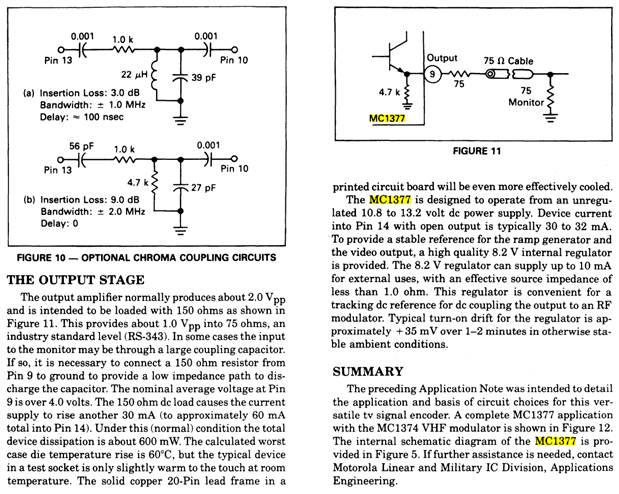
The analog part of the video circuit is based on an MC1377 RGB-to-NTSC encoder. That is the part of the circuit giving me trouble. In this iteration of the project, I just copied the circuit from the Apple IIgs. (My final project won't have composite.) The problem is that when I attach a video receiver or terminate the MC1377's output with 75-ohms, its output drops from 2.6 Vpp to 300 mVpp. A bit too small.


Here's the circuit:

image

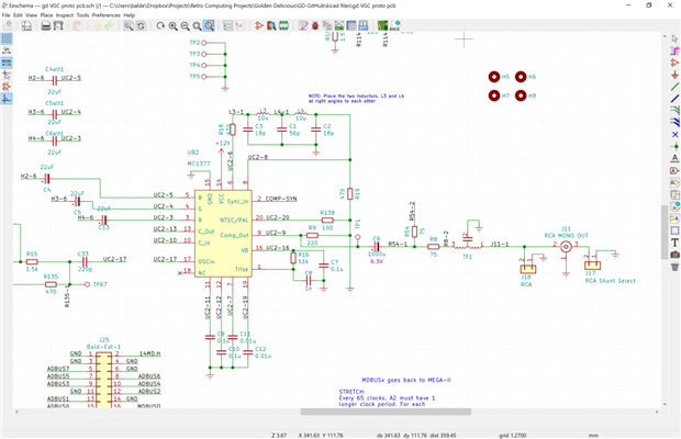
The Full KiCad file is available here.


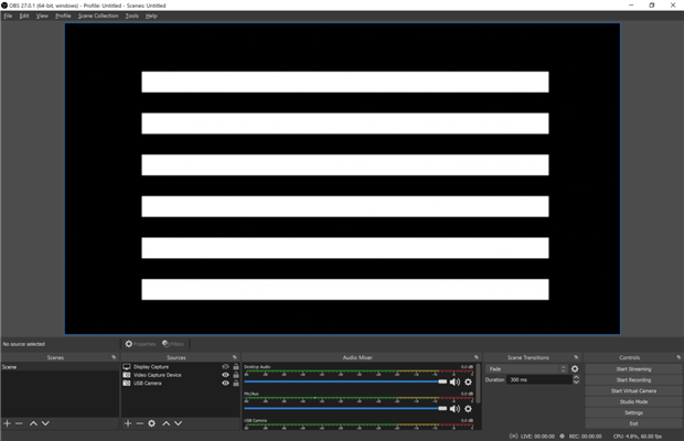
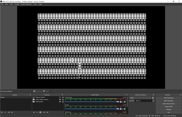
Here's the comparison of output:

image

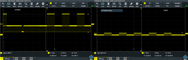
In both cases I am, effectively, probing at J18's signal. On the right, I terminate that node with a 75 ohm resistor. (Same behavior with an actual composite receiver.)


A bunch more waveforms and link to MC1377P datasheet here: https://www.baldengineer.com/mc1377-measurements-on-mini-apple-iie-prototype-video-board.html .


Any ideas why the output is clamping so hard?

  • Sign in to reply
  • Cancel
  • shabaz
    shabaz over 3 years ago

    Hi James,


    Sounds like a great project! Looking forward to seeing it in a video or writeup.

    I've not seen the Apple schematic, but it seems more complicated than the datasheet one. The datasheet suggests that the load should be 150 ohm, is the R54_2 connection going to ground or something?

    I couldn't see where that net went.

    What is TF1, is it to reduce noise? It may be worth shorting it out as an experiment, just in case the inductance or capacitance is too high.

    Also, I guess the MC1377 is from a reputable source, otherwise it may be already faulty perhaps : (

    image

    • Cancel
    • Vote Up 0 Vote Down
    • Sign in to reply
    • Cancel
  • jc2048
    jc2048 over 3 years ago

    shabaz just beat me to it. These were my thoughts for what they're worth:


    Is R54-2 unconnected?


    When you terminate and the signal at J18 collapses, what does the chip output do? Is it still pushing out 2V pk/pk or does it collapse in proportion?


    The datasheet suggests a lower value for the load resistor R9 when using a coupling capacitor. Not sure it would make as much difference as you're seeing, but might be worth looking at.

    • Cancel
    • Vote Up 0 Vote Down
    • Sign in to reply
    • Cancel
  • baldengineer
    baldengineer over 3 years ago
    Found It!


    There is a 220 ohm resistor on pin 9. geekboy1011 pointed out that the datasheet says when used with a 150 ohm resistor, the MC1377 should be drawing 60 milliamps. Initially, I misread the passage and dismissed it because the current draw was around 40 milliamps.


    Realizing we should be drawing 60 milliamps, I rechecked that resistor. A bad solder joint had it floating. After touching up the solder, the MC1377 now draws 60.0 milliamps (strange, right?). Most importantly, the video signal looks correct loaded, AND unloaded.


    image

    bar pattern on cold boot


    image

    bar pattern on warm boot/reset


    Based on my previous logic analyzer traces, I'm pretty sure the ROM is getting stuck very early in the boot process. It finds its way into the interrupt service vector, despite having IRQ de-asserted with a pull-up. Makes me think the code gets lost at some point. (However, the first 10 or instructions look right when compared to the IIe's ROM file.)


    But now that video outputs something and appears to output valid characters, I can get back to the boot process.

    • Cancel
    • Vote Up 0 Vote Down
    • Sign in to reply
    • Cancel
  • baldengineer
    baldengineer over 3 years ago in reply to shabaz

    Thanks for the taking the time to give it a look over and suggesting a few ideas shabaz. Look below for a reply, we found the problem. R9 was not connected.


    The 150 vs 220 doesn't seem to matter. Not sure why the Apple design went with the 220. I'm pretty sure there is a 150 somewhere else in the design.
    TF1 does appear to be for noise/EMI. On a functioning two IIgs, I removed and shorted the path. It had no effect. Though, I was thinking for a while it did some kind of isolation.
    • Cancel
    • Vote Up 0 Vote Down
    • Sign in to reply
    • Cancel
  • baldengineer
    baldengineer over 3 years ago in reply to jc2048

    Thanks Jon for looking it over. Yeah R54-2 is unconnected. It goes to a header pin in my design and it goes to the RGB connector in Apple's design. I think its just a copy of the composite signal for external monitors. I tried terminating that one too. If both R54-2 and J17 went to 75 ohms, the output was in the 10s of millivolts.


    For the record, when terminated, the output of the chip dropped as well. After futzing with the passives after that point, it definitely looked like the amplifier was clamping for some reason.  (see below for the solution, R9 was unnconnected.)

    • Cancel
    • Vote Up 0 Vote Down
    • Sign in to reply
    • Cancel
  • baldengineer
    baldengineer over 3 years ago

    Here's the hardware that generated that screen.


    image


    There are three boards. The top left with the huge 84-pin PLCC is the MEGA-II from an Apple IIgs. It contains all Memory, IOU, Clocks, and GLU circuits from an Apple IIe. It has four 4167 DRAMs on it. To the right is a board for the Video Controller Chip (VGC) from an Apple IIgs. As I described above, half the chip is digital, the other half generates the analog video signals. Under the MEGA-II board is a (modern) 65c02 based board with an EPROM. Currently, the EPROM is programmed with the Apple IIe Unenhanced CD and EF ROMs.


    The Apple IIe used two ROM chips while the IIc used a single ROM chip. The MEGA-II is somewhat of a hybrid of IIe and IIc logic. So I may end up with the IIc ROM.


    Seeing a screen of seemingly garbage characters has made my day. There's a lot of things working (and probably a lot that isn't.)


    I've been streaming this entire project on Twitch. Last night was the 24th stream related to the project. On average, they last 3 hours.


    P.S. Shout-out to OSHPark. They donated the prototype boards. Because I broke out almost every pin and knew I'd have a ton of flying wires, I went four-layer. One inner layer is (mostly) 5V, the other is GND. Copper pours on top and bottom are also GND.


    And to answer a common question, a new thing I've been doing is the exposed ground planes around the edges. Makes it much easier to attach scope probes.

    • Cancel
    • Vote Up 0 Vote Down
    • Sign in to reply
    • Cancel
  • wolfgangfriedrich
    wolfgangfriedrich over 3 years ago in reply to baldengineer

    baldengineer

    Unrelated question: What video capture hardware are you using to display the composite video from your awesome project in OBS?

    Thanks,

    - W.

    • Cancel
    • Vote Up 0 Vote Down
    • Sign in to reply
    • Cancel
  • wolfgangfriedrich
    wolfgangfriedrich over 3 years ago

    here: https://www.baldengineer.com/mc1377-measurements-on-mini-apple-iie-prototype-video-board.html .

    I had a good laugh at the category tag of this article on your website. So meta and I have to buy some, they are yum.

    • Cancel
    • Vote Up 0 Vote Down
    • Sign in to reply
    • Cancel
  • baldengineer
    baldengineer over 3 years ago in reply to wolfgangfriedrich

    Currently, I'm using a RetroTink 2X Pro to capture the composite signal. That goes into a cheap ($20) HDMI-to-USB adapter.


    The RetroTink does have a little bit of trouble doing color with the IIgs video signal. I haven't tested the color modes on my board yet. But I copied the IIgs video circuit, so I suspect I'll have the same issue.


    Interestingly, the IIgs and the IIe generate the composite signal very different from each other. The II/II+/IIe all do the funky Woz stuff, which the RetroTnk handles fine. From what I can tell, the IIgs circuit is way more "legal" NTSC. But the RetroTnk can't lock on to the color burst for some reason.

    • Cancel
    • Vote Up 0 Vote Down
    • Sign in to reply
    • Cancel
  • baldengineer
    baldengineer over 3 years ago in reply to wolfgangfriedrich

    Golden Delicious was my original "code name" for the project. I thought of it because I was taking chips out of the IIgs. so: Golden deliciouS. I thought Apple IIgd would be clever.


    Back then, I also planned to make a portable/handheld computer. But, I recently decided to ditch the portable aspect. Instead I want to make something similar to the "The C64 Mini." The final PCB will go into a scaled-down version of a IIe case.


    Also, thanks to the most recent KansasFest, I've heard the original name for the IIgs was "Cortland." It's a type of apple that is cross bred between the McIntosh and the Ben Davis. McIntosh should be an obvious connection. However the Ben Davis, back in the day, was known as a cash-crop for apple growers. So the name "Cortland" is absolutely perfect for the IIgs.


    Cortland was a cross between the new desirable and well-established, just like the IIgs.

    • Cancel
    • Vote Up 0 Vote Down
    • Sign in to reply
    • Cancel
>
element14 Community

element14 is the first online community specifically for engineers. Connect with your peers and get expert answers to your questions.

  • Members
  • Learn
  • Technologies
  • Challenges & Projects
  • Products
  • Store
  • About Us
  • Feedback & Support
  • FAQs
  • Terms of Use
  • Privacy Policy
  • Legal and Copyright Notices
  • Sitemap
  • Cookies

An Avnet Company © 2025 Premier Farnell Limited. All Rights Reserved.

Premier Farnell Ltd, registered in England and Wales (no 00876412), registered office: Farnell House, Forge Lane, Leeds LS12 2NE.

ICP 备案号 10220084.

Follow element14

  • X
  • Facebook
  • linkedin
  • YouTube