element14 Community
element14 Community
    Register Log In
  • Site
  • Search
  • Log In Register
  • Community Hub
    Community Hub
    • What's New on element14
    • Feedback and Support
    • Benefits of Membership
    • Personal Blogs
    • Members Area
    • Achievement Levels
  • Learn
    Learn
    • Ask an Expert
    • eBooks
    • element14 presents
    • Learning Center
    • Tech Spotlight
    • STEM Academy
    • Webinars, Training and Events
    • Learning Groups
  • Technologies
    Technologies
    • 3D Printing
    • FPGA
    • Industrial Automation
    • Internet of Things
    • Power & Energy
    • Sensors
    • Technology Groups
  • Challenges & Projects
    Challenges & Projects
    • Design Challenges
    • element14 presents Projects
    • Project14
    • Arduino Projects
    • Raspberry Pi Projects
    • Project Groups
  • Products
    Products
    • Arduino
    • Avnet & Tria Boards Community
    • Dev Tools
    • Manufacturers
    • Multicomp Pro
    • Product Groups
    • Raspberry Pi
    • RoadTests & Reviews
  • About Us
  • Store
    Store
    • Visit Your Store
    • Choose another store...
      • Europe
      •  Austria (German)
      •  Belgium (Dutch, French)
      •  Bulgaria (Bulgarian)
      •  Czech Republic (Czech)
      •  Denmark (Danish)
      •  Estonia (Estonian)
      •  Finland (Finnish)
      •  France (French)
      •  Germany (German)
      •  Hungary (Hungarian)
      •  Ireland
      •  Israel
      •  Italy (Italian)
      •  Latvia (Latvian)
      •  
      •  Lithuania (Lithuanian)
      •  Netherlands (Dutch)
      •  Norway (Norwegian)
      •  Poland (Polish)
      •  Portugal (Portuguese)
      •  Romania (Romanian)
      •  Russia (Russian)
      •  Slovakia (Slovak)
      •  Slovenia (Slovenian)
      •  Spain (Spanish)
      •  Sweden (Swedish)
      •  Switzerland(German, French)
      •  Turkey (Turkish)
      •  United Kingdom
      • Asia Pacific
      •  Australia
      •  China
      •  Hong Kong
      •  India
      •  Korea (Korean)
      •  Malaysia
      •  New Zealand
      •  Philippines
      •  Singapore
      •  Taiwan
      •  Thailand (Thai)
      • Americas
      •  Brazil (Portuguese)
      •  Canada
      •  Mexico (Spanish)
      •  United States
      Can't find the country/region you're looking for? Visit our export site or find a local distributor.
  • Translate
  • Profile
  • Settings
Experts, Learning and Guidance
  • Technologies
  • More
Experts, Learning and Guidance
Ask an Expert Forum Is there a way to automate a reset using a USB to UART bridge if it's connected to a Raspberry Pi
  • Blog
  • Forum
  • Documents
  • Leaderboard
  • Files
  • Members
  • Mentions
  • Sub-Groups
  • Tags
  • More
  • Cancel
  • New
Join Experts, Learning and Guidance to participate - click to join for free!
Actions
  • Share
  • More
  • Cancel
Forum Thread Details
  • State Not Answered
  • Replies 22 replies
  • Subscribers 289 subscribers
  • Views 3126 views
  • Users 0 members are here
  • usb host
Related
See a helpful answer?

Be sure to click 'more' and select 'suggest as answer'!

If you're the thread creator, be sure to click 'more' then 'Verify as Answer'!

Is there a way to automate a reset using a USB to UART bridge if it's connected to a Raspberry Pi

BigG
BigG over 1 year ago

I am trying to design a circuit for a new sensor board which essentially uses UART comms but I want to incorporate the option for USB to allow you to use a USB cable from a Raspberry Pi USB host to the sensor board.

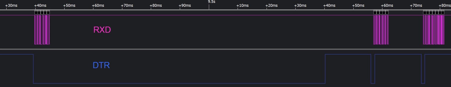
But if I'm using USB I don't have access to the Raspberry Pi's reset pin via the USB cable. This is no problem if the Raspberry Pi powers up, but that is no good if the Raspberry Pi reboots. I would like to have it that if the Raspberry Pi reboots, my sensor board will do so too.

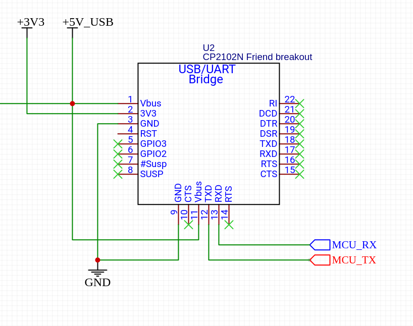
To simplify the design and testing process I am using one of these breakout boards: www.adafruit.com/.../5335

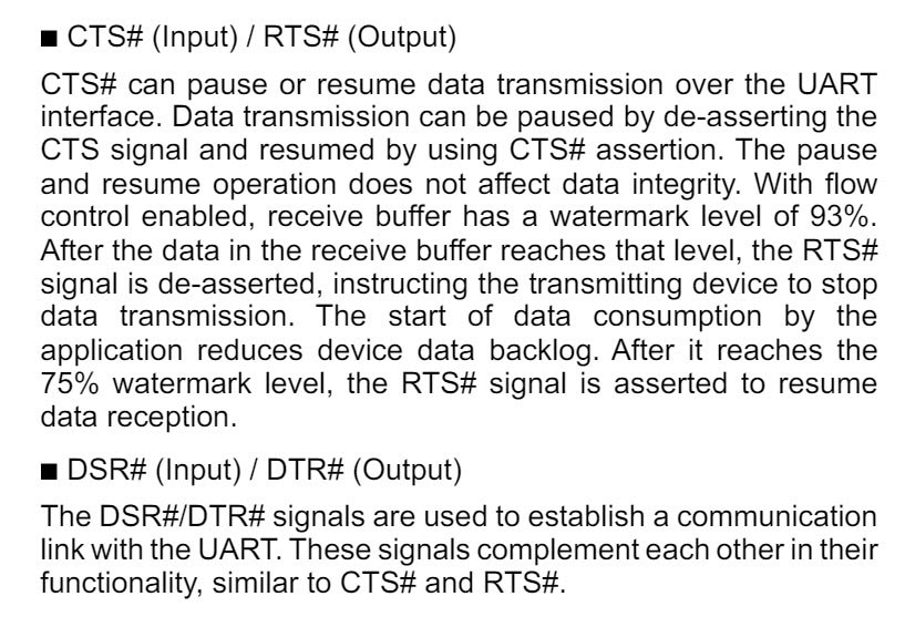
This uses a CP2102N and breaks out DTR, RTS, CTS etc etc. So I have options.

image

But I don't have any ideas... hence the question

  • Sign in to reply
  • Cancel

Top Replies

  • BigG
    BigG over 1 year ago in reply to shabaz +2
    Yes, that's my goal. I'm looking for a magical solution that does not involve using any extra GPIO pins. The idea of using UART break is certainly an interesting one. So, thanks for the circuit... I…
  • shabaz
    shabaz over 1 year ago in reply to BigG +2
    Here's a bit more of a sensible circuit! : ) Exactly same concept, but uses a cheap IC (74HC14), and eliminates awkwardness of the previous circuit, which may load the input, and it was pretty crude…
  • shabaz
    shabaz over 1 year ago +1
    Hi Colin, There's this blog post which I think implements what you're requesting, which is a way for a Pi (or any other host) to control GPIO, so that it can remotely reboot a device if the software…
Parents
  • shabaz
    0 shabaz over 1 year ago

    Hi Colin,

    There's this blog post which I think implements what you're requesting, which is a way for a Pi (or any other host) to control GPIO, so that it can remotely reboot a device if the software on the Pi restarts.  Simple USB Control of GPIO: Automating Device Resets and Bootloader Mode Buttons 

    I didn't try building for Pi however, so am only 80% sure if that will work. Also, that blog is using a different USB-UART chip (but a really good one).

    If you want to stick to the CP2102N, then control of GPIO is discussed here:

    /products/roadtest/rv/roadtest_reviews/155/silicon_labs_usb-to_1

    However, the CP2102N code doesn't support Linux too well (the Linux SDK code looked pretty ancient back when that review was written, maybe it's improved now), so there may be issues with using it with Raspberry Pi.

    Another trick (which doesn't care about host SDK) is to use any generic simple microcontroller on your sensor board, and get it to detect some special UART sequence. It can piggy-back onto the received data UART line, and control the power to your sensor. It doesn't matter if the sensor doesn't like the special sequence, because it will get reset after that.

    Possible candidate for an ultra-cheap simple microcontroller could be the one described here:  Low-Cost Microcontrollers: Using a CH32V003 RISC-V Device! 

    There is UART example code at that link. But you could use any microcontroller of course. 

    • Cancel
    • Vote Up +1 Vote Down
    • Sign in to reply
    • Verify Answer
    • Cancel
  • BigG
    0 BigG over 1 year ago in reply to shabaz

    Thanks Shabaz.

    This is great. It sounds like there is certainly options out there. I will have a read through your blogs and the road test report.

    For background, what triggered my interest in the CP2102N and the possibility for hardware style reset was this schematic for the Adafruit ESP32 Feather V2 board.

    https://learn.adafruit.com/assets/109518

    The schematic shows this sort of arrangement, but I'm still trying to figure out how this works in conjunction with the CP2102N USB to serial converter shown.

    image

    • Cancel
    • Vote Up 0 Vote Down
    • Sign in to reply
    • Verify Answer
    • Cancel
  • shabaz
    0 shabaz over 1 year ago in reply to BigG

    While that works, I think it's dependent on the OS (e.g. might be quite different to control that using say Windows versus Linux or Mac etc) to allow control of those pins. I've never tried it myself, but have seen that on some boards.

    Personally if I really was sure just a single pin of control is needed, then I'd investigate using UART break. since that doesn't require anything special with any OS, and would not require a USB-UART with the extra connections either.

    Something like the below circuit might work (will need tweaking of component values to suit the desired baud rate).

    How it works: Basically, if the RX pin goes low for any long length of time (a normally disallowed thing for UART) then the capacitor slowly charges up, pulling the BJT base low. That then results in the RESET OUT pin going high, asserting reset until the RX pin goes high.

    With normal serial data, the RX pin only goes low for a short amount of time, which isn't enough time to discharge the cap.

    Whenever you wanted to perform a reset, you would deliberately set the baud rate in your host program to a low value, and send a null character (i.e. 0x00). Then you'd change to your normal baud rate.

    The circuit is deliberately low-cost, but could be replaced with something more sophisticated if desired (e.g. logic gates or a microcontroller), but I think the single BJT+two diodes method could be made to work with appropriate component values for the resistors and capacitor.

    image

    • Cancel
    • Vote Up +1 Vote Down
    • Sign in to reply
    • Verify Answer
    • Cancel
  • BigG
    0 BigG over 1 year ago in reply to shabaz

    Yes, that's my goal. I'm looking for a magical solution that does not involve using any extra GPIO pins. The idea of using UART break is certainly an interesting one.

    So, thanks for the circuit... I couldn't quite see how it works but now that I've discovered my new best (electronics software) friend, I can visualise how it works.... this is just simulating UART RX pulsing every 100msec and it shows how RESET OUT alternates from high to low etc. Cooool.

    image

    • Cancel
    • Vote Up +2 Vote Down
    • Sign in to reply
    • Verify Answer
    • Cancel
  • shabaz
    0 shabaz over 1 year ago in reply to BigG

    Here's a bit more of a sensible circuit! : ) 

    Exactly same concept, but uses a cheap IC (74HC14), and eliminates awkwardness of the previous circuit, which may load the input, and it was pretty crude. This one is much cleaner. 74HC14 only costs 33p in single qty, so it should be fine for anything except the most price-sensitive products.

    The 100k resistor and 100nF capacitor set the RC time constant, and it should (I think) work with 300 baud 0x00 character for creating the break sequence, and any sensible baud rate (i.e. 9600 or higher) will easily take the target out of reset.

    Another bonus, there is both negative and positive asserted outputs, so it's more flexible. Plus, there are two spare inverters for any other purpose.

    It is probably worth putting a 100k pull-up on the input of this circuit, just to keep things in a known state if the USB side is disconnected.

    It could be worth assembling this on a breadboard, to see if it works. I'd give it a shot, but am a bit tied up for a few days : (

    EDIT: Also it needs a 100nF decoupling capacitor across the IC.

    image

    • Cancel
    • Vote Up +2 Vote Down
    • Sign in to reply
    • Verify Answer
    • Cancel
  • BigG
    0 BigG over 1 year ago in reply to shabaz

    Thanks Shabaz. Good to see how this circuit design is evolving. Your contribution is much appreciated.

    I just so happened to stumble across the LM66100 from TI, which is a Single-Input, Single-Output (SISO) integrated ideal diode.

    www.ti.com/.../LM66100

    So, as one often does we look for applications, and I thought that maybe we could apply it here where instead of UART TX data break we use DTR. So, wondering if this would work as the input... it's about 40p

    image

    • Cancel
    • Vote Up 0 Vote Down
    • Sign in to reply
    • Verify Answer
    • Cancel
  • BigG
    0 BigG over 1 year ago in reply to BigG

    Doh! If the 74HC14 is an inverter I don't even need to use the LM66100. As you say your circuit has two spare gates, so can we use one for DTR.

    • Cancel
    • Vote Up 0 Vote Down
    • Sign in to reply
    • Verify Answer
    • Cancel
Reply
  • BigG
    0 BigG over 1 year ago in reply to BigG

    Doh! If the 74HC14 is an inverter I don't even need to use the LM66100. As you say your circuit has two spare gates, so can we use one for DTR.

    • Cancel
    • Vote Up 0 Vote Down
    • Sign in to reply
    • Verify Answer
    • Cancel
Children
  • shabaz
    0 shabaz over 1 year ago in reply to BigG

    I wasn't sure what the DTR is needed for (the UART break works without it), but agree, if you need that DTR inversion, you've got the spare capacity for that with the 74HC14.

    Now I think about it, the RXD-line UART break is actually more 'standard' than the Adafruit DTR/RTS circuit. It just happens that the Adafruit option is cheaper when those connections are available and if there is more control of the host software to implement it. Whereas, the 'break' is standard in lots of serial terminal software. I used to work on serial interfacing hardware that would specifically look out for a break (although it was integrated inside other silicon - FPGA from memory) rather than 74HC logic. 

    Here's what the terminal software I use (I'm using SecureCRT, but other terminal software will have similar features) can be configured for:

    image

    When the user hits the key combination, a break is issued. I just measured it, and SecureCRT sends a 100msec break. 

    With PuTTY, it's right-click on the top bar, to enter the menu:

    image

    PuTTY break length is even longer, 300 msec.

    I'm wondering why USB-UART adapters don't come with a break-detect as standard. It could be a nice feature for the occasional use when prototyping too, where such a signal needs to be sent out-of-band in this way.

    • Cancel
    • Vote Up 0 Vote Down
    • Sign in to reply
    • Verify Answer
    • Cancel
  • BigG
    0 BigG over 1 year ago in reply to shabaz

    Yes, I like the option of using UART break, although I don't know much about this method. It does give you user control which is good. On the otherhand, DTR is possibly simpler but you have no control over the signal line as its triggered by the host device when it reboots. I think the ability to have both options on a circuit would be very useful.

    • Cancel
    • Vote Up 0 Vote Down
    • Sign in to reply
    • Verify Answer
    • Cancel
  • shabaz
    0 shabaz over 1 year ago in reply to BigG

    I see.. DTR will also go high every time the host side software closes the UART connection, you might not always desire a sensor reboot each time that occurs. Might be worth having a jumper on the PCB to temporarily override that, in case (say during testing) it's likely to stop and start the serial connection without a reboot.

    • Cancel
    • Vote Up 0 Vote Down
    • Sign in to reply
    • Verify Answer
    • Cancel
  • BigG
    0 BigG over 1 year ago in reply to shabaz

    It's my understanding that DTR just tells you that there is a host connected / can be detected. I think RTS is the signal that changes state when the UART connection opens or closes.

    • Cancel
    • Vote Up 0 Vote Down
    • Sign in to reply
    • Verify Answer
    • Cancel
  • shabaz
    0 shabaz over 1 year ago in reply to BigG

    On my Windows PC I see DTR going high when I disconnect from the serial terminal, i.e. close the serial port. I've not tried it on Linux or Pi. The RTS signal is related to the buffer usage internal in the UART device (snippet below from Infineon CY7C65213 datasheet, but theoretically it should be a similarish concept for other UART hardware).

    image

    • Cancel
    • Vote Up 0 Vote Down
    • Sign in to reply
    • Verify Answer
    • Cancel
  • BigG
    0 BigG over 1 year ago in reply to shabaz

    Oh that's interesting - trust WindowsOS to mess things up, IMHO (I was half a fan once, but now not at all). I've just tested using my Raspberry Pi and when I used Python to open up and close a serial port it made no difference. However, when I did a sudo reboot, the DTR pin changed state.

    • Cancel
    • Vote Up 0 Vote Down
    • Sign in to reply
    • Verify Answer
    • Cancel
  • shabaz
    0 shabaz over 1 year ago in reply to BigG

    That will need thorough testing (maybe even on different Pi models or OS releases) because there may be weird corner-cases in relying on that though : (

    I tried Ubuntu Linux on x86, with the following code:

    import serial
    import time

    ser = serial.Serial('/dev/ttyACM0', 9600, timeout=1)
    ser.write(b'alpha')
    time.sleep(0.1) # 100 msec delay before closing!
    ser.close()

    ser = serial.Serial('/dev/ttyACM0', 9600, timeout=1)
    ser.write(b'bravo')
    ser.close() # no delay before closing

    ser = serial.Serial('/dev/ttyACM0', 9600, timeout=1)
    ser.write(b'charlie')
    ser.close() # again no delay before closing

    image

    The behavior is that DTR goes low when the port gets used, but will go high sometimes even during data transmission (which would cause an unexpected reset of attached hardware if relied on). That's apparently valid behavior, according to Wikipedia, DTR is allowed to go high before the port is closed, if the transmission is close to ending.

    All-round, personally I wouldn't trust DTR for this (and Adafruit is really not the ideal example since they can control the combination of their boards, their UART chip and specific host software), whereas UART break is a very mature way of doing it that will work with any OS and any UART. Not saying that's the only way of course, just suggesting there's less risk of a problem with that as far as I can tell.

    • Cancel
    • Vote Up 0 Vote Down
    • Sign in to reply
    • Verify Answer
    • Cancel
  • BigG
    0 BigG over 1 year ago in reply to shabaz

    In my opinion, this is the grey area between trying to develop hardware that suits every scenario versus a custom design that is very much targeted at a known environment (i.e. one type of hardware and a particular OS), as arguably what you have shown here may actually be the preferred response.

    As in, when you close the host serial port and reopen, it may well be better to have your peripherals reset themselves and start with a clean sheet, so to speak. It very much depends on the sensor board and application behaviour. In fact, as I never saw this response when I tested I would then consider the UART break as my stop gap to do this anyway.

    But then I was also wondering what to do, hardware wise, to get round the DTR pulses. I was thinking that as schmitt triggers are being used here, would a schmitt trigger debounce design with suitable capacitor get round these ~20ms pulses.

    • Cancel
    • Vote Up 0 Vote Down
    • Sign in to reply
    • Verify Answer
    • Cancel
  • shabaz
    0 shabaz over 1 year ago in reply to BigG

    Regarding the comment:

    "as arguably what you have shown here may actually be the preferred response.

    As in, when you close the host serial port and reopen, it may well be better to have your peripherals reset themselves and start with a clean sheet, so to speak."

    That wouldn't be good for (at least) two reasons (I think there are more). Firstly (at least, with Linux on x86 according to the screenshot), because DTR changed state during  data transmission when the write() function was followed by the close() function. The workaround I used was to deliberately insert a delay between the write() and close() functions.

    If the code needs deliberate delays, then one may as well insert a break at the start of the program, and then it's very well defined when the reset will occur, rather than having to hope that the reset occurs after all data is sent and not before.

    The second reason is the inconsistency. You get a different result on Pi running Linux, compared to x86 running Linux, but currently all one can do is speculate why the difference. It could be a bug in Python, or a driver, or perhaps even a difference between Pi models. The behavior could be different without testing all those things, to get to the bottom of the difference. I'd say Windows and Linux on x86 (incidentally I tested on two different mnfr PCs) is behaving as expected according to the Wikipedia explanation of DTR, so if anything, the Pi result is a bit of an anomaly perhaps. I'm really not very knowledgeable in this area though, so please use your own judgement, but I'm just saying, it makes me think twice before relying on this, because who knows if the behavior will change.

    I guess I just can't see any benefit to using DTR in this fashion, unless I'm missing something.

    • Cancel
    • Vote Up 0 Vote Down
    • Sign in to reply
    • Verify Answer
    • Cancel
  • BigG
    0 BigG over 1 year ago in reply to shabaz

    I still think what you've described is reasonable behaviour to expect from the DTR pin. I typically don't close the serial port after each write as the more common reason for the host to write to a peripheral is to send it a command to do something and then the host waits to receive data or a response from the peripheral. If the peripheral is going to send event based data to the host, then you wouldn't close at all.

    But still, as you say, using DTR in this fashion, is not recommended. It should only be used when you are designing something that is very application specific, for a specific host, with a specific OS in mind etc. etc. and fully tested.

    • Cancel
    • Vote Up 0 Vote Down
    • Sign in to reply
    • Verify Answer
    • Cancel
element14 Community

element14 is the first online community specifically for engineers. Connect with your peers and get expert answers to your questions.

  • Members
  • Learn
  • Technologies
  • Challenges & Projects
  • Products
  • Store
  • About Us
  • Feedback & Support
  • FAQs
  • Terms of Use
  • Privacy Policy
  • Legal and Copyright Notices
  • Sitemap
  • Cookies

An Avnet Company © 2025 Premier Farnell Limited. All Rights Reserved.

Premier Farnell Ltd, registered in England and Wales (no 00876412), registered office: Farnell House, Forge Lane, Leeds LS12 2NE.

ICP 备案号 10220084.

Follow element14

  • X
  • Facebook
  • linkedin
  • YouTube