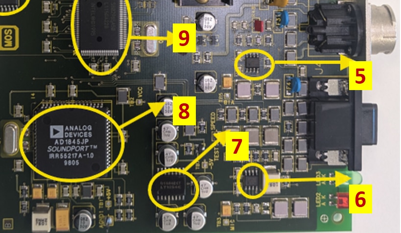
I am currently reverse-engineering a non-contact RPM sensor module that uses a Bosch knock sensor (
Knock Sensors (0261231046) - Knock Sensors - Bosch Auto Parts)
and a Condenser MIC output as the input. The knock sensor and MIC signal is fed into 2 separate op-amp
LMC66x CMOS Dual Operational Amplifiers datasheet (Rev. D)
, and the op-amp output goes to a CODEC
AD1845 , DigChip http://www.digchip.com
for processing.
My goal is to understand the op-amp circuitry and determine the appropriate configuration needed to condition the knock sensor and MIC signal before feeding it to the CODEC. I am a bit confused about where to start and what concepts I should study regarding op-amp. and there is a charge pump as well,
LT1054 Switched-Capacitor Voltage Converters With Regulators datasheet (Rev. G)
Could anyone guide me on:
How to analyze the existing op-amp circuit?
What op-amp configurations are commonly used for piezoelectric sensors such as knock sensors?
What topics should I study to better understand this signal-conditioning stage?
How can I determine the expected signal levels and bandwidth requirements before the CODEC input?
The ultimate task is to redesign this board while maintaining identical functionality and output behavior as the existing device, so understanding the analog front-end is critical.
Any suggestions on the right approach, reference materials, or debugging techniques would be greatly appreciated.
AI is confusing with too much data. Not getting a clear path.