


随着EDA技术的高速发展, 以大规模和超大规模器件FPGA/CPLD为载体、以VHDL(硬件描述语言)为工具的电子系统设计越来越广泛。有限状态机(简称状态机)作为数字系统控制单元的重要设计方案之一,无论与基于VHDL语言的其他设计方案相比,还是与可完成相似功能的CPU设计方案相比,在运行速度的高效、执行时间的确定性和高可靠性方面都显现出强大的优势。因此状态机在数字电子系统设计中的地位日益凸显。
1 状态机“毛刺”的产生
状态机通常包含主控时序进程、主控组合进程和辅助进程三个部分。其中,主控组合进程的任务是根据外部输入的控制信号和当前状态的状态值确定下一状态的取向,并确定对外输出内容和对内部其他组合或时序进程输出控制信号的内容。一方面,由于有组合逻辑进程的存在,状态机输出信号会出现毛刺——竞争冒险现象;另一方面,如果状态信号是多位值的,则在电路中对应了多条信号线。由于存在传输延迟,各信号线上的值发生改变的时间则存在先后,从而使得状态迁移时在初始状态和目的状态之间出现临时状态——毛刺。
例如,采用Moore型有限状态机方案对ADC0809采样过程实现控制,其主要程序如下:
begin
lock <=lock1;
process(current_state,eoc)
begin
case current_state IS
when st0=>ale<=‘0’;start<=‘0’;oe<=‘0’;lock1<=‘0’;
next_state <=st1;
when st1=>ale<=‘1’;start<=‘0’;oe<=‘0’;lock1<=‘0’;
next_state <=st2;
when st2=>ale<=‘0’;start<=‘1’;oe<=‘0’;lock1<=‘0’;
next_state <=st3;
when st3=>ale<=‘0’;start<=‘0’;oe<=‘0’;lock1<=‘0’;
if (eoc=‘1’) then next_state <=st3;
else next_state <=st4;
end if;
when st4=> ale <=‘0’;start <=‘0’;OE<=‘0’;lock1<=‘0’;
if (eoc =‘0’) then next_state <=st4;
else next_state <=st5;
end if;
when st5=> ale <=‘0’; start <=‘0’;oe<=‘1’;lock1<=‘0’;
next_state <=st6;
when st6=> ale <=‘0’; start <=‘0’; oe <=‘1’;lock1<=‘1’;
next_state <=st0;
when others=> ale <=‘0’; start <=‘0’;oe <=‘0’;lock1<=‘0’;
next_state <=st0;
end case;
end process;
process (clk)
begin
if (clk’event and clk =‘1”) then
current_state <=next_state;
end if;
end process;
process(lock1)
begin
if lock1=‘1’ and lock1’event then
regl<=d;
end if;
end process;
q<=regl;
……
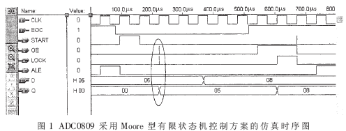
其时序仿真波形如图1所示。
http://www.eefocus.com/data/10-09/20755207050935/1283838883_f477ecb7.gif
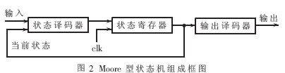
Moore型状态机组成框图如图2所示。
http://www.eefocus.com/data/10-09/20755207050935/1283838893_f2c646ef.gif
因为Moore型状态机的输出信号来自组合逻辑——输出译码器,输出信号中带有“毛刺”,且引起了输出信号Q的误动作,结果从其仿真时序图中可以发现。
2 毛刺的消除
在同步电路中,一般情况下“毛刺”不会产生重大影响。因为“毛刺”仅发生在时钟有效边沿之后的一小段时间内,只要在下一个时钟有效边沿到来之前“毛刺”消失即可。但当状态机的输出信号作为其他功能模块的控制信号,例如作为异步控制、三态使能控制或时钟信号使用时,将会使受控模块发生误动作,造成系统工作混乱。因此,在这种情况下必须通过改变设计消除毛刺。
消除状态机输出信号的“毛刺”一般可采用三种方案:
(1)调整状态编码,使相邻状态间只有1位信号改变,从而消除竞争冒险的发生条件,避免了毛刺的产生。常采用的编码方式为格雷码。它适用于顺序迁移的状态机。
(2)在有限状态机的基础上采用时钟同步信号,即把时钟信号引入组合进程。状态机每一个输出信号都经过附加的输出寄存器,并由时钟信号同步,因而保证了输出信号没有毛刺,如图3所示。这种方法存在一些弊端:由于增加了输出寄存器,硬件开销增大,这对于一些寄存器资源较少的目标芯片是不利的;从状态机的状态位到达输出需要经过两级组合逻辑,这就限制了系统时钟的最高工作频率;由于时钟信号将输出加载到附加的寄存器上,所以在输出端得到信号值的时间要比状态的变化延时一个时钟周期。
http://www.eefocus.com/data/10-09/20755207050935/1283838903_77b2006e.gif
(3)直接把状态机的状态码作为输出信号,即采用状态码直接输出型状态机,使状态和输出信号一致,使得输出译码电路被优化掉了,因此不会出现竞争冒险。这种方案,占用芯片资源少,信号与状态变化同步,因此速度快,是一种较优方案。但在设计过程中对状态编码时可能增加状态向量,出现多余状态。虽然可用CASE语句中WHENOTHERS来安排多余状态,但有时难以有效控制多余状态,运行时可能会出现难以预料的情况。因此它适用于状态机输出信号较少的场合。
若对ADC0809的采样控制采用状态码直接输出型状态机方案,其主要程序如下:
begin
lock<=lock1;
process(current_state,eoc)
begin
case current_state IS
when st0 => next_state <=st1;
when st1 => next_state <=st2;
when st2 => next_state <=st3;
when st3 => if (eoc =‘1’)then next_state <=st3; else next_state <=st4;end if;
when st4 => if (eoc =’0’)then next_state<=st4;else next_state <=st5; end if;
when st5 => next_state <=st6;
when st6 => next_state <=st0;
when others=> next_state <=st0;
end case;
out4<=current_state(5 downto 2);
ale<=current_state(5); start <=current_state(4);
oe<=current_state(3); lock1<=current_state(2);
end process;
process(clk)
begin
if (clk’event and clk =‘1’) then
current_state <=next_state;
end if ;
end process ;
process (lock1)
if lock1=‘1’ and lock1’event then
regl<=d ;
end if ;
end process ;
q<=regl;
……
http://www.eefocus.com/data/10-09/20755207050935/1283838918_7158712a.gif