


Currently I am playing with the ESP8266 WIFI module as many others are. Since I want to create some Arduino libraries for it, I am in the need to do some debugging. The Arduino only has one hardware UART. And if you wire anything to the atmega UART port you may run into problems when downloading new code to the Arduino. The Arduino programs the atmega via the hardware UART port and if something is connected it may cause trouble. For downloading you end up disconnecting and reconnecting the ESP module without mentioned that you loose the ability to use the Serial Console for debugging.
To solve this situation I now am using the SoftwareSerial library. Before all this I updated the ESP8266 firmware and the default baud rate is 9600 which is fine for the SoftwareSerial library.
My current setup is:
1. ESP8266 (ESP02) connected to a level shifter (to make 3.3V talks to the Arduino 5V). The level shifter I am using is a 74HC4050N hex non inverting buffer.
2. Wire pin 10, 11 via the level shifter to the ESP8266
3. Load a modified SoftwareSerial echo example to allow me to send serial commands from the Serial Monitor window to the ESP8266 via the arduino. Here is the link to the Arduino code for software echo.
I had it all wired without a level shifter but the SoftwareSerial library responded always like there were data available to receive when there were none. By using the level shifter all that "noise" went away and now I have a clean communication.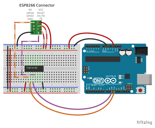
What the code do is just wait for anything from the UART serial port and sends it via the SoftwareSerial port (pins 10,11) and back. This way I can upload new code to the Arduino, talk to the ESP8266 and get debug messages via the Serial console without having to rewire things.
I am just starting to use this module, but it looks very interesting. Just wanted to share my current setup in case anyone wants to code for the Arduino and ran into the same problem I did.
Sorry that my diagram do not have a pretty ESP8266 module drawing but you get the idea. Use the legend above the green connector to match your module.
Update:
With this same thinking I decided to try a more "permanent solution". So I am in the process of building an interface prototype board for this module. I decided to build a dedicated interface circuit board (no breadboard prototype, straight to production). I blogged about it here if you care.
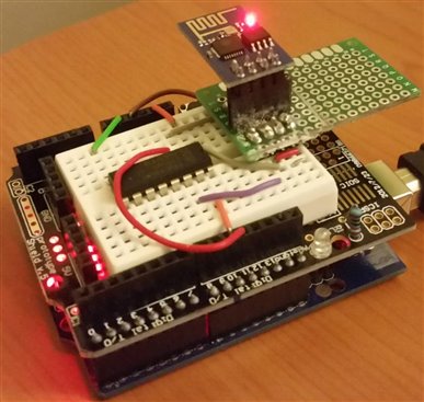
This is how this setup looks in real life:
Note:
Verify your Arduino version maximun 3.3V supply current. The official Arduino Uno R3 can supply something like 150mA tops and that is not enough to make the ESP8266 work always. It may power up but not much more. Arduino compatible boards or clones may have different hardware with more power ratings. If not available then my recommendation is to get an external power source or to reduce the 5V power to 3.3V.
Top Comments