


Many IoT devices use wireless methods to communicate with other devices or with host systems. Just as with DC power-rail signals, probing of RF signals should be done with as little noise and as non-invasively as possible and with the best possible signal fidelity. Effective probing opens the door to Wi-Fi and Bluetooth signal analysis with RF demodulation, vector signal analysis, and spectrum analysis.
Acquiring wireless signals typically isn't difficult with IoT devices. In many cases, wireless antennas are connected to the IoT's printed-circuit board (PCB) with U.FL connectors, which are ultra-small, surface-mount coaxial connectors. A U.FL connector on the IoT's PCB enables a clean, direct connection to the device's RF output.
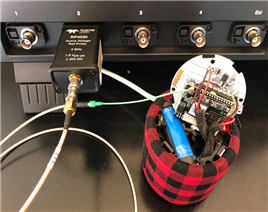
Figure 1: Many IoT devices accept wireless antennas using U.FL connectors
Teledyne LeCroy's RP4030 active voltage-rail probe is a good option for RF applications due to its low noise, high offset range, and 4-GHz bandwidth. Figure 1 depicts the RP4030 connected to the U.FL connector on an IoT device's PCB. In this case, 20-dB attenuators have been added to the front end of the RP4030 Probus interface to bring the signal within the probe's 1.6-V pk-pk dynamic range. The waveform can then be rescaled on the oscilloscope to reflect the true measurement of the acquired signal.
A typical IoT wireless IC supports various network standards, including IEEE 802.11 and Bluetooth, and will operate in the 2.4- and 5-GHz bands. There also are various modulation modes such as CCK and orthogonal frequency division multiplexing (OFDM) with PBSK, QPSK, 16 QAM, 64 QAM, and others for the engineer to validate.
Modern oscilloscopes can bring the following tools to bear on the RF validation challenge:
- Extensive set of analysis tools in the oscilloscope application for wireless signal characterization and debugging
- Vector signal-analysis software to analyze 802.11 and OFDM traffic
- Demodulation math function for amplitude, frequency, and phase demodulation
- Spectrum-analysis application for frequency-domain analysis and insight
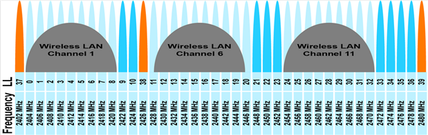
Figure 2: Bluetooth Low Energy slaves advertise on channels 37-39; BLE masters listen for these advertising packets and send a Connect Request to slaves
Let's look at Bluetooth Low Energy (BLE) advertising packets and how they might be analyzed using RF-burst amplitude and frequency demodulation. Referring to Figure 2, a BLE slave advertises on channels 37, 38, and 39, which are assigned to 2.402, 2.426, and 2.480 GHz, respectively. BLE channels are space 2 MHz apart. A BLE master listens for the advertising packets and sends a
Connect Request to a slave it wants to connect with.One metric we want to look at is how centered each of these packets are around its channel's mean frequency, and how much the spectral content is spread around that mean frequency.
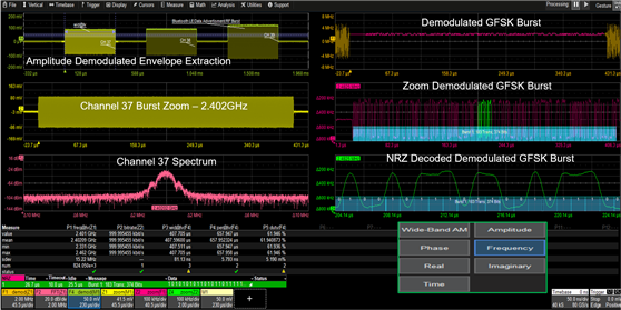
Figure 3: An amplitude-demodulated BLE advertising burst (shown in top-left grid above) reveals details regarding period, burst width, duty cycle, and more
Referring to Figure 3, the top-left grid shows the BLE advertising bursts. Using the oscilloscope's amplitude-demodulation math function, we can create a burst envelope waveform with which to measure the bursts's width, period, and duty cycle. These can be seen as the light-green trace bordering the burst envelope waveform.
The next grid down at left is a zoom trace of the Channel 37 burst. Below that in magenta is a fast-Fourier transform of that signal to measure its spectral content. Spectral analysis reveals that the burst is centered around 2.402 GHz and that most of its energy is contained within the desired 2-MHz bandwidth as expected.
The frequency demodulator math function can also be used on the GFSK-modulated burst to demodulate it into its serial-data bit stream (Figure 3, top right grid). The data can then be decoded to read the packet's preamble, axis, address, the advertising channel's header, and the packet's payload data directly on the oscilloscope.
Teledyne LeCroy's serial-data analysis software provides some extremely flexible capabilities, such as the length gate feature that enables performance of independent parallel analysis on each of the BLE advertising bursts simultaneously. The screen capture of Figure 4 shows Channel 37 on lane one, Channel 38 on lane two, and Channel 39 on lane three. We can view the spectrum of each RF burst and render eye diagrams of the frequency-demodulated data to analyze the signal quality of the underlying bit streams.
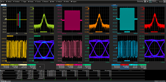
Figure 4: The length gate feature of Teledyne LeCroy's serial-data analysis software permits parallel analysis of each BLE advertising bursts simultaneously
In the measurement table at the bottom of Figure 4, we can find reports of the eye height, width, and peak-to-peak and RMS jitter, as well as other serial-data metrics that provide the user with deep insight into what's happening with their serial-data bit stream.
We'll continue looking into the RF aspects of IoT devices in our next post.
Previous blogs in this series: