


Table of Contents
Introduction
A friend had a need to monitor an outdoor device; it’s related to a watering system, and the output is a beeper. Unfortunately, the beeper is only loud enough to annoy the neighbors, but not loud enough to hear indoors! Definitely not fit for purpose.
The requirement was to somehow hear that alert indoors, and disable the outside beeper!
This blog post documents how I went about trying to solve this problem. There is no full project repository, it was a one-off circuit that ought to be redone significantly to improve on all the issues I found. There are plenty of bodges on the PCB, but I cannot see myself respinning this without majorly rethinking a lot of the circuit. However, the circuit I used is pasted within the blog, and all the (hopefully easy-to-port) code (the radio driver) is in a repository (it uses a custom 12-byte protocol).
There should be enough information here so others can see what to do and what not to do, to improve on this project and not make the mistakes I did.

Beep Sensing
I have no access to the watering system, I have not seen it nor measured anything, so I was working somewhat blind when developing this solution.
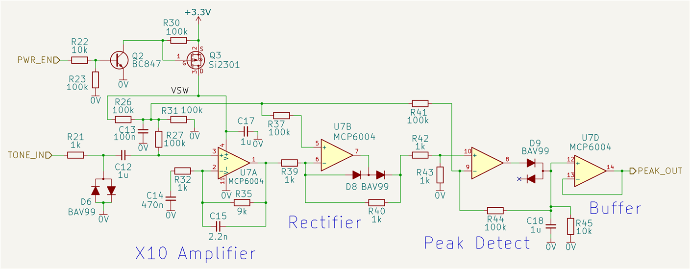
The circuit below shows what I used for the beep sensing, and since it is all done in the analog domain rather than in a microcontroller, it is easy to simulate if anyone is interested. The output is a voltage level that is representative of the amplitude of any incoming beep.
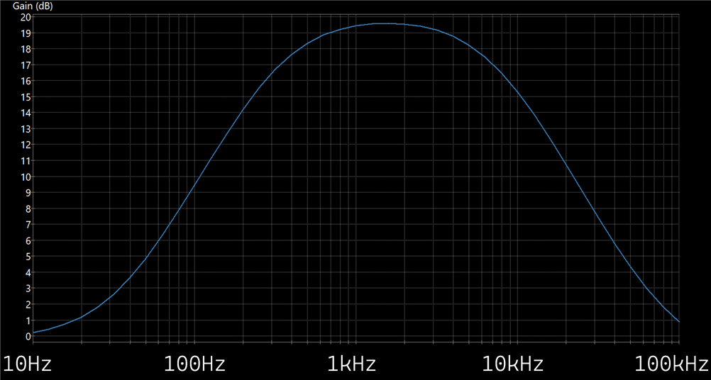
Here is the simulated frequency response of the first stage:
The ‘scope trace here shows the PEAK_OUT output, when the input (TONE_IN) is 0V.

If I apply a 100mV p-p 1 kHz signal (yellow) at the input, then the output (pink) rises to about 0.45V.

This is therefore quite a large output signal, easy to measure by the microcontroller ADC.
I need to support a large input range, because I have no idea what the system that this circuit will attach to will output.
If I apply a very large signal (5Vp-p, orange) at the input, I see a level of 1V output (yellow). Apologies for the inconsistent and wild colors, I’m still getting used to the reference traces in the new version of the PicoScope software.

Digital Sensing
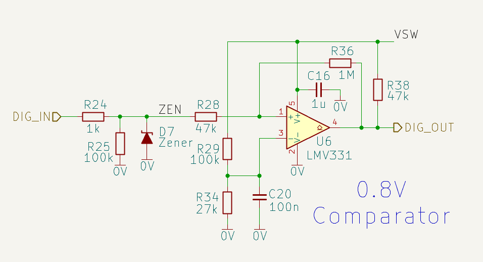
This part of the design was probably unnecessary, but I did it anyway, in case some future use comes up. By using a comparator, I can modify the levels/thresholds for unusual/unexpected scenarios. The configuration currently sets the output (DIG_OUT) at a low voltage when DIG_IN is below about 0.6V. DIG_OUT goes to approx. 3.3V when DIG_IN exceeds 0.8V (approx.).
Transmitter Circuit
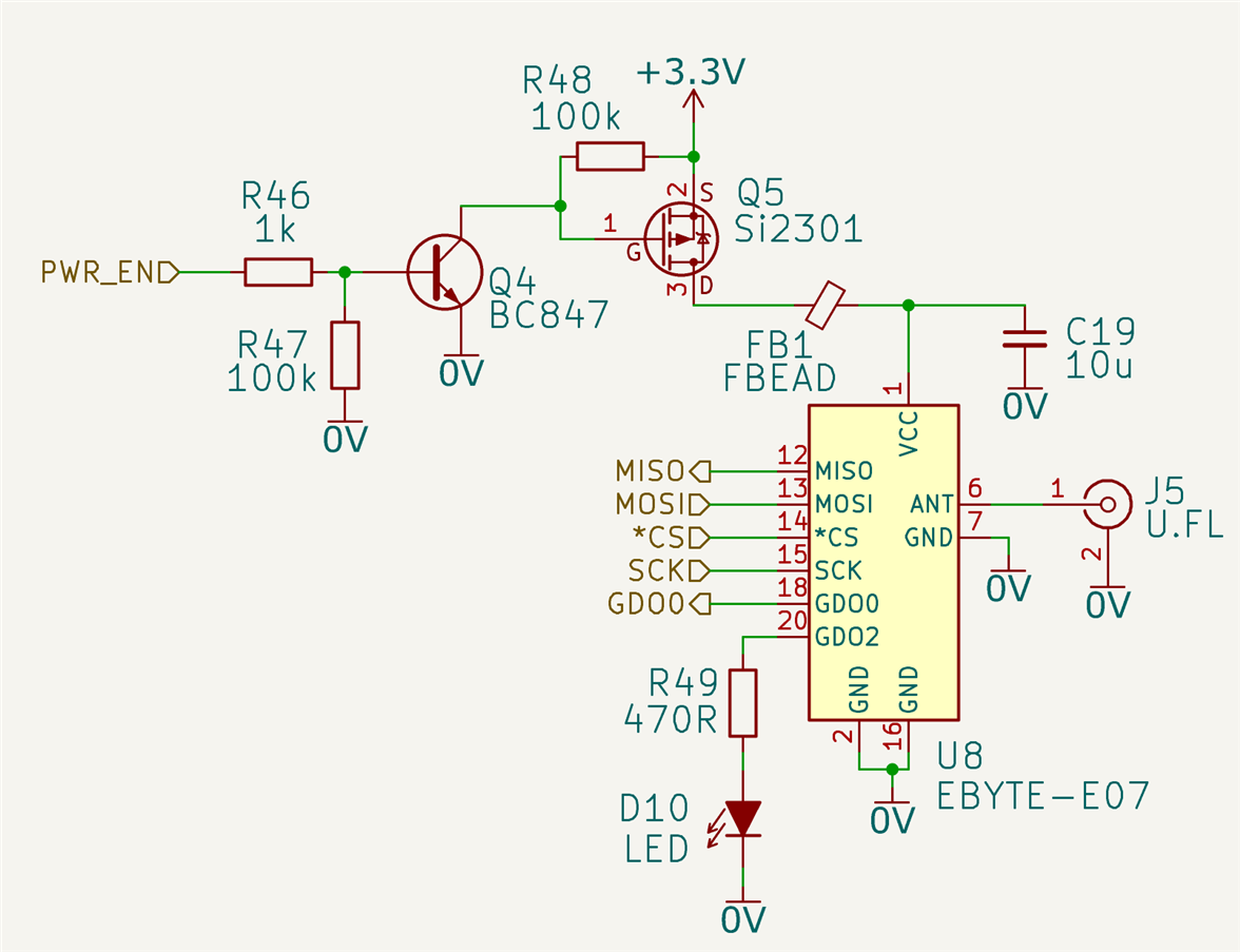
I decided to use the classic Texas Instruments CC1101 (PDF datasheet), which is available in module form. I had two good reasons: (1) The CC1101 has a very good level of configurability, useful if the project ever needs to interwork with different transmitters/receivers in future and (2) I was already using the CC1101 in another project so I reused my code.
The module that was used was Ebyte E07- 900MM10S (900 MHz) although technically the 433 MHz version might offer longer range. As it is, the 900 MHz version will easily cover the largest of gardens and residences, unless one owns a farm or castle. There’s a spare output pin on the CC1101, I connected that to a blue LED to indicate transmissions!
If I were to redo the project, I might give stronger consideration to using LoRa; there is an eByte LoRa module which is near-pin-compatible, but needs a few more signals. The modules are low-cost, one could even add both LoRa and CC1101 modules in a more future-proof design.
Microcontroller Circuit
This part of the circuit was the most challenging from my perspective, because I wanted it to be easy-to-use and configure, while at the same time being reasonably low-power. These requirements cause conflicts, because configuring a low-power circuit might not be possible when circuitry is asleep!
What I came up with is shown in the circuit below (click it to enlarge). It is mostly modelled on the EasyL1105 circuit.
The power to the entire board comes from the USB connector, or from a 5-15V external source, and a diode (D3) protects the USB interface from receiving current from the 5-15V source.
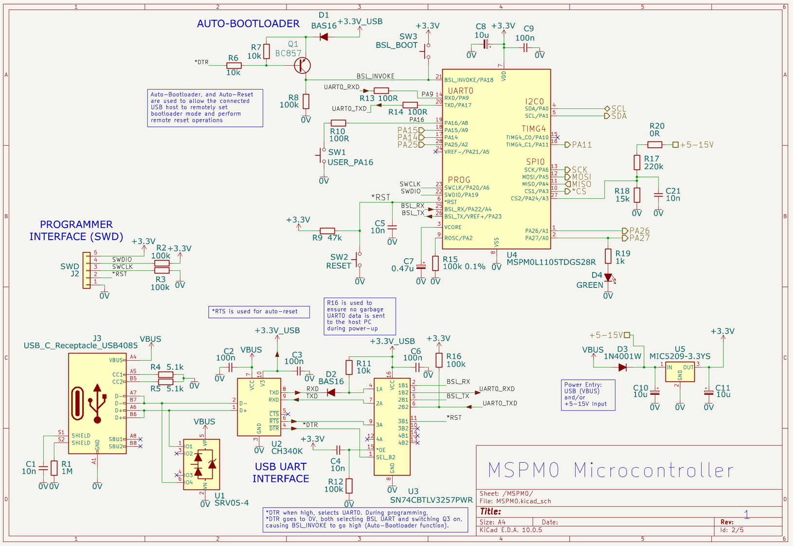
The MSPM0L1106 microcontroller has two UART interfaces, one of which, known as BSL, can be used to update the firmware. I used the other UART, known as UART0, to implement a configuration menu. A multiplexer/demultiplexer IC, U3, is used as an electronic switch to choose which of the two interfaces (BSL or UART0) should connect to the USB UART chip (U2).
I wanted to eliminate the need for button-presses and jumper connections, so the *RTS and *DTR lines are used to try to reset the microcontroller, and to put it into boot mode. I was only partially successful. As the circuit stands, it is certainly possible for a user to reprogram the chip by simply plugging the USB connector to a PC, and running mspm0_programmer software. That works great. However, the microcontroller needs to be restarted manually (either press a button, or power-cycle). That’s not good, but I’ve accepted it and moved on : (
Another issue is that with this circuit, the user cannot use any arbitrary serial terminal software to access the UART which runs a menu system. The serial terminal software must support the disabling of *DTR. TeraTerm is suitable, but others such as MobaXterm are not. In reality this is not too much of a problem, because I don’t expect users to use serial terminal software. I expect users to access the configuration through a custom graphical interface. The direct serial terminal menu is more for the advanced user.
Putting It All Together
The block diagram here shows how all the sub-circuits connect. The driver block at the top-right is unimportant, that’s just a MOSFET for optionally driving things in the future.

Software Overview
I decided to have three configurable parameters which define the periods for three important phases of the program operation; awake, receive, and sleep.
Awake Phase
During the awake time, the microcontroller can check the digital input, and perform ADC measurements, and if a threshold has been exceeded, then the radio module can be briefly set to transmit mode, to send an alert.
When the microcontroller begins the awake phase, it can send an empty radio message if there is no immediate alert to send.
Receive Phase
The receive phase overlaps the awake phase, they both commence at the same time, but the receive phase expires sooner.
The indoor receiver will be aware that the outdoor sender has just woken up because it will have seen either an alert packet, or an empty packet. This is therefore a good time for the indoor receiver to transmit any new config if desired.
As mentioned, the receive period starts when the awake period begins. The CC1101 is mostly in receive mode during that time, in case the indoor receiver wishes to transmit anything. After the receive period expires, but before the awake period expires, the code continues to check the ADC measurements and digital input, in case the CC1101 needs to be powered up to transmit an alert.
Sleep Phase
When the awake period is complete, the microcontroller powers down circuitry, sets a timer and goes to sleep. The digital input, and a button on the board can be used to wake up the microcontroller if desired before timer expiry.
Radio Driver / Protocol
The project uses a CC1101 simple driver that is generic, it should work with any microcontroller.
The CC1101 is configured to use GFSK modulation at a slow bitrate, since only 12 bytes of application data are used (I figured that would be sufficient for my needs). The 12 bytes contain a destination station identifier, version number, sequence number (so that packets can be repeated for a bit more reliability), a parameter identifier, and 4 bytes for the value.
Byte 0..1 : station_id (big-endian)
Byte 2    : flags/version
Byte 3    : sequence (useful to repeat packets for reliability)
Byte 4..5 : parameter_id (big-endian)
Byte 6..7 : reserved (big-endian)
Byte 8..11: value (big-endian)
If I were to do it again, I’d put more thought into the protocol. Perhaps change the parameter and value bytes into a more generic payload. A source identifier, and a packet type field would be a lot more flexible, and make it almost Ethernet-like (the CC1101 already adds preamble and a checksum).
There are existing protocols such as LoRaWAN (if I’d used a LoRa module), but I felt that was excessive for the application, and it requires more infrastructure.
Transmit Packets
Four different parameter identifiers are used in this project:
| Parameter ID | Description |
| Trigger Alert | Used to indicate if a threshold has been exceeded |
| Supply Alert | Used to indicate if the supply voltage is out-of-range (one of the ADC channels is attached to a potential divider wired to the supply input) |
| Button Alert | A user has pressed the button on the PCB |
| Idle Packet | Sent upon awake, if no other packet needs to be sent |
Receive Packets
In ordinary use no packets are expected to be sent from the indoors unit to the outdoor unit. However, I felt it worthwhile to allow configuration of all important variables, perhaps useful when initially setting up the system. Plus, the circuit board has a single Open Drain general-purpose output, and in future one might want to activate that remotely.
I randomly chose some parameter IDs, and used them for: GPOUT control, awake/receive/sleep interval setting, ADC thresholds setting, trigger mode (ADC and/or digital input) setting, station identifier and RX/TX frequency setting. So, in theory, the indoor unit can be used to tweak the outdoor unit settings, although in practise for the simple scenario that it is actually going to be deployed in, I’d expect the user to configure the outdoor unit settings using a USB cable plugged directly into the outdoor unit.
Depending on the microcontroller or hardware, it could be possible to store the configuration parameters in non-volatile memory; that’s what I did with the MSPM0, since it has a lot of Flash storage space.
User Menu
The unit has no display, and no essential buttons. The USB interface can become the primary method to configure the unit (although, as mentioned above, the radio interface can do that too). A limitation in the current design is that the microcontroller needs to be awake to access the user menu. It is easy to see that the microcontroller is awake because of on-board LEDs, or, the user could power-cycle the board and then immediately connect.
The menu uses GET/SET commands (e.g. SET awake_interval=600). However, the actual end user/installer is not an engineer, therefore I don’t expect them to fire up a serial terminal on the PC. Instead, they can use the AnyOperate app I worked on recently, for just this sort of scenario. It’s really convenient; using Android (for now; I don’t have a Mac to do the conversion for iPhone), one can connect to the outdoor unit via USB (or via USB, BLE or WiFi if connecting to the indoor unit) and configure it all from there. I’d like to modify that app to automatically pull templates from the web one day (that way the graphical display can be highly customized per project); today, all the config parameters are listed in a simpler manner (see the screenshot below) and the user just taps to select and modify.
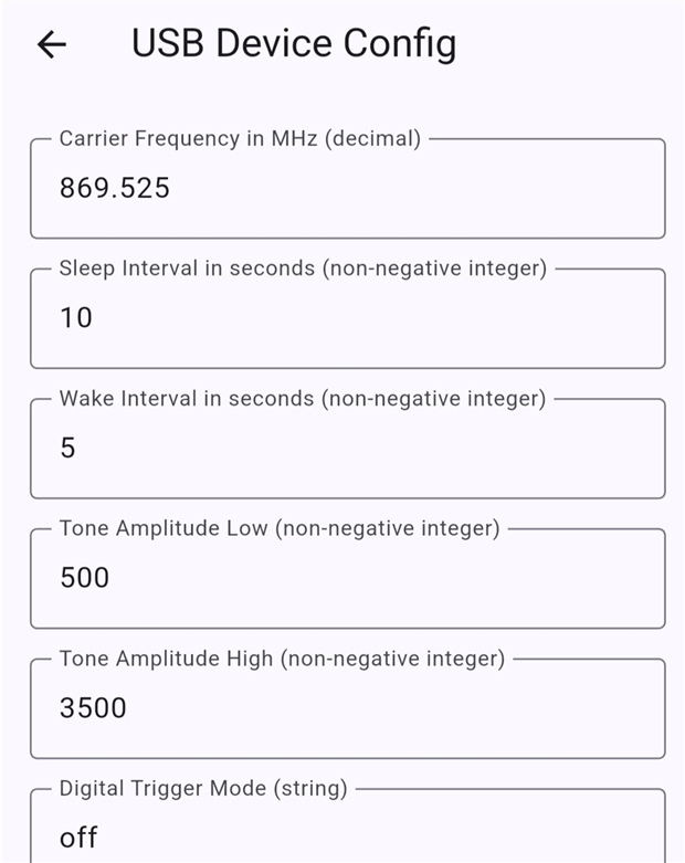
If you’ve got projects that are hard to configure or monitor for users, it could be worth giving AnyOperate a shot, and if you don’t like it, please suggest new features. There is a lot that could be done to improve it; so far, the software supports just some basics.
Power Measurements
For the intended use-case, I was not too concerned about making the project ultra-low-power; there is a solar panel plus battery outdoors, or alternatively, alkaline cells could be used; 4 x C cells might easily support a year of operation, i.e. $10 per year battery cost (and there’s no particular need for small size).
Here’s what I measured (at room temperature; it could be very different outdoors!):
| State | Current (mA) |
| Awake and transmitting and sensing | 49 |
| Awake and receiving and sensing | 27 |
| Awake and sensing | 5.6 |
| Sleeping | 0.195 |
The 195 uA sleep current can be broken down into:
| Circuit | Current (uA) |
| Source voltage monitoring potential divider | 20 |
| LDO (3.3V Regulator) | 95 |
| Microcontroller and associated connections | 80 |
In theory, the sleeping microcontroller should only consume about 1 uA I believe, however there is some current that will leak through some of the connections, plus, I may not have fully shut down all unused features, although I attempted to.
Sometimes, the lowest current consumption in sleep mode isn’t the bottleneck for decent battery performance. For the actual use-case for this project, if anything, it is the “sensing” current (guesstimating perhaps 4 mA, of the “awake and sensing” figure above) which will provide the greatest performance impact if that can be reduced further, because I believe the unit may need to be sensing for about a minute before sleeping for (say) 10 minutes, in case the tone alert that needs to be sensed only occurs once per minute (I am guessing).
Next Steps / Premature Project Post-Mortem
The circuit needs to be deployed : ) however, that’s unlikely to occur for a month or so. In the meantime, I will occasionally tweak the circuit or software, and leave it running from time to time.
It’s hard to know if the project was a success or not until it’s been in the field, however, some conclusions can already be made. The main things I’d change are:
(1) I don’t like JST PH connectors, the cables are unreliable without a ratchet crimping tool (the non-ratchet PA-09 tool is not really fit for purpose), and reliability is quite important for an outdoor project. The only reason I chose to use JST PH is because the existing system used that, and it would be handy to simply unplug the speaker and attach the cable to the transmitter.
(2) I’m not sure how wise it is to have USB connectors outdoors. That might become a big failure point (thankfully it is possible to configure over the radio, if that connector fails, although new firmware upgrades would become more difficult in the field). If this were a commercial project, I'd consider putting the USB connector on a separate PCB, so that it could be swapped out easily if it ever fails.
(3) I’d possibly use a different USB Serial chip; the CH340K (datasheet download link) has some quirks (see the discussion in the EasyL1105 blog; plus, you can see from the circuit diagram that I resorted to extracting a 3.3V supply from the chip, which is probably OK but technically unsupported) however there’s a learning curve with any new chip, and no guarantee everything would work first time with any other chip either; I’d also possibly consider just fitting two USB-C connectors and two USB Serial chips, one for firmware updates and the other for the user menu.
(4) Ultra-low power was not an initial consideration, but if I were to redo the project, I might look for a LDO with shutdown capability, or lower current operation.
(5) I’d focus more on the sensing circuit, to reduce the 5.7 mA current consumption in the “awake and sensing” mode; one simple low-hanging fruit change could be to separately enable power to the digital sensing portion, since mostly either ADC or digital sensing will be configured by the user, not both.
(6) It would maybe be better to use a PCB antenna, and have one less connector to fail.
Summary
An outdoor transmitter was designed, which attaches to speaker outputs, and detects alert sounds, and transmits the alert signal to an indoor unit. The very popular CC1101 transceiver chip was used (in module form) along with a low-cost MSPM0 microcontroller.
The radio protocol provides just a few bytes of payload. The protocol implements sequence numbers for increasing the reliability. The radio code is on GitHub, hopefully useful for any project that needs to transmit/receive a few bytes.
A user menu system was implemented, and made (hopefully) easy-to-use with a mobile phone app (AnyOperate; Android releases are available from the project repo). The software phases have configurable values for awake, receive and sleep periods, plus configurable thresholds for sense alerts and supply voltage faults.
Thanks for reading!
Top Comments