element14 Community
element14 Community
    Register Log In
  • Site
  • Search
  • Log In Register
  • Community Hub
    Community Hub
    • What's New on element14
    • Feedback and Support
    • Benefits of Membership
    • Personal Blogs
    • Members Area
    • Achievement Levels
  • Learn
    Learn
    • Ask an Expert
    • eBooks
    • element14 presents
    • Learning Center
    • Tech Spotlight
    • STEM Academy
    • Webinars, Training and Events
    • Learning Groups
  • Technologies
    Technologies
    • 3D Printing
    • FPGA
    • Industrial Automation
    • Internet of Things
    • Power & Energy
    • Sensors
    • Technology Groups
  • Challenges & Projects
    Challenges & Projects
    • Design Challenges
    • element14 presents Projects
    • Project14
    • Arduino Projects
    • Raspberry Pi Projects
    • Project Groups
  • Products
    Products
    • Arduino
    • Avnet Boards Community
    • Dev Tools
    • Manufacturers
    • Multicomp Pro
    • Product Groups
    • Raspberry Pi
    • RoadTests & Reviews
  • Store
    Store
    • Visit Your Store
    • Choose another store...
      • Europe
      •  Austria (German)
      •  Belgium (Dutch, French)
      •  Bulgaria (Bulgarian)
      •  Czech Republic (Czech)
      •  Denmark (Danish)
      •  Estonia (Estonian)
      •  Finland (Finnish)
      •  France (French)
      •  Germany (German)
      •  Hungary (Hungarian)
      •  Ireland
      •  Israel
      •  Italy (Italian)
      •  Latvia (Latvian)
      •  
      •  Lithuania (Lithuanian)
      •  Netherlands (Dutch)
      •  Norway (Norwegian)
      •  Poland (Polish)
      •  Portugal (Portuguese)
      •  Romania (Romanian)
      •  Russia (Russian)
      •  Slovakia (Slovak)
      •  Slovenia (Slovenian)
      •  Spain (Spanish)
      •  Sweden (Swedish)
      •  Switzerland(German, French)
      •  Turkey (Turkish)
      •  United Kingdom
      • Asia Pacific
      •  Australia
      •  China
      •  Hong Kong
      •  India
      •  Korea (Korean)
      •  Malaysia
      •  New Zealand
      •  Philippines
      •  Singapore
      •  Taiwan
      •  Thailand (Thai)
      • Americas
      •  Brazil (Portuguese)
      •  Canada
      •  Mexico (Spanish)
      •  United States
      Can't find the country/region you're looking for? Visit our export site or find a local distributor.
  • Translate
  • Profile
  • Settings
Open Source Hardware
  • Technologies
  • More
Open Source Hardware
Blog Building a USB-C USB-UART Board
  • Blog
  • Forum
  • Documents
  • Events
  • Polls
  • Members
  • Mentions
  • Sub-Groups
  • Tags
  • More
  • Cancel
  • New
Join Open Source Hardware to participate - click to join for free!
  • Share
  • More
  • Cancel
Group Actions
  • Group RSS
  • More
  • Cancel
Engagement
  • Author Author: shabaz
  • Date Created: 17 Feb 2022 1:41 AM Date Created
  • Views 19440 views
  • Likes 19 likes
  • Comments 17 comments
  • infineon
  • CY7C65213
  • cypress_semiconductor
  • cypress
  • usb-to-uart
  • opensource
Related
Recommended

Building a USB-C USB-UART Board

shabaz
shabaz
17 Feb 2022


Introduction


USB-UART devices provide an interface between a host computer and a peripheral device, connecting between the USB port and a serial connection called a serial UART. Nearly all microcontrollers have a serial UART, and sometimes it can be used for programming or debugging purposes.

image


I recently needed a new USB-UART device, and I took the opportunity to try out a USB-C connector, as well as upgrade from the usual USB-UART chip that I use, to a better one. In the past I used a MCP2221 based USB-UART. It is still great (simple to use) but it is missing (amongst other features) the hardware flow control which I really wanted. This time around I used a Cypress chip (now Infineon), based on a USB-UART datasheet comparison I'd worked on a few years ago.


The main features of this project are:
* Modern USB-C connector
* High transmission (baud) rates are supported (up to 3 Mbaud)
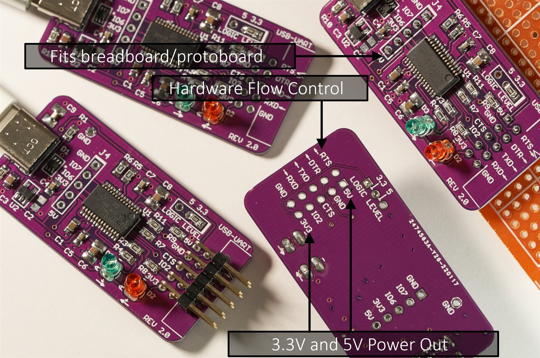
* 5V and 3.3V outputs for powering circuits
* 5V and 3.3V UART logic levels (a jumper or a slide switch can be fitted)
* Hardware Flow Control pins, RTS and CTS, are available
* 0.1 inch headers, for easy piggy-back connections onto other circuit boards
* Battery charge negotiation (BCS 1.2) capability pins are exposed for plug-on boards. See this Silabs RoadTest for some detail about BCS 1.2.
* Some GPIO pins are exposed
* Two LEDs for easily seeing if data is being received or transmitted

Circuit Diagram and Components

The circuit diagram is shown here; there is a PDF attached to the blog post.

(Note: I built a version 2.0, but the circuit and board files here are for a version 2.1 which is very slightly tweaked for easier hand-soldering and corrects the direction arrows on the LEDs):

image


The core of the circuit is the CY7C65213-28PVXI chip from Cypress Semiconductor.

Since there is a component shortage worldwide, it may be necessary to swap out the 3.3V regulator IC U2, for a pin-compatible alternative. If you do that, then the C2, C3 and C4 values will likely need modifying. There may be pin-compatible alternatives for D1 too. All resistors and capacitors can be 0805 sized, but 0603 size can fit too. C6, C8 and C9 component positions can accommodate 1210 sized capacitors if that is what is available.

The USB C connector is part code USB4085-GF-A and is straightforward to hand-solder (needs a 1mm diameter, or smaller, soldering iron tip, and 0.38mm diameter solder (or use solder paste). 

The 10-way right-angle connector can be T821110A1R100CEU or any generic DIL header should hopefully fit.

An ESD protection device, TPD4E1U06DCKR is used in the circuit, but it's hard to find due to the current shortage. Other SC70 sized ESD protection parts can be used. 


Building It

The circuit board layout is shown below; the files are attached to the blog post, ready for sending to a PCB factory.

image

For my use-case, I directly soldered a zero-ohm link at the logic level selector J2, to permanently set the board for 3.3V logic levels.

To build the board, I used a soldering iron, thin solder, flux, and desoldering braid to correct stuff. It could be reflow-soldered of course, but it wasn't necessary.

image

The board isn't designed to fit any particular enclosure, but something could be 3D-printed if desired.

image

Popular Boards Reference 


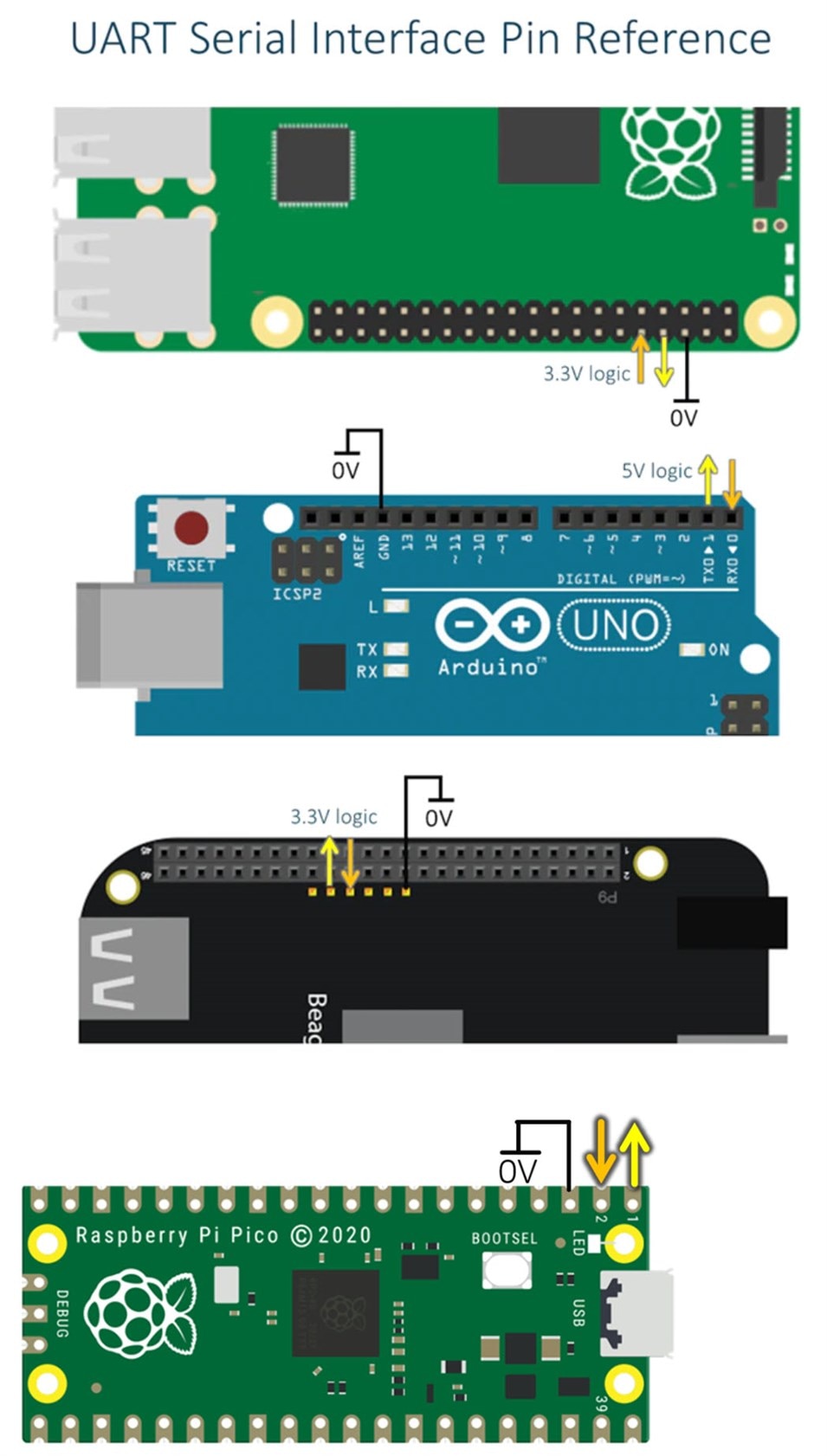
The diagrams below illustrate, using yellow and orange arrows, the board transmit and board receive directions respectively for some popular boards (Pi, Arduino, BeagleBone Black, and Pi Pico). See the photo further below to see where to connect the orange and yellow and black (ground) wires.

image


Using It


Currently I have only tested the RXD and TXD pins. I didn't need to install any driver on my Windows 11 PC, it just worked. It should work fine with Linux too. I also plugged it into two different Android phones, and successfully got a serial terminal app (from the Google Play Store) to function with it. Interestingly, the Samsung phone worked completely fine, whereas the Xiaomi phone had a popup appear which stated that the phone was not charging through the cable. I was able to clear the popup and use the USB-UART board fine, but I don't know why the popup appeared in the first place. The popup only appeared once, and didn't appear after unplugging and re-inserting the board.

The photo below shows how the basic RXD, TXD and Ground wires are connected.

image


It's nice finally being able to use the same USB-C cables that I use with the phone or PC, and I hope to use this board a lot. (Edit: six months on, and this is still the main USB UART board that I use).

The board files and schematic are attached. Thanks for reading!

usbc-uart-rev2_1-files.zip
  • Sign in to reply
  • embeddedguy
    embeddedguy over 1 year ago in reply to shabaz

    Thanks shabaz for your explanation. I would look for that

    • Cancel
    • Vote Up 0 Vote Down
    • Sign in to reply
    • More
    • Cancel
  • shabaz
    shabaz over 1 year ago in reply to embeddedguy

    I've seen the some USB-C lines being used for transporting unusual things like JTAG/SWD, but not seen that for UART. Maybe it's possible.

    However, it's probably best to just use a USB protocol (like CDC) rather than pure UART just to keep it standard. It's unusual to transport UART as-is over a connector, usually it's better to transport over (say) RS-232. In that case, USB-C connectors are not used of course, but DB-9 etc. However, another fairly compact connector is very suitable; modular connectors (i.e. RJ45-style). They work very well for RS-232 and are a standard for it, although maybe not as standard as DB-9.

    • Cancel
    • Vote Up 0 Vote Down
    • Sign in to reply
    • More
    • Cancel
  • embeddedguy
    embeddedguy over 1 year ago

    Hi shabaz ,

    I wanted to ask about USB-C. Recently, I was looking to design a PCB and in USB-C connector I saw Tx/Rx lines. The specification states that it can be used as alternate mode. ie. can be used for other protocols such as HDMI, media etc.

    Do you know weather these same pins can be used for UART?

    • Cancel
    • Vote Up 0 Vote Down
    • Sign in to reply
    • More
    • Cancel
  • shabaz
    shabaz over 1 year ago in reply to procrastin8

    Hi,

    There are various recommendations, for instance:

    image

    This following thread is useful, although still not 100% conclusive:

    https://www.eevblog.com/forum/beginners/usb-connector-design/

    I don't know practically if it makes a difference; that may require proper testing, and even then perhaps examining recalls from thousands of products in the field just in case the testing didn't reflect reality, depending on the device and enclosure and how it gets used.

    All I know is, I've always added those components, and have not come across any incompatibility by doing so, and (to the best of my knowledge) not damaged anything. Perhaps I'm just wasting two unnecessary components. Anyway, my comment here is effectively meaningless as a single datapoint, it would be different in an actual product. Personally, I'd add them to the board, since the footprints are zero-cost, and then you have the flexibility as mentioned in the information above.

    • Cancel
    • Vote Up 0 Vote Down
    • Sign in to reply
    • More
    • Cancel
  • procrastin8
    procrastin8 over 1 year ago

    Thank you for this write-up, I'm using it for the basis of my own USB-C powered design. That said, I was wondering what are the purposes of the cap from one shield pin to ground and the resistor from the other shield pin to ground? Not seeing any recommendations in the data sheet for this part around this.

    • Cancel
    • Vote Up 0 Vote Down
    • Sign in to reply
    • More
    • Cancel
>
element14 Community

element14 is the first online community specifically for engineers. Connect with your peers and get expert answers to your questions.

  • Members
  • Learn
  • Technologies
  • Challenges & Projects
  • Products
  • Store
  • About Us
  • Feedback & Support
  • FAQs
  • Terms of Use
  • Privacy Policy
  • Legal and Copyright Notices
  • Sitemap
  • Cookies

An Avnet Company © 2025 Premier Farnell Limited. All Rights Reserved.

Premier Farnell Ltd, registered in England and Wales (no 00876412), registered office: Farnell House, Forge Lane, Leeds LS12 2NE.

ICP 备案号 10220084.

Follow element14

  • X
  • Facebook
  • linkedin
  • YouTube