element14 Community
element14 Community
    Register Log In
  • Site
  • Search
  • Log In Register
  • Community Hub
    Community Hub
    • What's New on element14
    • Feedback and Support
    • Benefits of Membership
    • Personal Blogs
    • Members Area
    • Achievement Levels
  • Learn
    Learn
    • Ask an Expert
    • eBooks
    • element14 presents
    • Learning Center
    • Tech Spotlight
    • STEM Academy
    • Webinars, Training and Events
    • Learning Groups
  • Technologies
    Technologies
    • 3D Printing
    • FPGA
    • Industrial Automation
    • Internet of Things
    • Power & Energy
    • Sensors
    • Technology Groups
  • Challenges & Projects
    Challenges & Projects
    • Design Challenges
    • element14 presents Projects
    • Project14
    • Arduino Projects
    • Raspberry Pi Projects
    • Project Groups
  • Products
    Products
    • Arduino
    • Avnet & Tria Boards Community
    • Dev Tools
    • Manufacturers
    • Multicomp Pro
    • Product Groups
    • Raspberry Pi
    • RoadTests & Reviews
  • About Us
    About the element14 Community
  • Store
    Store
    • Visit Your Store
    • Choose another store...
      • Europe
      •  Austria (German)
      •  Belgium (Dutch, French)
      •  Bulgaria (Bulgarian)
      •  Czech Republic (Czech)
      •  Denmark (Danish)
      •  Estonia (Estonian)
      •  Finland (Finnish)
      •  France (French)
      •  Germany (German)
      •  Hungary (Hungarian)
      •  Ireland
      •  Israel
      •  Italy (Italian)
      •  Latvia (Latvian)
      •  
      •  Lithuania (Lithuanian)
      •  Netherlands (Dutch)
      •  Norway (Norwegian)
      •  Poland (Polish)
      •  Portugal (Portuguese)
      •  Romania (Romanian)
      •  Russia (Russian)
      •  Slovakia (Slovak)
      •  Slovenia (Slovenian)
      •  Spain (Spanish)
      •  Sweden (Swedish)
      •  Switzerland(German, French)
      •  Turkey (Turkish)
      •  United Kingdom
      • Asia Pacific
      •  Australia
      •  China
      •  Hong Kong
      •  India
      •  Japan
      •  Korea (Korean)
      •  Malaysia
      •  New Zealand
      •  Philippines
      •  Singapore
      •  Taiwan
      •  Thailand (Thai)
      •  Vietnam
      • Americas
      •  Brazil (Portuguese)
      •  Canada
      •  Mexico (Spanish)
      •  United States
      Can't find the country/region you're looking for? Visit our export site or find a local distributor.
  • Translate
  • Profile
  • Settings
Open Source Hardware
  • Technologies
  • More
Open Source Hardware
Blog Discrete difference amplifier - AC analysis: gain and bandwidth
  • Blog
  • Forum
  • Documents
  • Events
  • Polls
  • Members
  • Mentions
  • Sub-Groups
  • Tags
  • More
  • Cancel
  • New
Join Open Source Hardware to participate - click to join for free!
  • Share
  • More
  • Cancel
Group Actions
  • Group RSS
  • More
  • Cancel
Engagement
  • Author Author: Jan Cumps
  • Date Created: 14 Jul 2026 6:26 PM Date Created
  • Views 231 views
  • Likes 7 likes
  • Comments 11 comments
  • simple_dcr
Related
Recommended

Discrete difference amplifier - AC analysis: gain and bandwidth

Jan Cumps
Jan Cumps
14 Jul 2026

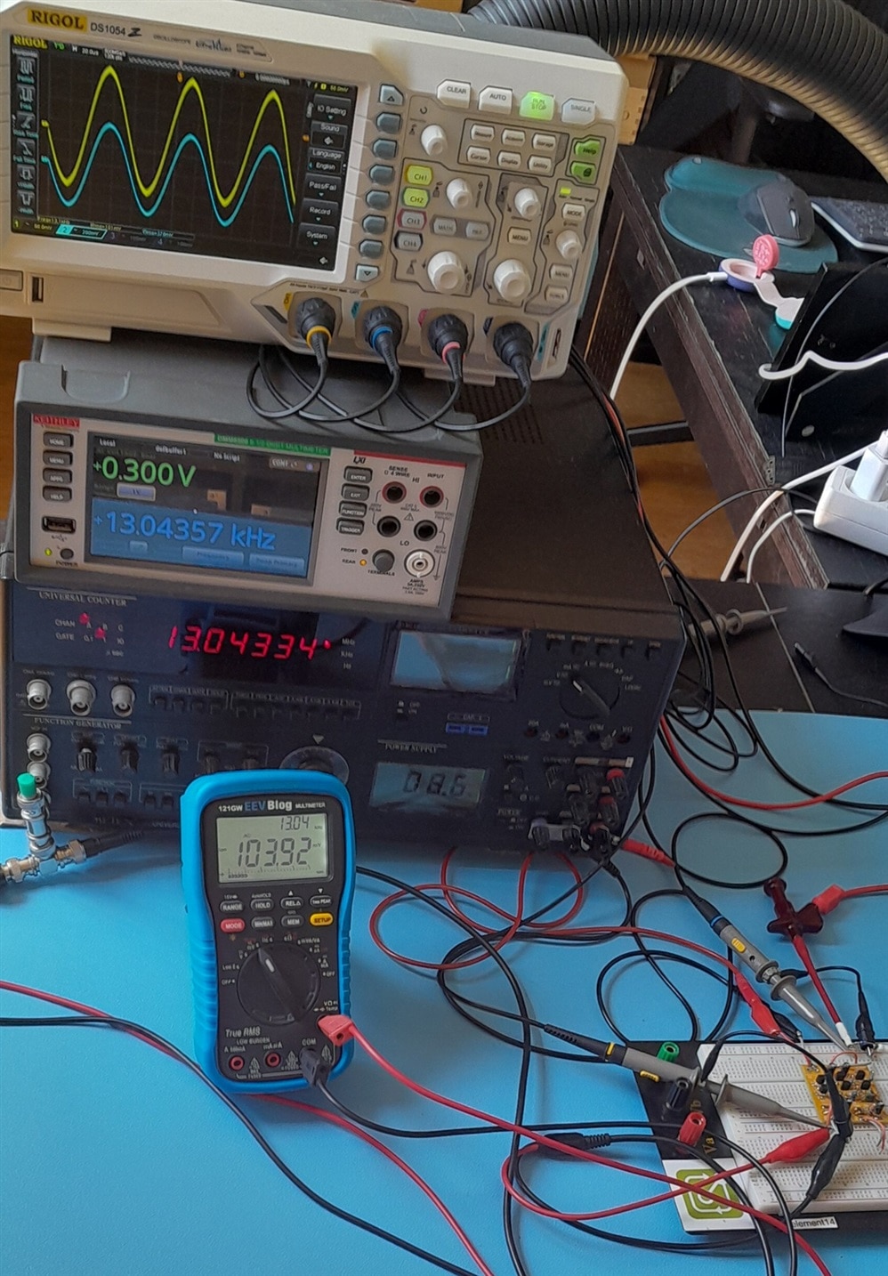
This is the AC gain and BW analysis of the difference amplifier module that shabaz designed for a Direct Conversion Receiver.

image

I'm searching for these points:

  • gain at 1 kHz (approx. mid of bandwidth)
  • -3 dB frequencies

I use Vrms values in the post - common for audio circuits. When measuring one of the differential channels, I tie the other to ground.
image

Specs:

  • Gain: ~10 dB
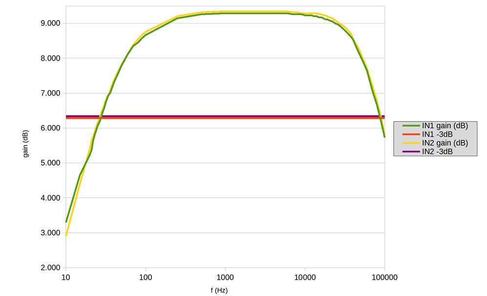
  • Bandwidth (-3 dB): ~30 Hz to 40 kHz (approximate)

Measurements:
image

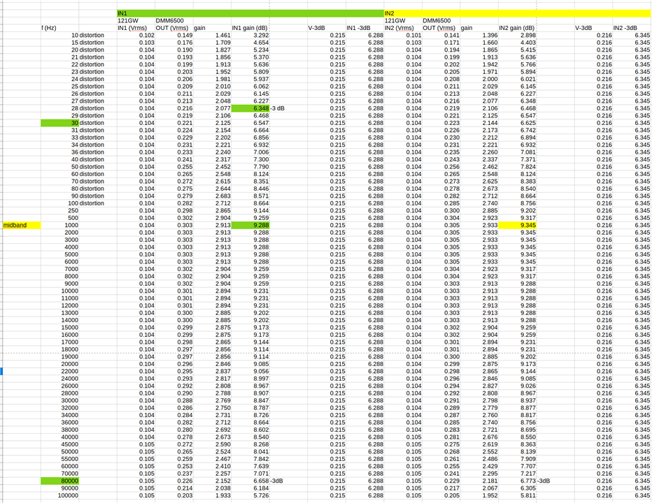
IN1: gain (1 kHz): 9.2 dB, bw (-3 dB): 30 Hz - 80 kHz

IN2: gain (1 kHz): 9.3 dB, bw (-3 dB): 30 Hz - 80 kHz
image

 shabaz published the KiCad project on GitHub, including simulation. You could load it into KiCad and check if the small signal simulation and my measurements match ...

For all blog posts in this series, click here

spreadsheet: differenceamp.zip

  • Sign in to reply
Parents
  • Jan Cumps
    Jan Cumps 19 days ago

     shabaz , the current source in the tail of the differential amp (orange area below):

    image

    what was your inspiration to design that sub-circuit that way?

    • Cancel
    • Vote Up 0 Vote Down
    • Sign in to reply
    • More
    • Cancel
  • shabaz
    shabaz 19 days ago in reply to Jan Cumps

    From memory I originally didn't have any of that, and used a resistor, but needed beyond a certain value to then be able to have lower gain and low distortion (since this stage wasn't intended to have high gain; I would have been happy with just 6 dB or so) but couldn't find a combination that would also give me a good signal input range (I needed at least several hundred mV to suit the circuitry preceeding it).

    Eventually I gave up and tried the BJT current sink, there may well be more optimal biasing that could have eliminated the need for the BJT sink at all, I just couldn't find it through trial-and-error (I'm not an analog designer otherwise I may have known a better technique). (By trial-and-error I mean using the KiCad simulator).

    Once I went down that road although I took some time on it, I believe better results could be achieved. I likely just started with one transistor and then for some reason switched to the darlington pair, but there are better current sink topologies. For the combination of relatively large input (few hundred mV p-p), what seemed like good common signal rejection, low desired gain and low distortion in the speech bandwidth, the tweaks had reached a point where the simulator results suggested there was no need to improve further.

    I was finding it took ages to find something optimal since there are two inputs and I'd have to keep changing the signals to check it was still working fine across these requirements.

    • Cancel
    • Vote Up +1 Vote Down
    • Sign in to reply
    • More
    • Cancel
  • jc2048
    jc2048 17 days ago in reply to shabaz

    "...since there are two inputs and I'd have to keep changing the signals..."

    Something that's handy for these kind of situations are the controlled sources in spice. Here I've got a voltage-controlled voltage source on the second input controlled by the generator on the first. If I set the controlled source gain to -1, then the second input is simply the inverse of whatever the generator is set to, and if I set the gain to 1, both inputs are the same and the second tracks the generator.

    image

    • Cancel
    • Vote Up 0 Vote Down
    • Sign in to reply
    • More
    • Cancel
  • Jan Cumps
    Jan Cumps 17 days ago in reply to jc2048

    First attempt to simulate the current source / sink:

    image

    • Cancel
    • Vote Up 0 Vote Down
    • Sign in to reply
    • More
    • Cancel
Comment
  • Jan Cumps
    Jan Cumps 17 days ago in reply to jc2048

    First attempt to simulate the current source / sink:

    image

    • Cancel
    • Vote Up 0 Vote Down
    • Sign in to reply
    • More
    • Cancel
Children
  • Jan Cumps
    Jan Cumps 15 days ago in reply to jc2048

    In LTSpice, with NPX BC547C model:

    image

    ... and the zoom:

    image

    • Cancel
    • Vote Up 0 Vote Down
    • Sign in to reply
    • More
    • Cancel
  • jc2048
    jc2048 16 days ago in reply to Jan Cumps

    I'd do it like this with Tina-TI. Here I've asked for a DC Transfer Analysis where it sweeps a generator between two voltages and plots the result. I imagine you'll be able to do something equivalent, because it's almost certain to be fundamental to the spice simulator.

    image

    The graph then shows the compliance of the source. Not very useful below 2V, but fine above, with a reasonably flat top.

    Below 0.5V the current goes negative, because there's a path back through the base-collector diode from the potential divider, but you can ignore that.

    This is with the vertical scale magnified so that you can see the slope better.

    image

    Keep in mind that that's coming from simplified transistor models in a simulator - so the real slope may be different, and may not even be a precise straight line like that.

    • Cancel
    • Vote Up +1 Vote Down
    • Sign in to reply
    • More
    • Cancel
element14 Community

element14 is the first online community specifically for engineers. Connect with your peers and get expert answers to your questions.

  • Members
  • Learn
  • Technologies
  • Challenges & Projects
  • Products
  • Store
  • About Us
  • Feedback & Support
  • FAQs
  • Terms of Use
  • Privacy Policy
  • Legal and Copyright Notices
  • Sitemap
  • Cookies

An Avnet Company © 2026 Premier Farnell Limited. All Rights Reserved.

Premier Farnell Ltd, registered in England and Wales (no 00876412), registered office: Farnell House, Forge Lane, Leeds LS12 2NE.

Follow element14

  • X
  • Facebook
  • linkedin
  • YouTube