element14 Community
element14 Community
    Register Log In
  • Site
  • Search
  • Log In Register
  • Community Hub
    Community Hub
    • What's New on element14
    • Feedback and Support
    • Benefits of Membership
    • Personal Blogs
    • Members Area
    • Achievement Levels
  • Learn
    Learn
    • Ask an Expert
    • eBooks
    • element14 presents
    • Learning Center
    • Tech Spotlight
    • STEM Academy
    • Webinars, Training and Events
    • Learning Groups
  • Technologies
    Technologies
    • 3D Printing
    • FPGA
    • Industrial Automation
    • Internet of Things
    • Power & Energy
    • Sensors
    • Technology Groups
  • Challenges & Projects
    Challenges & Projects
    • Design Challenges
    • element14 presents Projects
    • Project14
    • Arduino Projects
    • Raspberry Pi Projects
    • Project Groups
  • Products
    Products
    • Arduino
    • Avnet & Tria Boards Community
    • Dev Tools
    • Manufacturers
    • Multicomp Pro
    • Product Groups
    • Raspberry Pi
    • RoadTests & Reviews
  • About Us
  • Store
    Store
    • Visit Your Store
    • Choose another store...
      • Europe
      •  Austria (German)
      •  Belgium (Dutch, French)
      •  Bulgaria (Bulgarian)
      •  Czech Republic (Czech)
      •  Denmark (Danish)
      •  Estonia (Estonian)
      •  Finland (Finnish)
      •  France (French)
      •  Germany (German)
      •  Hungary (Hungarian)
      •  Ireland
      •  Israel
      •  Italy (Italian)
      •  Latvia (Latvian)
      •  
      •  Lithuania (Lithuanian)
      •  Netherlands (Dutch)
      •  Norway (Norwegian)
      •  Poland (Polish)
      •  Portugal (Portuguese)
      •  Romania (Romanian)
      •  Russia (Russian)
      •  Slovakia (Slovak)
      •  Slovenia (Slovenian)
      •  Spain (Spanish)
      •  Sweden (Swedish)
      •  Switzerland(German, French)
      •  Turkey (Turkish)
      •  United Kingdom
      • Asia Pacific
      •  Australia
      •  China
      •  Hong Kong
      •  India
      •  Korea (Korean)
      •  Malaysia
      •  New Zealand
      •  Philippines
      •  Singapore
      •  Taiwan
      •  Thailand (Thai)
      • Americas
      •  Brazil (Portuguese)
      •  Canada
      •  Mexico (Spanish)
      •  United States
      Can't find the country/region you're looking for? Visit our export site or find a local distributor.
  • Translate
  • Profile
  • Settings
Open Source Hardware
  • Technologies
  • More
Open Source Hardware
Blog MiniThermaDrive: Fun with 3D Printer Heating Elements - Part 1
  • Blog
  • Forum
  • Documents
  • Events
  • Polls
  • Members
  • Mentions
  • Sub-Groups
  • Tags
  • More
  • Cancel
  • New
Join Open Source Hardware to participate - click to join for free!
  • Share
  • More
  • Cancel
Group Actions
  • Group RSS
  • More
  • Cancel
Engagement
  • Author Author: shabaz
  • Date Created: 5 Nov 2025 4:03 PM Date Created
  • Views 597 views
  • Likes 9 likes
  • Comments 28 comments
  • MSPM0L1105
  • heat
  • MSPM0
  • easyL1105
  • thermistor
  • MiniThermaDrive
  • heater
  • MiniL1105
  • 3d-printer
Related
Recommended

MiniThermaDrive: Fun with 3D Printer Heating Elements - Part 1

shabaz
shabaz
5 Nov 2025

Table of Contents

  • Introduction
  • What can it be used for?
  • High-Level Design
  • Driver Board
  • Summary

Introduction

Ever wanted to heat something to a precise temperature? I have, but I initially didn’t know how to go about it.

3D printer spares are quite cheap, and, although I don’t own a 3D printer, I decided to order a cheap replacement heater element and temperature sensor (thermistor) from Amazon, to try to see if I could make use of them!

This short blog shows the first part of the hardware, just the first printed circuit board (this is a two-PCB project). There will be a Control Board and a Driver Board. I only cover the latter, i.e., the heater driver board, in this blog.

This is a joint project with Jan Cumps, with the various bits of software all created over a couple of weeks, working in our spare time. If you're interested in more of the background detail, search the site for the tag MSPM0, and there are lots of blogs showing how all the software sub-systems were developed.

image

What can it be used for?

The end aim was to heat up metal punches for making imprints onto leather, but the project is fairly general-purpose. A friend mentioned it could be used to heat up the bed of 3D printers too, for instance. This project could be used to heat up anything with a small volume (say a few cubic inches) to user-selectable temperatures up to say 150 degrees C. It could also be used for melting and tempering chocolate! For anything much larger, or for higher temperatures, the heater or the circuit or the algorithm (which will run on the control board, not covered in this Part 1 blog) would need to be adjusted.

High-Level Design

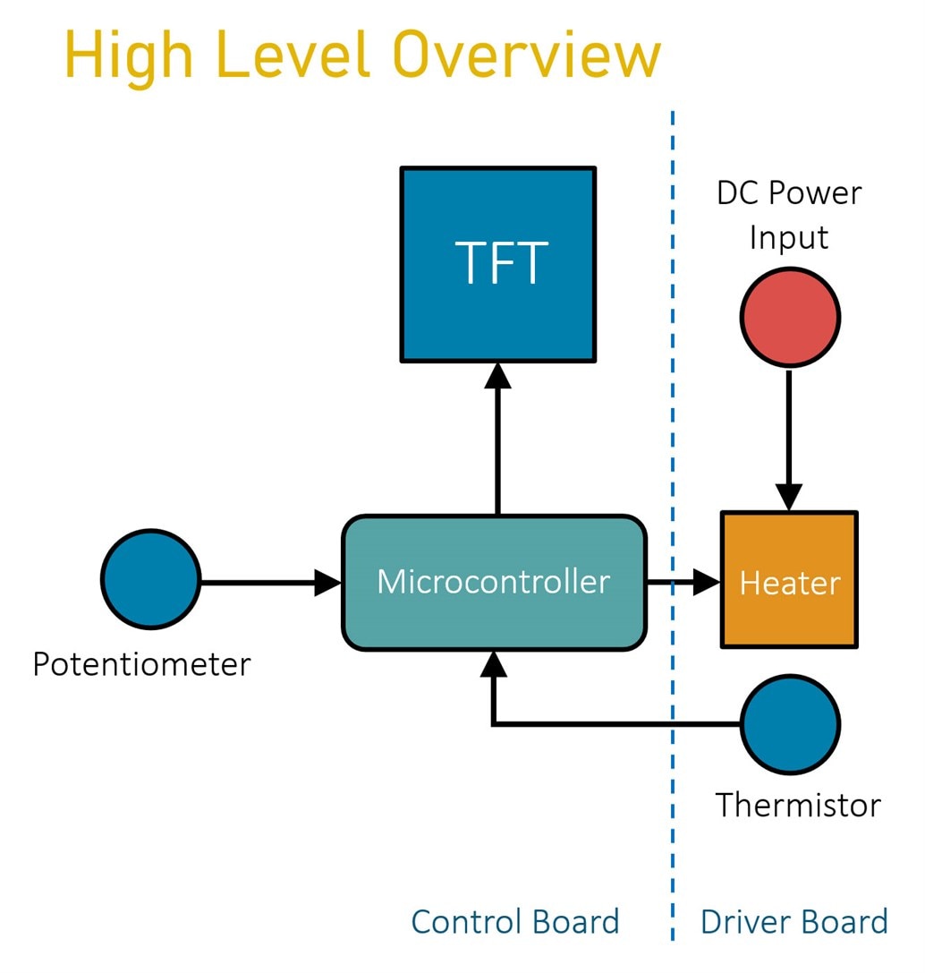
The diagram below shows what the solution will roughly look like. There will be a potentiometer to set the desired temperature, and a microcontroller will pulse power into the heating element using a MOSFET. The thermistor will be mounted close to the heater, and it will supply feedback to the microcontroller, so that the temperature can be kept stable using software control.

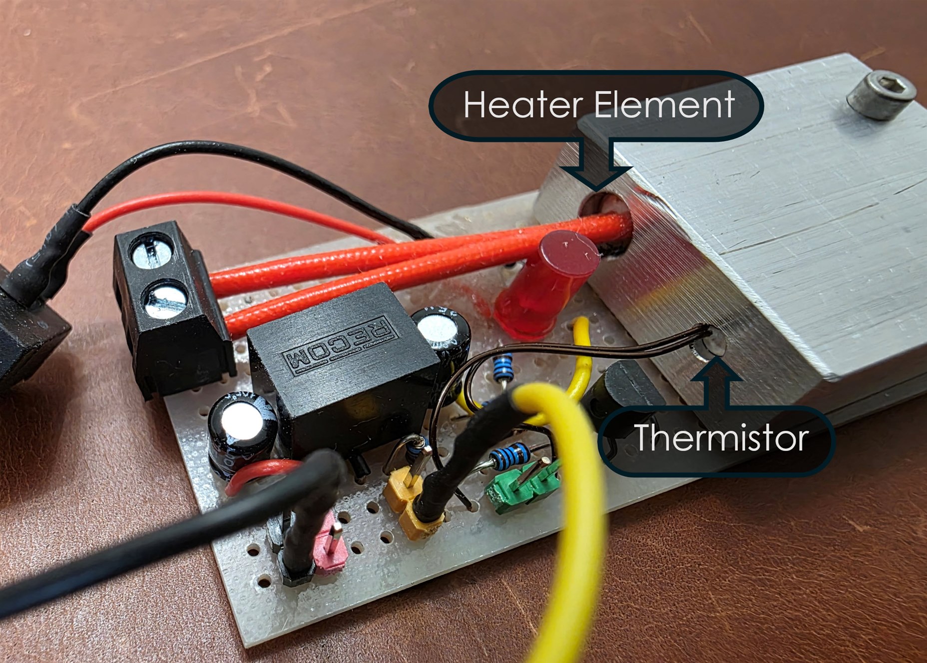
In the prototype photo at the top of the blog, you can see that the heater element and thermistor have been inserted into an aluminium block (which would either be the thing you’re trying to heat, or could be attached or pressed against the thing you’re trying to heat). The MOSFET is not visible in the photo, it was soldered to the underside in that prototype.

A small TFT screen can be used to display the potentiometer set temperature, and the actual temperature as measured by the thermistor.

image


As mentioned earlier, the hardware will be split up into two parts; this blog will simply cover the driver board.

Driver Board

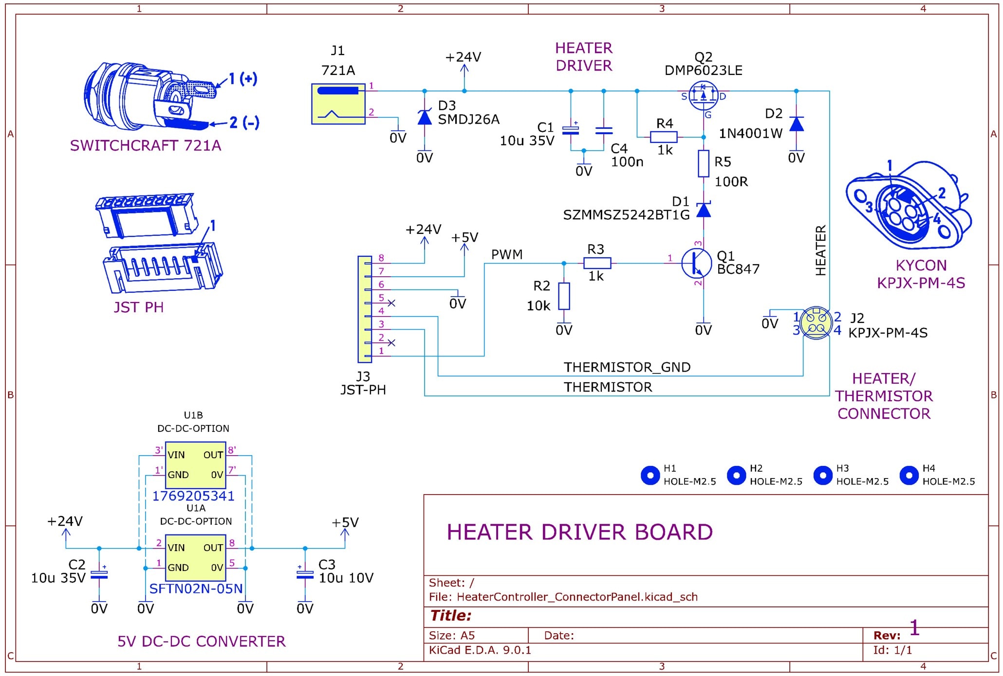
The diagram here shows what will be constructed. The circuit simply powers a heater using a MOSFET, so that 3.3V or 5V logic levels can be used to turn on the heater. The 24V DC input is also converted down to about 5V, so that it can be used to power the control board. An 8-pin JST connector is used to attach to the control board (I used this connector because ready-made interconnect cables are easily available at low cost from Amazon, so there’s no crimping tools or effort required.

For the heater and thermistor connection, there’s no standard that I’m aware of (I don’t own any 3D printers to confirm!), so I decided to use a low-cost latching 4-way connector.

image

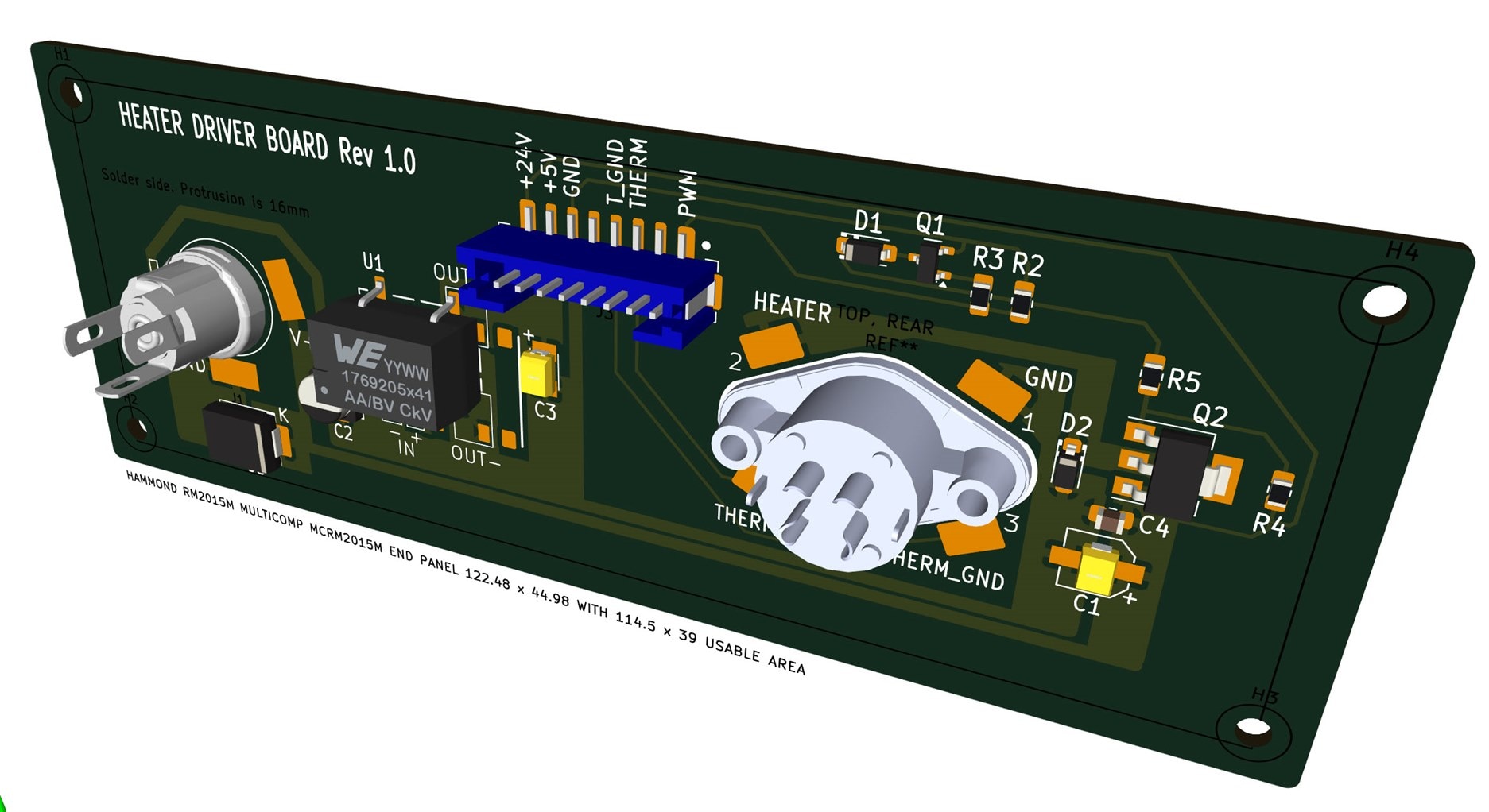
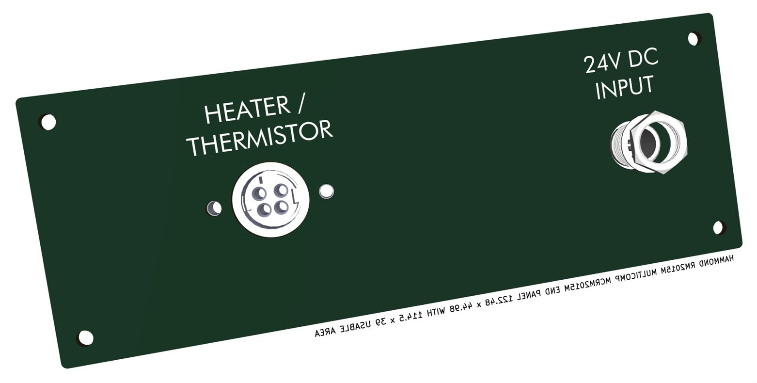
To simplify construction, the driver board performs double-duty as an end panel too, as shown below. This is not generally a wise thing, since there can be stresses when connectors are inserted or removed! However, I think it’s OK for this hobby project, and if there is any issue, then the connectors could simply be mounted on longer wires, onto a separately drilled front panel in the future.

The driver board will fit in a standard Hammond case or a Multicomp case, or an enclosure could be 3D-printed. The standard cases are unnecessarily large, so a 3D-printed case would be preferable. This project doesn’t have size constraints, so personally, I’m OK with using the ready-made case.

image

Here’s the other side of the panel:

image

The PCB trace layout is shown here, there are traces only on one side, to keep the other side looking like a front panel. All components used are large, so that the board is very easy to hand-solder.

image

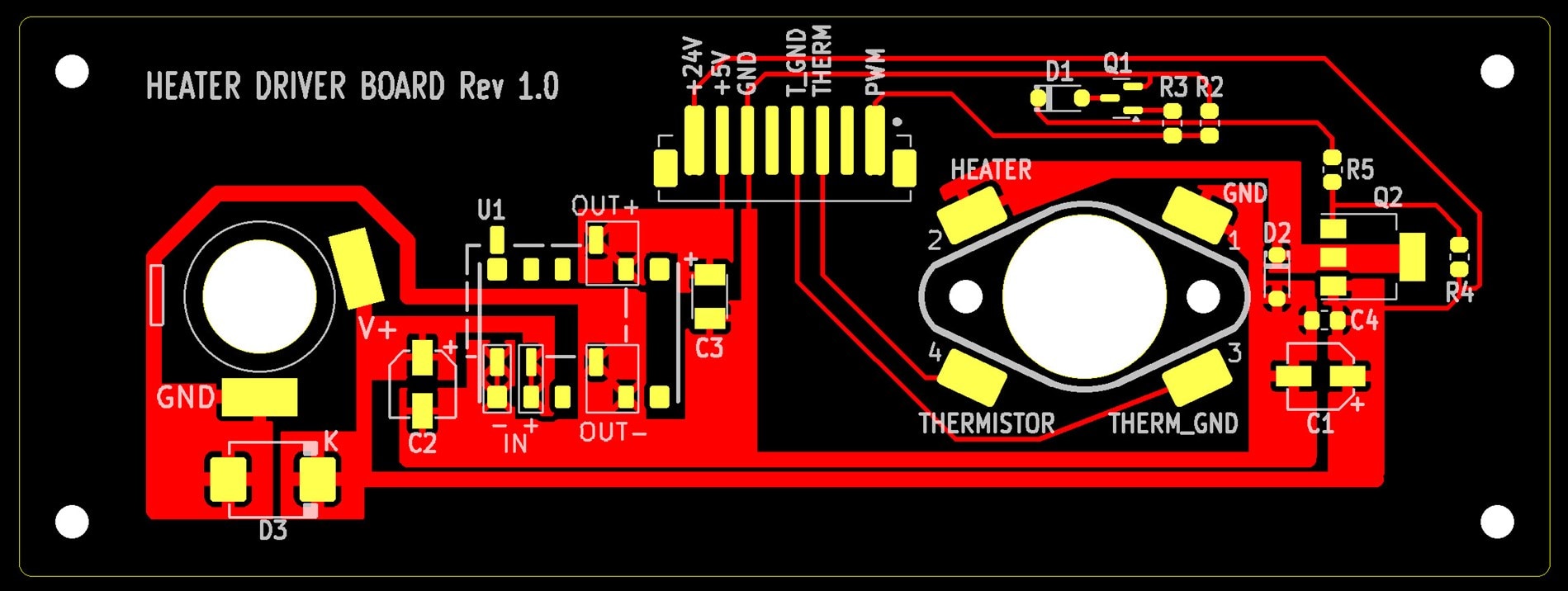
The KiCad files and Gerber files for the project are available at the MiniThermaDrive GitHub repository. If you wish to replicate the project, then the Gerber files can be submitted to any PCB manufacturer. The PCB is not currently tested, so please don’t assume it is error-free.

Summary

A small heating system has lots of applications for industrial and hobby purposes. 3D printer heating elements are available as spares at low cost, and this project aims to make use of them for user-configurable temperature settings. The driver board described in the blog post serves to power the heating element based on a logic-level signal from a microcontroller (which will be discussed in the next blog post). Any microcontroller could be used to control this driver board.

The project files are available at the MiniThermaDrive repository.

Thanks for reading!

  • Sign in to reply
Parents
  • shabaz
    shabaz 2 days ago

    Here's the draft schematic for the Control Board. I've not done the PCB design yet, so if anyone spots any errors or has suggestions, please let me know, it would be appreciated!

    EDIT: I'll bring out the I2C connections, so that the SPI TFT screen can optionally be replaced by an I2C LCD.

    image

    • Cancel
    • Vote Up 0 Vote Down
    • Sign in to reply
    • More
    • Cancel
  • Jan Cumps
    Jan Cumps 2 days ago in reply to shabaz

    I checked to see if all functions are connected to a compatible pin. Looks all correct.

    For the background LED: are you happy with the fixed intensity? You still have some PWM pins available if you'd want to control its brightness (would need a transistor/fet).

    • Cancel
    • Vote Up 0 Vote Down
    • Sign in to reply
    • More
    • Cancel
  • shabaz
    shabaz 2 days ago in reply to Jan Cumps

    Makes sense, I will add a transistor and connect to say PA10 for the backlight. There's no use-interface method to configure the brightness since the only input is the potentiometer, but perhaps some may want to adjust the brightness to a preset in code. 

    • Cancel
    • Vote Up 0 Vote Down
    • Sign in to reply
    • More
    • Cancel
Comment
  • shabaz
    shabaz 2 days ago in reply to Jan Cumps

    Makes sense, I will add a transistor and connect to say PA10 for the backlight. There's no use-interface method to configure the brightness since the only input is the potentiometer, but perhaps some may want to adjust the brightness to a preset in code. 

    • Cancel
    • Vote Up 0 Vote Down
    • Sign in to reply
    • More
    • Cancel
Children
  • Jan Cumps
    Jan Cumps 2 days ago in reply to shabaz

    you could use one of the 2 open drain (ODIO) pins PA0/1 - you'd not need the transistor. They can each sink 20 mA max (also happens to be the max for the backlight), and are 5V tolerant. They can be used as PWM outputs.
    (and break out the unused PA10 and PA11 as possible I2C pins)

    • Cancel
    • Vote Up 0 Vote Down
    • Sign in to reply
    • More
    • Cancel
  • shabaz
    shabaz 2 days ago in reply to Jan Cumps

    Ah, I saw that too late. Anyway, it's not too bad, it might be reusable for higher current if a different display and backlight is used in future.

    Also cleaned up the schematic a little bit.

    image

    • Cancel
    • Vote Up 0 Vote Down
    • Sign in to reply
    • More
    • Cancel
  • Jan Cumps
    Jan Cumps 6 hours ago in reply to shabaz

    > you could use one of the 2 open drain (ODIO) pins PA0/1 - you'd not need the transistor. They can each sink 20 mA max

    I was overenthusiastic here. See Jon's comment: https://community.element14.com/technologies/embedded/b/blog/posts/5v-and-10-ma-gpio-with-mspm0-open-drain-io?CommentId=de84c04b-181f-4ad9-b1b5-08051045a247

    • Cancel
    • Vote Up 0 Vote Down
    • Sign in to reply
    • More
    • Cancel
element14 Community

element14 is the first online community specifically for engineers. Connect with your peers and get expert answers to your questions.

  • Members
  • Learn
  • Technologies
  • Challenges & Projects
  • Products
  • Store
  • About Us
  • Feedback & Support
  • FAQs
  • Terms of Use
  • Privacy Policy
  • Legal and Copyright Notices
  • Sitemap
  • Cookies

An Avnet Company © 2025 Premier Farnell Limited. All Rights Reserved.

Premier Farnell Ltd, registered in England and Wales (no 00876412), registered office: Farnell House, Forge Lane, Leeds LS12 2NE.

ICP 备案号 10220084.

Follow element14

  • X
  • Facebook
  • linkedin
  • YouTube