


Table of Contents
Introduction
Modern Nickel-Metal Hydride (Ni-MH) cells pack a lot of power, are low-cost, easily available, and are relatively safe compared to other battery technologies! Many Ni-MH cells can retain their charge for a long time, and can be charged many times.
Each Ni-MH cell provides a voltage of about 1.2 V but varies slightly depending on the state of charge. This means that four cells can often directly power nominally 5V-operation circuits (many such circuits can operate within a +-10% range, i.e. 4.5 to 5.5 V).
This project implements a battery charger for four Ni-MH cells, charged as a single battery pack. I decided to use AA sized cells, which can support about 2.5 AH of capacity.
The charger circuit can be safely left connected to the battery indefinitely if desired*, and it will continually top up the battery as required.
For instance, you could use it with a circuit that could be operated from batteries whenever they had some charge, but the charger could be attached at any point, regardless of whether the circuit was running or not, and the batteries would charge; and as mentioned, the charger could be left connected indefinitely.
The diagrams below show some example ways of deploying it.

Note: For 9V PP3 charging, see this alternative project: Building a Nickel-Metal Hydride (NiMH) Charger
Circuit
I built a circuit to charge 9V batteries a while back, but I decided to make a simpler circuit for this 4 x AA project. Both this circuit, and the earlier 9V charger circuit, both use trickle-charging methods, but in different ways. The 9V circuit uses a constant current source which is turned off after 19 hours or if the battery overheats. I felt these those mechanisms were useful for small 9V batteries.
For this 4 x AA charger project, the circuit is a lot simpler, with no timer or over-temperature cut-out; the circuit is instead intended to be able to be left connected indefinitely. Instead of a constant current, I used a current-limited supply. The current and voltage is limited as described here:
Current Limit
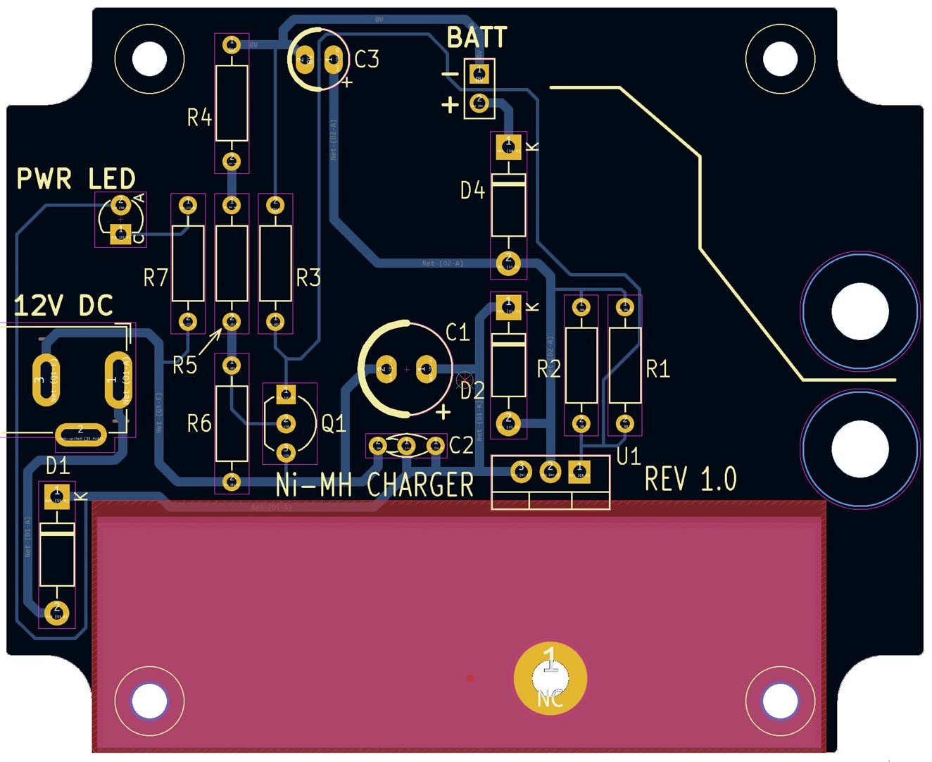
The circuit is approximately based on an example within the LM317 datasheet. The way it works, is that there is a small resistance in the negative connection (R4, R5 and R6). When the current through the connection increases, the voltage across R6 rises to 0.6V and causes the NPN transistor Q1 to switch on, which pulls the LM317 ADJ pin low. The LM317 tries to keep it’s output pin 1.25V higher than the ADJ pin, so as the ADJ pin voltage is reduced, this means the output voltage is reduced too.
With the values shown in the circuit diagram below, the current limit was set to about 220 mA. You can change the limit by changing R6; the current is approximately 0.6 / R6. Change R4 and R5 to be the same value as R6. For instance, if you want to set the limit to approximately 70 mA, set R4, R5, R6 to 8.2 ohm each.
Voltage Limit
By default (when current is lower than the limit) the output voltage from the LM317 will be 1.25 * (1 + (R3 / (R1//R2))) which is 6.45V. With a diode drop from D4, the output will be around 5.7V (but will vary slightly with current and temperature). This is a fraction on the high side for any 5V +- 10% specified connected circuitry, but there’s a good chance many such circuits will still work fine at 5.7V (it would need to be tested, since the manufacturer doesn’t specify what happens when operating outside the recommended range usually). If the connected circuit is more critical, then you could add a DC-DC converter to the system, as shown in the diagram at the start of this blog post, or perhaps even add a diode in series from the battery output to the attached circuit.

Building and Testing the Charger
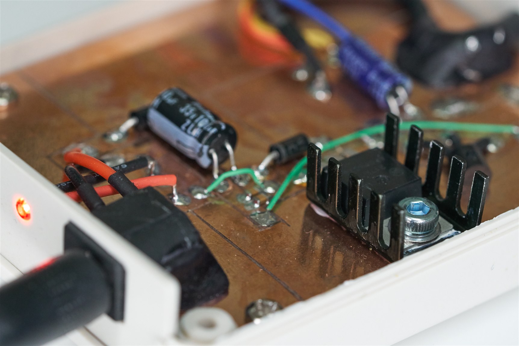
I built the prototype on copper-clad board. It fits in a low-cost enclosure from AliExpress.
When powered up (with no batteries attached) the output should be about 5.75V. Some basic tests can be done by applying a resistance to the output, and measuring the voltage and the current, and confirming that nothing overheats! It’s recommended to add a small heatsink to the LM317 (it doesn’t get very hot, so it doesn’t need to be a very large heatsink).

After that, I felt confident enough to attach four AA Ni-MH batteries (I tested with Ansmann 5035442 MaxE 2500mAH AA Ni-MH batteries). If you wish to also experiment with this project, then you could use the zipped-up PCB files and submit them to any PCB manufacturer.
It should look like this when assembled:

I used a data logger to measure the current and the charger voltage across the battery during charging.

As can be seen, starting with a fully discharged battery pack, the initial current was just over 200 mA, and over the space of a day, the current gradually reduced down to about 25 mA. With these current values, the battery can be charged indefinitely, without any significant degradation, for many years – hopefully! It’s yet to be seen.
Summary
Ni-MH battery technology is underrated, it still has uses despite being many decades old. It is possible to charge the batteries in a simple manner by restricting the maximum current to a low value, slowly charging over the space of about a day. A benefit of this is that it should be possible to leave the charger attached indefinitely. This lends itself to applications where the battery can be used for backup purposes after a power failure, or to applications where the user may wish to disconnect from the 12V adapter power source occasionally, and continue running the circuit with batteries.
Gerber files are available here.
Thanks for reading.
Disclaimer
* There’s no guarantee the circuit will work! If you spot errors with it, or things that could be improved, please mention below in the comments. I believe the circuit functions fine, but I cannot guarantee it, so you will be using it at your own risk.
-

shabaz
-
Cancel
-
Vote Up
0
Vote Down
-
-
Sign in to reply
-
More
-
Cancel
-

shabaz
in reply to shabaz
-
Cancel
-
Vote Up
0
Vote Down
-
-
Sign in to reply
-
More
-
Cancel
-

Jan Cumps
in reply to shabaz
-
Cancel
-
Vote Up
0
Vote Down
-
-
Sign in to reply
-
More
-
Cancel
Comment-

Jan Cumps
in reply to shabaz
-
Cancel
-
Vote Up
0
Vote Down
-
-
Sign in to reply
-
More
-
Cancel
Children