

.jpg)

|
I'm evaluating a Vishay microBRICK switch mode converter. The converter is Vishay's Reference Design for a 4.5 V to 60 V Input, 6 A, DC/DC Synchronous Buck Module SIC967 . One of my lab tests is to validate efficiency specs. In this post, a LabView flow is going to replicate a characteristic chart from the datasheet.
|
Efficiency test
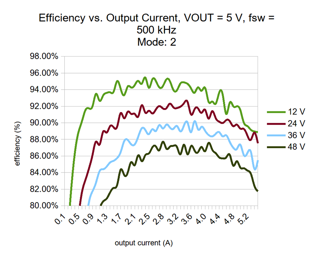
The SIC967 datasheet has a particular chart that's easy to replicate with the evaluation board: Efficiency vs. Output Current, with VOUT = 5 V, fsw = 500 kHz.
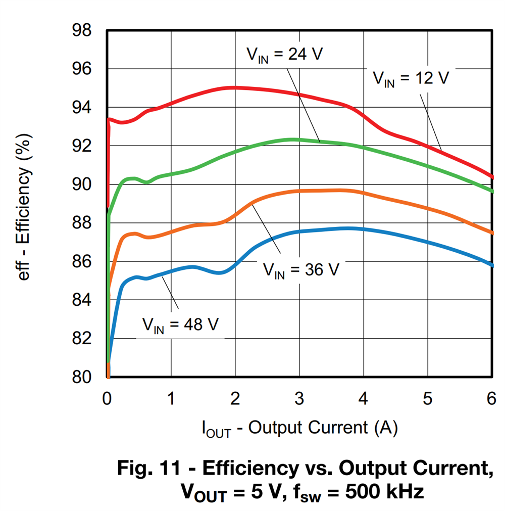
The chart shows the efficiency curve for output current between 0 and 6 A, for 4 different input voltages. This is one of the available setups of the kit.
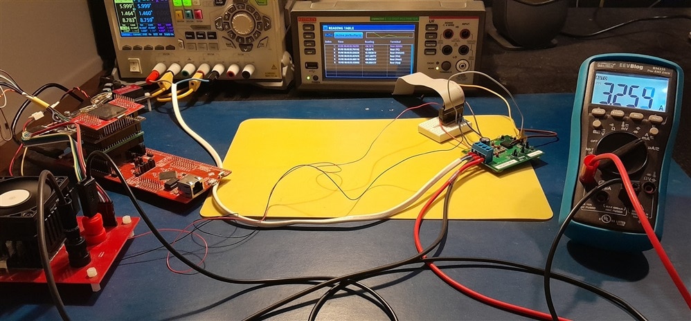
Bench setup
I'm using 3 instruments for this exercise. ALl are LabView capable:
- PSU: Rigol DP832A, with channel 1 and 2 in series
- Deliver Vin (12 - 24 - 36 - 48 V)
- Measure input current
- eLoad: my own
- draw current from the DUT, between 0.1 and 6 A
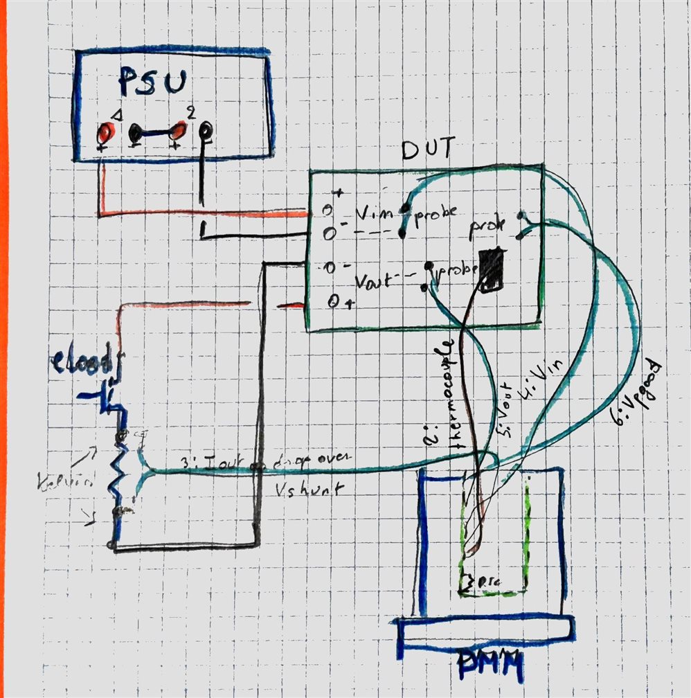
- Bench meter: Keithley DMM6500 with 2000-SCAN card (6 inputs used)
- 1: internal DMM temperature for cold junction compensation of channel 2
- 2: thermocouple attached to SIC967
- 3: Iout - measures the voltage drop over the kelvin terminals of the eLoad's shunt resistor
- 4: Vin at the DUT's probe points
- 5: Vout at the DUT's probe points
- 6: Vpowergood at the DUT's probe points
LabView
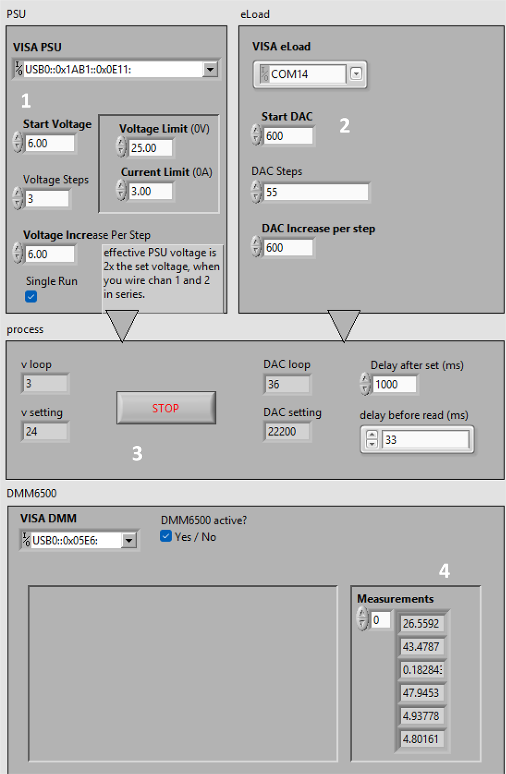
- PSU settings
- eLoad settings
- execution progress
- bench meter results
Setup
Initially, the flow connects to the 3 instruments and sets them up:
PSU:
Set Channel 1 and 2 to 0V, set current and Over Voltage limits, and set them as tracking, This will take care that when the flow changes the voltage of Channel 1, channel 2 follows along.
I've done that because 1 and 2 are in series to be able to deliver 48 V. The channels are switched on.
eLoad:
I'm using the low level direct DAC write API of the load. The load is set to draw 0 A, and activated.
Bench meter:
The first 6 channels of the scanner card are configured:
- Temperature, RTC, Pt100: measures the point where the thermocouple is connected to the card - the cold junction
- Temperature, Thermocouple, K-type: measures the switch IC case temperature
- Volt, 1 V dc: measures the shunt resistor of the eLoad. We 'll divide this value by 0.05 Ohm to get output current.
- Volt, 100 V dc: measures the input voltage at point of load
- Volt, 10 V dc: measures the output voltage at point of load
- Volt, 10 V dc: measures the power good signal
Flow
- Loop through the input voltage, from 12 to 48 volt. In 12 V increments
- Loop through the output currents, from 100 mA to 6A, in 55 steps
- get input current from the PSU
- get the 6 measurements from the bench meter
- write data points to an excel file
- Loop through the output currents, from 100 mA to 6A, in 55 steps
It's a big flow. Here's the little excerpt where the bench meter samples the 6 channels, all at once:
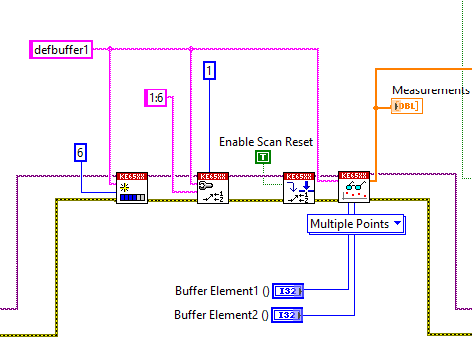
The complete project is attached to this post.
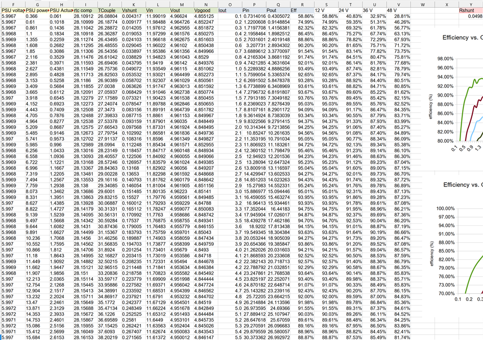
Results
Spreadsheet: Column A - > N are generated by the LabView flow. O -> R are calculations based on them. S -> V are the results put in a matrix for the chart below.
I made the Rshunt value configurable. Although it's close to 0.05R, it drifts a little based on its temperature. And the impact on efficiency accuracy is significant.
The spreadsheet is attached.
Graph: compare it with the graph from the datasheet at the beginning of this post
Thank you for reading
Top Comments