element14 Community
element14 Community
    Register Log In
  • Site
  • Search
  • Log In Register
  • About Us
  • Community Hub
    Community Hub
    • What's New on element14
    • Feedback and Support
    • Benefits of Membership
    • Personal Blogs
    • Members Area
    • Achievement Levels
  • Learn
    Learn
    • Ask an Expert
    • eBooks
    • element14 presents
    • Learning Center
    • Tech Spotlight
    • STEM Academy
    • Webinars, Training and Events
    • Learning Groups
  • Technologies
    Technologies
    • 3D Printing
    • FPGA
    • Industrial Automation
    • Internet of Things
    • Power & Energy
    • Sensors
    • Technology Groups
  • Challenges & Projects
    Challenges & Projects
    • Design Challenges
    • element14 presents Projects
    • Project14
    • Arduino Projects
    • Raspberry Pi Projects
    • Project Groups
  • Products
    Products
    • Arduino
    • Avnet Boards Community
    • Dev Tools
    • Manufacturers
    • Multicomp Pro
    • Product Groups
    • Raspberry Pi
    • RoadTests & Reviews
  • Store
    Store
    • Visit Your Store
    • Choose another store...
      • Europe
      •  Austria (German)
      •  Belgium (Dutch, French)
      •  Bulgaria (Bulgarian)
      •  Czech Republic (Czech)
      •  Denmark (Danish)
      •  Estonia (Estonian)
      •  Finland (Finnish)
      •  France (French)
      •  Germany (German)
      •  Hungary (Hungarian)
      •  Ireland
      •  Israel
      •  Italy (Italian)
      •  Latvia (Latvian)
      •  
      •  Lithuania (Lithuanian)
      •  Netherlands (Dutch)
      •  Norway (Norwegian)
      •  Poland (Polish)
      •  Portugal (Portuguese)
      •  Romania (Romanian)
      •  Russia (Russian)
      •  Slovakia (Slovak)
      •  Slovenia (Slovenian)
      •  Spain (Spanish)
      •  Sweden (Swedish)
      •  Switzerland(German, French)
      •  Turkey (Turkish)
      •  United Kingdom
      • Asia Pacific
      •  Australia
      •  China
      •  Hong Kong
      •  India
      •  Korea (Korean)
      •  Malaysia
      •  New Zealand
      •  Philippines
      •  Singapore
      •  Taiwan
      •  Thailand (Thai)
      • Americas
      •  Brazil (Portuguese)
      •  Canada
      •  Mexico (Spanish)
      •  United States
      Can't find the country/region you're looking for? Visit our export site or find a local distributor.
  • Translate
  • Profile
  • Settings
Power & Energy
  • Technologies
  • More
Power & Energy
Blog LabView process to measure DC:DC converter efficiency
  • Blog
  • Forum
  • Quiz
  • Documents
  • Polls
  • Events
  • Mentions
  • Sub-Groups
  • Tags
  • More
  • Cancel
  • New
  • Share
  • More
  • Cancel
Group Actions
  • Group RSS
  • More
  • Cancel
EMI-Reduction-Techniques
Engagement
  • Author Author: Jan Cumps
  • Date Created: 4 Jan 2025 11:49 PM Date Created
  • Views 1737 views
  • Likes 10 likes
  • Comments 8 comments
  • RoadTest
  • dc-dc
  • vishay
  • 2000-scan
  • dmm6500
  • smps
  • keithley
  • labview
Related
Recommended

LabView process to measure DC:DC converter efficiency

Jan Cumps
Jan Cumps
4 Jan 2025

I'm evaluating a Vishay microBRICK switch mode converter. The converter is Vishay's  Reference Design for a 4.5 V to 60 V Input, 6 A, DC/DC Synchronous Buck Module SIC967 . One of my lab tests is to validate efficiency specs. In this post, a LabView flow is going to replicate a characteristic chart from the datasheet.

image

Efficiency test

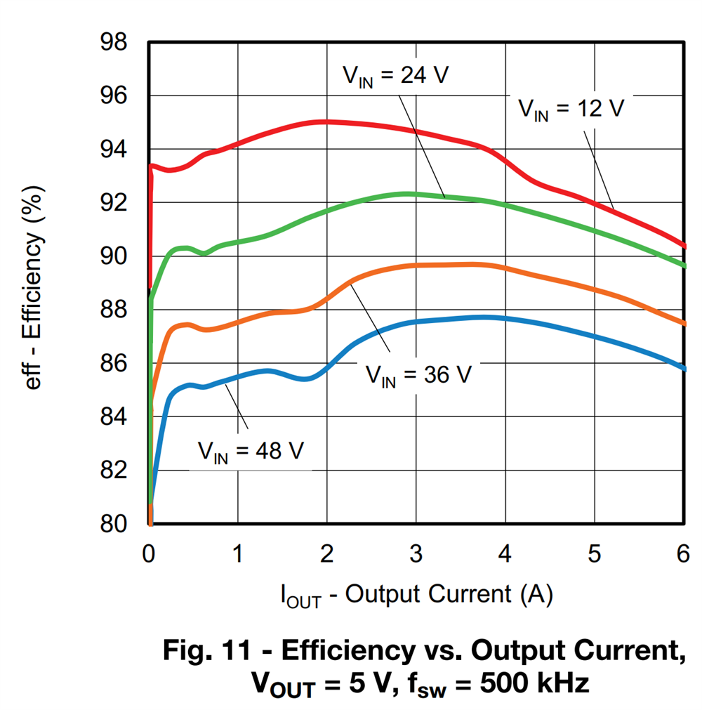
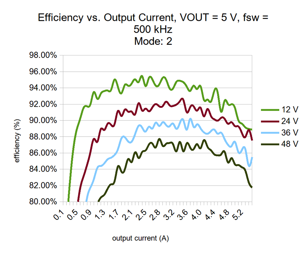
The SIC967 datasheet has a particular chart that's easy to replicate with the evaluation board: Efficiency vs. Output Current, with VOUT = 5 V, fsw = 500 kHz.
image

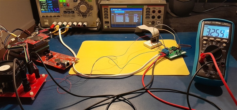
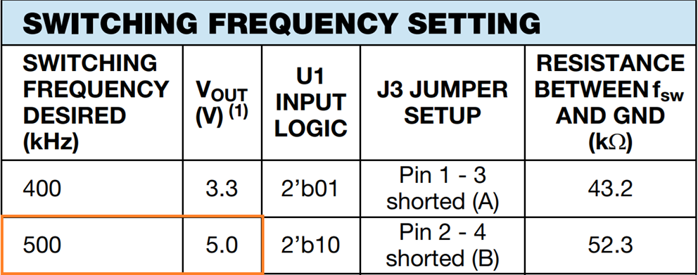
The chart shows the efficiency curve for output current between 0 and 6 A, for 4 different input voltages. This is one of the available setups of the kit. 
image

Bench setup

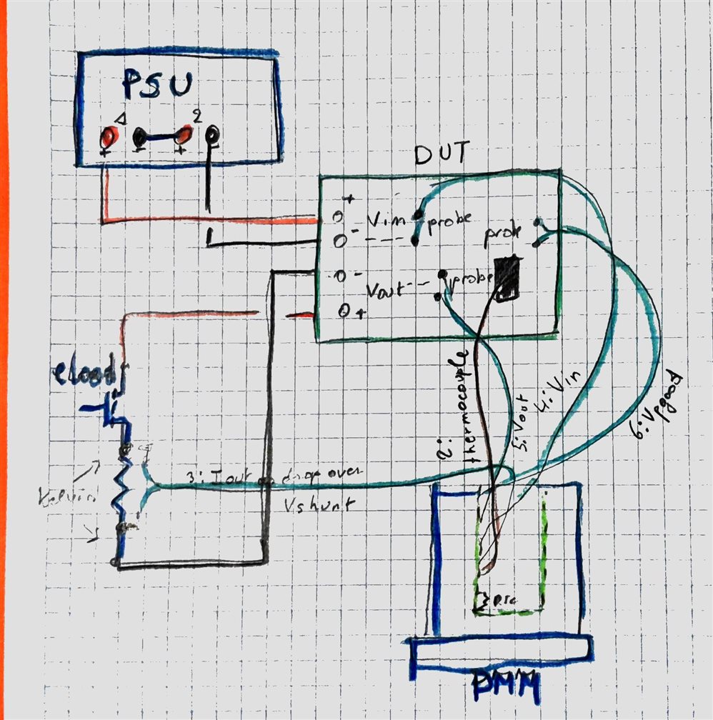
I'm using 3 instruments for this exercise. ALl are LabView capable:

  • PSU: Rigol DP832A, with channel 1 and 2 in series
    • Deliver Vin (12 - 24 - 36 - 48 V)
    • Measure input current
  • eLoad: my own
    • draw current from the DUT, between 0.1 and 6 A
  • Bench meter: Keithley DMM6500 with 2000-SCAN card (6 inputs used)
    • 1: internal DMM temperature for cold junction compensation of channel 2
    • 2: thermocouple attached to SIC967
    • 3: Iout - measures the voltage drop over the kelvin terminals of the eLoad's shunt resistor
    • 4: Vin at the DUT's probe points
    • 5: Vout at the DUT's probe points
    • 6: Vpowergood at the DUT's probe points
image

LabView

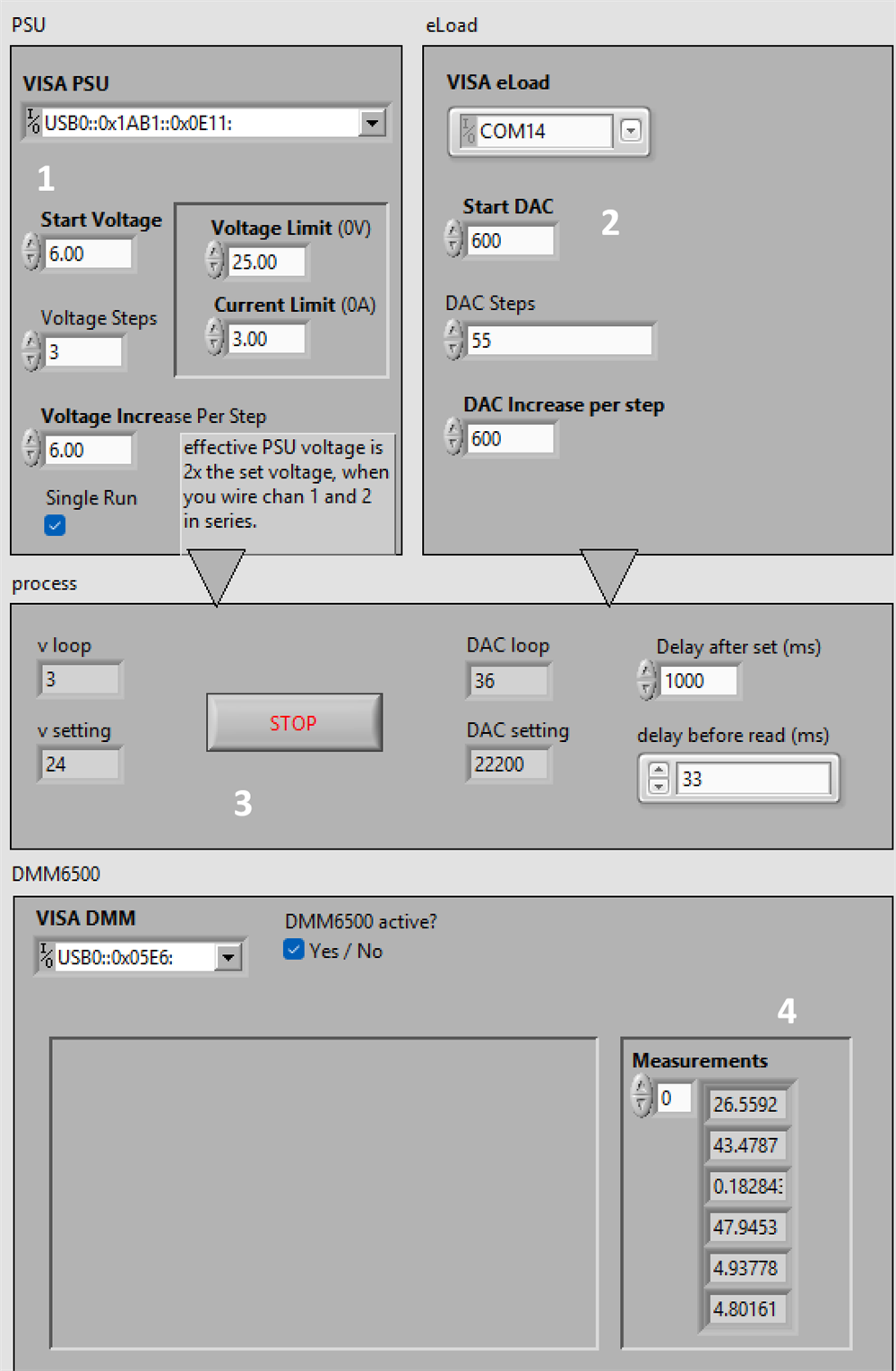
image

  1. PSU settings
  2. eLoad settings
  3. execution progress
  4. bench meter results

Setup

Initially, the flow connects to the 3 instruments and sets them up:

PSU:

Set Channel 1 and 2 to 0V, set current and Over Voltage limits, and set them as tracking, This will take care that when the flow changes the voltage of Channel 1, channel 2 follows along.
I've done that because 1 and 2 are in series to be able to deliver 48 V. The channels are switched on.

eLoad:

I'm using the low level direct DAC write API of the load. The load is set to draw 0 A, and activated.

Bench meter:

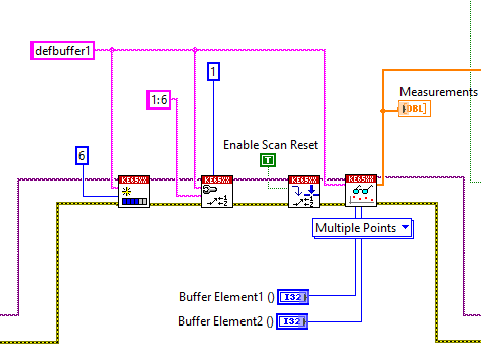
The first 6 channels of the scanner card are configured:

  1. Temperature, RTC, Pt100: measures the point where the thermocouple is connected to the card - the cold junction
  2. Temperature, Thermocouple, K-type: measures the switch IC case temperature
  3. Volt, 1 V dc: measures the shunt resistor of the eLoad. We 'll divide this value by 0.05 Ohm to get output current.
  4. Volt, 100 V dc: measures the input voltage at point of load
  5. Volt, 10 V dc: measures the output voltage at point of load
  6. Volt, 10 V dc: measures the power good signal

Flow

  • Loop through the input voltage, from 12 to 48 volt. In 12 V increments
    • Loop through the output currents, from 100 mA to 6A, in 55 steps
      • get input current from the PSU
      • get the 6 measurements from the bench meter
      • write data points to an excel file

It's a big flow. Here's the little excerpt where the bench meter samples the 6 channels, all at once:
image

The complete project is attached to this post.

Results

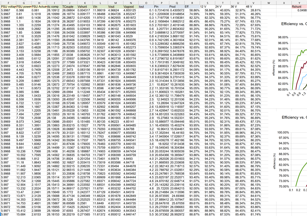
Spreadsheet: Column A - > N are generated by the LabView flow. O -> R are calculations based on them. S -> V are the results put in a matrix for the chart below.
I made the Rshunt value configurable. Although it's close to 0.05R, it drifts a little based on its temperature. And the impact on efficiency accuracy is significant.

The spreadsheet is attached.
image

Graph: compare it with the graph from the datasheet at the beginning of this post
 image

Thank you for reading

measureefficiency_35.zip

labview.zip

  • Sign in to reply

Top Comments

  • Jan Cumps
    Jan Cumps 7 months ago in reply to JWx +1
    Except for the Rigol oscilloscope, all instruments that I used have USB that does not share ground with the measurement leads / probes. I relied on that. I didn't use an isolator, just one of those very…
  • Jan Cumps
    Jan Cumps 7 months ago in reply to JWx +1
    additional warning: I used an extension card in my bench meter. It turns it from 1 channel into 10 channels. These are all 10 isolated from each other . 2 relays per channel take care that one channel…
Parents
  • JWx
    JWx 7 months ago

    Nice setup! I am thinking about building something like this (using GNU Octave as a controller)... I have a question - is it safe to assume that USB connectors of the hardware are isolated, or better to use USB isolated bridges (for example ADUM3160 based) when connecting them to the computer?

    • Cancel
    • Vote Up 0 Vote Down
    • Sign in to reply
    • More
    • Cancel
Comment
  • JWx
    JWx 7 months ago

    Nice setup! I am thinking about building something like this (using GNU Octave as a controller)... I have a question - is it safe to assume that USB connectors of the hardware are isolated, or better to use USB isolated bridges (for example ADUM3160 based) when connecting them to the computer?

    • Cancel
    • Vote Up 0 Vote Down
    • Sign in to reply
    • More
    • Cancel
Children
  • Jan Cumps
    Jan Cumps 7 months ago in reply to JWx

    Except for the Rigol oscilloscope, all instruments that I used have USB that does not share ground with the measurement leads / probes. I relied on that. 

    I didn't use an isolator, just one of those very cheap USB extenders, to get enough ports for the meeasurements.

    I did not use the oscilloscope in the automated test setup, just connected it when I wanted to collect some screen captures.

    I ran the test setup isolated from ground. My power supply has the option to either work isolated or grounded.

    • Cancel
    • Vote Up +1 Vote Down
    • Sign in to reply
    • More
    • Cancel
  • Jan Cumps
    Jan Cumps 7 months ago in reply to JWx

    additional warning: I used an extension card in my bench meter. It turns it from 1 channel into 10 channels. These are all 10 isolated from each other .

    2 relays per channel take care that one channel is fully wired out before another channel is wired in.

    • Cancel
    • Vote Up +1 Vote Down
    • Sign in to reply
    • More
    • Cancel
element14 Community

element14 is the first online community specifically for engineers. Connect with your peers and get expert answers to your questions.

  • Members
  • Learn
  • Technologies
  • Challenges & Projects
  • Products
  • Store
  • About Us
  • Feedback & Support
  • FAQs
  • Terms of Use
  • Privacy Policy
  • Legal and Copyright Notices
  • Sitemap
  • Cookies

An Avnet Company © 2025 Premier Farnell Limited. All Rights Reserved.

Premier Farnell Ltd, registered in England and Wales (no 00876412), registered office: Farnell House, Forge Lane, Leeds LS12 2NE.

ICP 备案号 10220084.

Follow element14

  • X
  • Facebook
  • linkedin
  • YouTube