element14 Community
element14 Community
    Register Log In
  • Site
  • Search
  • Log In Register
  • Community Hub
    Community Hub
    • What's New on element14
    • Feedback and Support
    • Benefits of Membership
    • Personal Blogs
    • Members Area
    • Achievement Levels
  • Learn
    Learn
    • Ask an Expert
    • eBooks
    • element14 presents
    • Learning Center
    • Tech Spotlight
    • STEM Academy
    • Webinars, Training and Events
    • Learning Groups
  • Technologies
    Technologies
    • 3D Printing
    • FPGA
    • Industrial Automation
    • Internet of Things
    • Power & Energy
    • Sensors
    • Technology Groups
  • Challenges & Projects
    Challenges & Projects
    • Design Challenges
    • element14 presents Projects
    • Project14
    • Arduino Projects
    • Raspberry Pi Projects
    • Project Groups
  • Products
    Products
    • Arduino
    • Avnet Boards Community
    • Dev Tools
    • Manufacturers
    • Multicomp Pro
    • Product Groups
    • Raspberry Pi
    • RoadTests & Reviews
  • Store
    Store
    • Visit Your Store
    • Choose another store...
      • Europe
      •  Austria (German)
      •  Belgium (Dutch, French)
      •  Bulgaria (Bulgarian)
      •  Czech Republic (Czech)
      •  Denmark (Danish)
      •  Estonia (Estonian)
      •  Finland (Finnish)
      •  France (French)
      •  Germany (German)
      •  Hungary (Hungarian)
      •  Ireland
      •  Israel
      •  Italy (Italian)
      •  Latvia (Latvian)
      •  
      •  Lithuania (Lithuanian)
      •  Netherlands (Dutch)
      •  Norway (Norwegian)
      •  Poland (Polish)
      •  Portugal (Portuguese)
      •  Romania (Romanian)
      •  Russia (Russian)
      •  Slovakia (Slovak)
      •  Slovenia (Slovenian)
      •  Spain (Spanish)
      •  Sweden (Swedish)
      •  Switzerland(German, French)
      •  Turkey (Turkish)
      •  United Kingdom
      • Asia Pacific
      •  Australia
      •  China
      •  Hong Kong
      •  India
      •  Korea (Korean)
      •  Malaysia
      •  New Zealand
      •  Philippines
      •  Singapore
      •  Taiwan
      •  Thailand (Thai)
      • Americas
      •  Brazil (Portuguese)
      •  Canada
      •  Mexico (Spanish)
      •  United States
      Can't find the country/region you're looking for? Visit our export site or find a local distributor.
  • Translate
  • Profile
  • Settings
Power & Energy
  • Technologies
  • More
Power & Energy
Blog USB PD - CC decoding adventures part 2
  • Blog
  • Forum
  • Quiz
  • Documents
  • Polls
  • Events
  • Mentions
  • Sub-Groups
  • Tags
  • More
  • Cancel
  • New
  • Share
  • More
  • Cancel
Group Actions
  • Group RSS
  • More
  • Cancel
EMI-Reduction-Techniques
Engagement
  • Author Author: wolfgangfriedrich
  • Date Created: 19 Mar 2023 2:42 AM Date Created
  • Views 1591 views
  • Likes 11 likes
  • Comments 7 comments
  • power delivery
  • cc
  • usb-c
  • opamp
  • usb pd
Related
Recommended

USB PD - CC decoding adventures part 2

wolfgangfriedrich
wolfgangfriedrich
19 Mar 2023

As promised in my post about USB PD - CC decoding adventures, here is the conclusion of my journey to a usable tool to debug USB-PD messages on the CC interface. It also shows that picking the correct opamp characteristics is not only a good idea, but makes the circuit work.

I decided to build a board to pick up the CC1/CC2 signals and amplify them from a 1.2 V to ~3.3 V high level through a simple non-inverting op-amp with a gain of 2.5. The op-amp is a ST Micro TSV992 dual op-amp with 20 MHz GBW and 10 V/usec slew rate. I still made a mistake picking this particular part, as the datasheet clearly states it is stable for gain >4 only. I might have gotten lucky as I don't see any instability/oscillation in my setup. The part is a standard pinout for a dual op-amp, so the board is still useful and rev 1.1 will use a different op-amp.
Here is the schematic, board and pictures of the setup.

{gallery}CC Monitor

image

CC Monitor Schematic

Bare board front (who has good eyes?)

Bare board back

Populated board

image

Test setup


The test setup is straight forward with a ON Semi 60W PD eval board as source (not pictured), USB-C cable, the CC Monitor/ a TC66/C and my trusted CYPD3177 sink board. The sink is configured to request a fixed voltage contract of 5V / 1A. The CC Monitor has 2 dual pin headers to connect an oscilloscope and logic analyzer as CC decoder at the same time. It also has 2 linear regulators, because my standard part was out of stock everywhere and this gave me options. Of course, there are different pinouts for a simple linear regulator in SOT-89 package, magic smoke shall be expected. Both regulators are high voltage input up to 20V to be useful for the full USB-PD standard range and only one should be connected through a 0 Ohm resistor. As you can see, I like symmetry.

To show correct functionality, below is a scope capture of a CC transmission. Blue channel 2 is the CC signal as it appears on the USB-C interface with a voltage level of ~1.2V. Yellow channel 1 is the amplified signal that is used as the input to the logic analyzer. It replicates the nice slope at the rising and falling edges as a result of the sufficient slew rate and the overall 1s and 0s are also present with good symmetry, so the overall bandwidth is not exceeded as well.

image

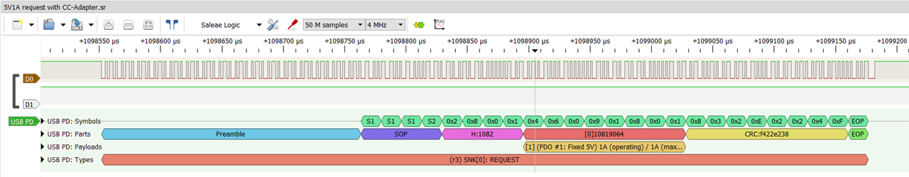
And because I really like the Pulseview/Sigrok PD decoder here is another image of a decoded packet showing the sink request for a fixed 5V/ 1A contract.

image

Now I have a nice tool to debug my attempt to design a USB-C PD source. As usual, I will write in more detail when I have a working design.


Useful links:
If anybody is interested, the board can be ordered at OSHpark. Did I mention that I find the afterdark option really useful and sexy.

shabaz's USB PD recent blog posts:
USB Type-C and Power Delivery: Any Interest?
100W USB Type-C Power Delivery Source: Getting Started

 baldengineer's post about opamp characteristics

  • Sign in to reply
  • wolfgangfriedrich
    wolfgangfriedrich over 2 years ago in reply to scottiebabe

    Thanks. I'll try to measure that and keep that in mind for the future.

    • Cancel
    • Vote Up 0 Vote Down
    • Sign in to reply
    • More
    • Cancel
  • scottiebabe
    scottiebabe over 2 years ago

    We all learn by experimenting! I believe device discovery occurs with vbus unpowered so the op-amps input esd diode may load the cc lines before vbus is applied. Likely not enough to cause a problem, but something to consider in the future. Happy probing! 

    • Cancel
    • Vote Up 0 Vote Down
    • Sign in to reply
    • More
    • Cancel
  • wolfgangfriedrich
    wolfgangfriedrich over 2 years ago in reply to shabaz

    Thanks, shabaz.

    The OSHpark option to make boards public is really neat. I was at the ordering end of this system as well. If it becomes hugely popular, I might set it up as a populated board for sale on Tindie. But I don't think so, the people doing low level USB-PD CC decoding is probably very narrow.

    • Cancel
    • Vote Up 0 Vote Down
    • Sign in to reply
    • More
    • Cancel
  • shabaz
    shabaz over 2 years ago

    Hi Wolfgang,

    Great work! Thanks for setting it up as a project where the boards can be ordered easily. This will be something I will try to construct at some point too, to learn about the messaging with PD chips.

    This color option looks really good!

    • Cancel
    • Vote Up 0 Vote Down
    • Sign in to reply
    • More
    • Cancel
  • wolfgangfriedrich
    wolfgangfriedrich over 2 years ago in reply to baldengineer

    Thanks James.

    Good grief, the D+/D- mix-up is definitely not intended. As you said, straight though, lucky me. Slight smile

    • Cancel
    • Vote Up 0 Vote Down
    • Sign in to reply
    • More
    • Cancel
>
element14 Community

element14 is the first online community specifically for engineers. Connect with your peers and get expert answers to your questions.

  • Members
  • Learn
  • Technologies
  • Challenges & Projects
  • Products
  • Store
  • About Us
  • Feedback & Support
  • FAQs
  • Terms of Use
  • Privacy Policy
  • Legal and Copyright Notices
  • Sitemap
  • Cookies

An Avnet Company © 2025 Premier Farnell Limited. All Rights Reserved.

Premier Farnell Ltd, registered in England and Wales (no 00876412), registered office: Farnell House, Forge Lane, Leeds LS12 2NE.

ICP 备案号 10220084.

Follow element14

  • X
  • Facebook
  • linkedin
  • YouTube