element14 Community
element14 Community
    Register Log In
  • Site
  • Search
  • Log In Register
  • Community Hub
    Community Hub
    • What's New on element14
    • Feedback and Support
    • Benefits of Membership
    • Personal Blogs
    • Members Area
    • Achievement Levels
  • Learn
    Learn
    • Ask an Expert
    • eBooks
    • element14 presents
    • Learning Center
    • Tech Spotlight
    • STEM Academy
    • Webinars, Training and Events
    • Learning Groups
  • Technologies
    Technologies
    • 3D Printing
    • FPGA
    • Industrial Automation
    • Internet of Things
    • Power & Energy
    • Sensors
    • Technology Groups
  • Challenges & Projects
    Challenges & Projects
    • Design Challenges
    • element14 presents Projects
    • Project14
    • Arduino Projects
    • Raspberry Pi Projects
    • Project Groups
  • Products
    Products
    • Arduino
    • Avnet & Tria Boards Community
    • Dev Tools
    • Manufacturers
    • Multicomp Pro
    • Product Groups
    • Raspberry Pi
    • RoadTests & Reviews
  • About Us
  • Store
    Store
    • Visit Your Store
    • Choose another store...
      • Europe
      •  Austria (German)
      •  Belgium (Dutch, French)
      •  Bulgaria (Bulgarian)
      •  Czech Republic (Czech)
      •  Denmark (Danish)
      •  Estonia (Estonian)
      •  Finland (Finnish)
      •  France (French)
      •  Germany (German)
      •  Hungary (Hungarian)
      •  Ireland
      •  Israel
      •  Italy (Italian)
      •  Latvia (Latvian)
      •  
      •  Lithuania (Lithuanian)
      •  Netherlands (Dutch)
      •  Norway (Norwegian)
      •  Poland (Polish)
      •  Portugal (Portuguese)
      •  Romania (Romanian)
      •  Russia (Russian)
      •  Slovakia (Slovak)
      •  Slovenia (Slovenian)
      •  Spain (Spanish)
      •  Sweden (Swedish)
      •  Switzerland(German, French)
      •  Turkey (Turkish)
      •  United Kingdom
      • Asia Pacific
      •  Australia
      •  China
      •  Hong Kong
      •  India
      •  Korea (Korean)
      •  Malaysia
      •  New Zealand
      •  Philippines
      •  Singapore
      •  Taiwan
      •  Thailand (Thai)
      • Americas
      •  Brazil (Portuguese)
      •  Canada
      •  Mexico (Spanish)
      •  United States
      Can't find the country/region you're looking for? Visit our export site or find a local distributor.
  • Translate
  • Profile
  • Settings
Power & Energy
  • Technologies
  • More
Power & Energy
Forum Smps sine wave
  • Blog
  • Forum
  • Quiz
  • Documents
  • Polls
  • Events
  • Mentions
  • Sub-Groups
  • Tags
  • More
  • Cancel
  • New
Actions
  • Share
  • More
  • Cancel
Forum Thread Details
  • State Suggested Answer
  • Replies 9 replies
  • Answers 5 answers
  • Subscribers 284 subscribers
  • Views 2208 views
  • Users 0 members are here
Related

Smps sine wave

bigsexy
bigsexy over 5 years ago

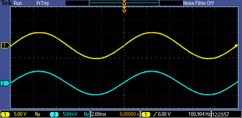
As I further learn about the intricacies of electronics and do not have an adequate oscilloscope I have a question regarding SMPS. I know how regular old go to hell transformers work and require a sine wave switching to positive and negative voltages to create the magnetic field induced into the iron core and so forth. But does a sine wave have to go Into negative voltages to work? Let me elaborate a little because I tend to over complicate my thoughts.
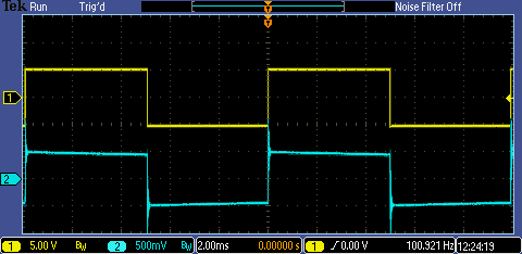
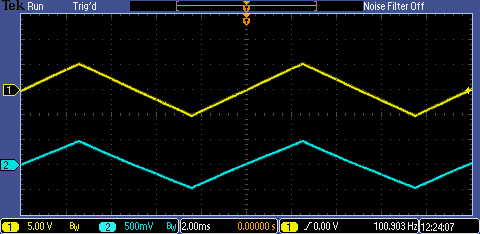
Lets say I have a mosfet that I use as a switch to pulse a dc voltage on and off at a significant speed in the kHz range through a wire wrapped in a coil on a transformer core, would that be able to create a half sine wave and therefore be used to induce a voltage in a secondary winding?

I am wondering if in a smps if the electronics recreate the sine wave to go high and low instead of high and off?

If this is confusing speak to you let me know and I will try to draw something up on paper and photo it for the thread.

  • Sign in to reply
  • Cancel

Top Replies

  • michaelkellett
    michaelkellett over 5 years ago +3 suggested
    It's too big a subject to explain in an answer here ! I had a quick Google for some tutorial type stuff and found this that isn't too bad: https://www.electronics-tutorials.ws/power/switch-mode-power-supply…
  • jc2048
    jc2048 over 5 years ago in reply to michaelkellett +3 suggested
    This is the best thing I've ever read on the subject, but I'm not sure it qualifies as an 'introduction' [someone reading it would need some familiarity with Faraday and Ampere and be capable of simple…
  • jc2048
    jc2048 over 5 years ago +3 suggested
    The waveform doesn't have to be a sinewave. If you'd like to see the effect of different waveforms, here's a selection from a pattern generator driving an old mains transformer that I found in one of my…
  • michaelkellett
    0 michaelkellett over 5 years ago

    It's too big a subject to explain in an answer here !


    I had a quick Google for some tutorial type stuff and found this that isn't too bad:


    https://www.electronics-tutorials.ws/power/switch-mode-power-supply.html


    There is a load of stuff on the web of course but very hard to follow and a lot is not helpful.


    Maybe some othe memebers can suggest their favorite introductions to the subject.


    MK

    • Cancel
    • Vote Up +3 Vote Down
    • Sign in to reply
    • Verify Answer
    • Reject Answer
    • Cancel
  • jw0752
    0 jw0752 over 5 years ago

    Hi Kevin,

    The simple answer to your question is that any time a current changes in a wire, whether it changes sinusoidally, linearly, or any other rate of change with respect to time the magnetic field that is generated also changes. A changing magnetic field will induce voltage in conductors that are present within the field. The sine wave is what is produced by a coil that is spinning in a constant magnetic field so we are familiar with this rate of change as that is how our house current is produced. The sine wave is not however necessary to produce induction in a transformer. Waves that are more square or triangular work also. Most SMPS make no attempt to produce a sine wave in the primary of their power supplies. the MOSFETs that turn the power on and off to the transformer are usually much closer to square waves than sine. SMPS usually deal with AC to DC or DC to DC conversion. A special type called an Inverter will convert from DC to AC and since the AC produced is usually for consumer use on appliances the better inverters will make an attempt at producing a sine wave output.

    John

    • Cancel
    • Vote Up +2 Vote Down
    • Sign in to reply
    • Verify Answer
    • Reject Answer
    • Cancel
  • fmilburn
    0 fmilburn over 5 years ago in reply to jw0752

    I cannot imagine a more succinct yet information filled paragraph than this :-)

    • Cancel
    • Vote Up +2 Vote Down
    • Sign in to reply
    • Verify Answer
    • Cancel
  • bigsexy
    0 bigsexy over 5 years ago

    So if I understand correctly, a transformer does not need the voltage to alternate between positive AND negative, and will work just from an electric field being pulsed on and off at a high rate?


    Also I want to add clarification to the last sentence of my original post. After re-reading it, it kind of comes off kind of a-hole’ish, what I meant to come across was I have a habit of making things very confusing and can try a different way if my question was confusing.


    And a big thank you for the answers! I also have another question I will have to start a new post as it is completely unrelated.

    • Cancel
    • Vote Up +2 Vote Down
    • Sign in to reply
    • Verify Answer
    • Cancel
  • jw0752
    0 jw0752 over 5 years ago in reply to bigsexy

    Hi Kevin,


    You are more or less correct. A voltage across a load ( I say across a load as this will produce a current) only needs to change in some way over time to create a changing magnetic field which can induce a current in another circuit. We need to be talking about magnetic fields and currents, not voltages and electric fields. A magnetic filed can only induce a current in another circuit when the field is changing or the other circuit is physically moving so as to cross the field lines of the magnetic field. As you would say the voltage (across a load) does not need to alternate between positive and negative, it only needs to change between one voltage and another voltage. Remember that until we plug a load into the wall outlet nothing happens. There is voltage there but for something to happen there must be a current.


    When you talk about plus and minus voltage you are choosing a reference point to be zero volts and measuring from there. Voltage is potential energy. Sometimes it is even called potential instead of voltage. We measure the voltage in our homes as 115 Volts rms but the actual voltage measured from the neutral wire designated as 0 volts to the hot wire goes from about +161V to -161V.  The peak to peak voltage in this case is 322 volts. We use the root mean square (rms) voltage as it tells us how much energy is actually available for a given load. It is kind of the average of the highs and lows. The rms voltage is equivalent to the DC voltage that would produce the same amount of work across a load of equal resistance.


    Your question was a good one and as Michael pointed out has a lot of depth which can be explored. If I have made any mistakes in what I have told you my friends on the forum will add corrections or clarifications. This is a great place to ask questions as everyone helps and participates just like a group of collaborative minds.


    John

    • Cancel
    • Vote Up +1 Vote Down
    • Sign in to reply
    • Verify Answer
    • Reject Answer
    • Cancel
  • jc2048
    0 jc2048 over 5 years ago in reply to michaelkellett

    This is the best thing I've ever read on the subject, but I'm not sure it qualifies as an 'introduction' [someone reading it would need some familiarity with Faraday and Ampere and be capable of simple maths].


    Magnetics Design Handbook by Lloyd H. Dixon, Jr


    https://www.ti.com/seclit/ml/slup132/slup132.pdf

    • Cancel
    • Vote Up +3 Vote Down
    • Sign in to reply
    • Verify Answer
    • Reject Answer
    • Cancel
  • jc2048
    0 jc2048 over 5 years ago

    The waveform doesn't have to be a sinewave. If you'd like to see the effect of different waveforms, here's a selection from a pattern generator driving an old mains transformer that I found in one of my junk boxes.


    image


    The primary is marked 240V and the secondary 12V 100mA (the secondary has a tap, so it's really 24V across both: ie a transformer ratio of 10:1). I'm driving it at approximately 100Hz.


    image

    image

    image

    image

    image


    The waveforms speak for themselves. Yellow trace is the input from the generator, blue trace is the output measured with a 10x probe with no other load.


    You can see from that that there's nothing particularly special about a sinewave. The transformer bandwidth is fairly limited with its laminated-steel core [probably below 100kHz], so sharp features of the waveforms will round off [not really noticeable at 100Hz], and you can see that the output winding 'rings' on very abrupt edges [that's resonance with capacitance from the winding and the probe], but other than that it transmits the waveform reasonably well.


    In the days of valve [vacuum tube] amplifiers, transformers were often used to match the output of the amplifier to the lower impedance of the loudspeaker.


    The last waveform isn't pure ac and would be very dodgy if it were your mains waveform [I should think it would run the core into saturation and cause damage]. I can get away with it with the generator because of all the resistance involved [the generator has a 50 Ohm in series with the output and the primary winding resistance is about 730 Ohms] and the much lower voltage, so there isn't the capability to get the current to the kind of levels that you would see cause problems.


    In the case of a switched winding, the reason you don't need to balance the waveform [time-integral of the voltage summing to zero over the cycle] is that if you let the winding go, the core corrects for itself by generating the opposing voltage. For that to happen, there needs to be a suitable path for the current to run and sufficient time. This is where it all starts to get complicated because there are many ways to drive windings and to effect the core 'reset', and also two fundamental ways to use a transformer in a switching circuit, forward and flyback, depending on whether the energy flows through or gets stored.

    • Cancel
    • Vote Up +3 Vote Down
    • Sign in to reply
    • Verify Answer
    • Reject Answer
    • Cancel
  • bigsexy
    0 bigsexy over 5 years ago

    A huge Thank You to everyone’s responses. I must say that you made it easy for me to understand. John your pics makes it easy for me particularly because I am more of a kinesthetic learner and very visual. Which is why I find programming difficult to grasp and more importantly to remember.


    The only reason I found this community is from Newark and making a few purchases from them before the website changed to Newark.com (I can’t seem to remember what it was a few years ago). But I am glad I did. I have posted a couple of questions on All About Circuits website before, but found some of the people way above my understanding and not exactly helpful. So props to the Element14 community!

    • Cancel
    • Vote Up +2 Vote Down
    • Sign in to reply
    • Verify Answer
    • Cancel
  • jw0752
    0 jw0752 over 5 years ago in reply to jc2048

    Hi Jon,


    I wanted to thank you again for posting the Magnetics Design Handbook. I have been printing a chapter or two at a time and reading them. I understand only to the skin depth of a high frequency current in a large gauge wire. The over all increase in my knowledge so far is that the physics of transformer and inductor design over different frequency ranges is way way way more complicated than I ever imagined. While this will probably never lead to me designing even a simple transformer it is very helpful to have an over view understanding of these devices.


    Thanks again for your contributions to the discussions on the forum. Your foundation based electronics is helping me and I suspect many others learn and fill in some of the empty spots in our knowledge.


    John

    • Cancel
    • Vote Up +2 Vote Down
    • Sign in to reply
    • Verify Answer
    • Cancel
element14 Community

element14 is the first online community specifically for engineers. Connect with your peers and get expert answers to your questions.

  • Members
  • Learn
  • Technologies
  • Challenges & Projects
  • Products
  • Store
  • About Us
  • Feedback & Support
  • FAQs
  • Terms of Use
  • Privacy Policy
  • Legal and Copyright Notices
  • Sitemap
  • Cookies

An Avnet Company © 2025 Premier Farnell Limited. All Rights Reserved.

Premier Farnell Ltd, registered in England and Wales (no 00876412), registered office: Farnell House, Forge Lane, Leeds LS12 2NE.

ICP 备案号 10220084.

Follow element14

  • X
  • Facebook
  • linkedin
  • YouTube