element14 Community
element14 Community
    Register Log In
  • Site
  • Search
  • Log In Register
  • About Us
  • Community Hub
    Community Hub
    • What's New on element14
    • Feedback and Support
    • Benefits of Membership
    • Personal Blogs
    • Members Area
    • Achievement Levels
  • Learn
    Learn
    • Ask an Expert
    • eBooks
    • element14 presents
    • Learning Center
    • Tech Spotlight
    • STEM Academy
    • Webinars, Training and Events
    • Learning Groups
  • Technologies
    Technologies
    • 3D Printing
    • FPGA
    • Industrial Automation
    • Internet of Things
    • Power & Energy
    • Sensors
    • Technology Groups
  • Challenges & Projects
    Challenges & Projects
    • Design Challenges
    • element14 presents Projects
    • Project14
    • Arduino Projects
    • Raspberry Pi Projects
    • Project Groups
  • Products
    Products
    • Arduino
    • Avnet Boards Community
    • Dev Tools
    • Manufacturers
    • Multicomp Pro
    • Product Groups
    • Raspberry Pi
    • RoadTests & Reviews
  • Store
    Store
    • Visit Your Store
    • Choose another store...
      • Europe
      •  Austria (German)
      •  Belgium (Dutch, French)
      •  Bulgaria (Bulgarian)
      •  Czech Republic (Czech)
      •  Denmark (Danish)
      •  Estonia (Estonian)
      •  Finland (Finnish)
      •  France (French)
      •  Germany (German)
      •  Hungary (Hungarian)
      •  Ireland
      •  Israel
      •  Italy (Italian)
      •  Latvia (Latvian)
      •  
      •  Lithuania (Lithuanian)
      •  Netherlands (Dutch)
      •  Norway (Norwegian)
      •  Poland (Polish)
      •  Portugal (Portuguese)
      •  Romania (Romanian)
      •  Russia (Russian)
      •  Slovakia (Slovak)
      •  Slovenia (Slovenian)
      •  Spain (Spanish)
      •  Sweden (Swedish)
      •  Switzerland(German, French)
      •  Turkey (Turkish)
      •  United Kingdom
      • Asia Pacific
      •  Australia
      •  China
      •  Hong Kong
      •  India
      •  Korea (Korean)
      •  Malaysia
      •  New Zealand
      •  Philippines
      •  Singapore
      •  Taiwan
      •  Thailand (Thai)
      • Americas
      •  Brazil (Portuguese)
      •  Canada
      •  Mexico (Spanish)
      •  United States
      Can't find the country/region you're looking for? Visit our export site or find a local distributor.
  • Translate
  • Profile
  • Settings
Power & Energy
  • Technologies
  • More
Power & Energy
Forum Visual Signs of Capacitor Failure - Bulging
  • Blog
  • Forum
  • Quiz
  • Documents
  • Polls
  • Events
  • Mentions
  • Sub-Groups
  • Tags
  • More
  • Cancel
  • New
Actions
  • Share
  • More
  • Cancel
Forum Thread Details
  • Replies 28 replies
  • Subscribers 285 subscribers
  • Views 5519 views
  • Users 0 members are here
Related

Visual Signs of Capacitor Failure - Bulging

Jan Cumps
Jan Cumps over 1 year ago

I received a new TV box from the cable provider They suggested to drop the old one at an electronics recycle collector. That didn't happen Slight smile - I opened it up. I've put the internal hard drive for sale on a 2nd hand site. For the other components, I'm checking what (if anything) is worth keeping.

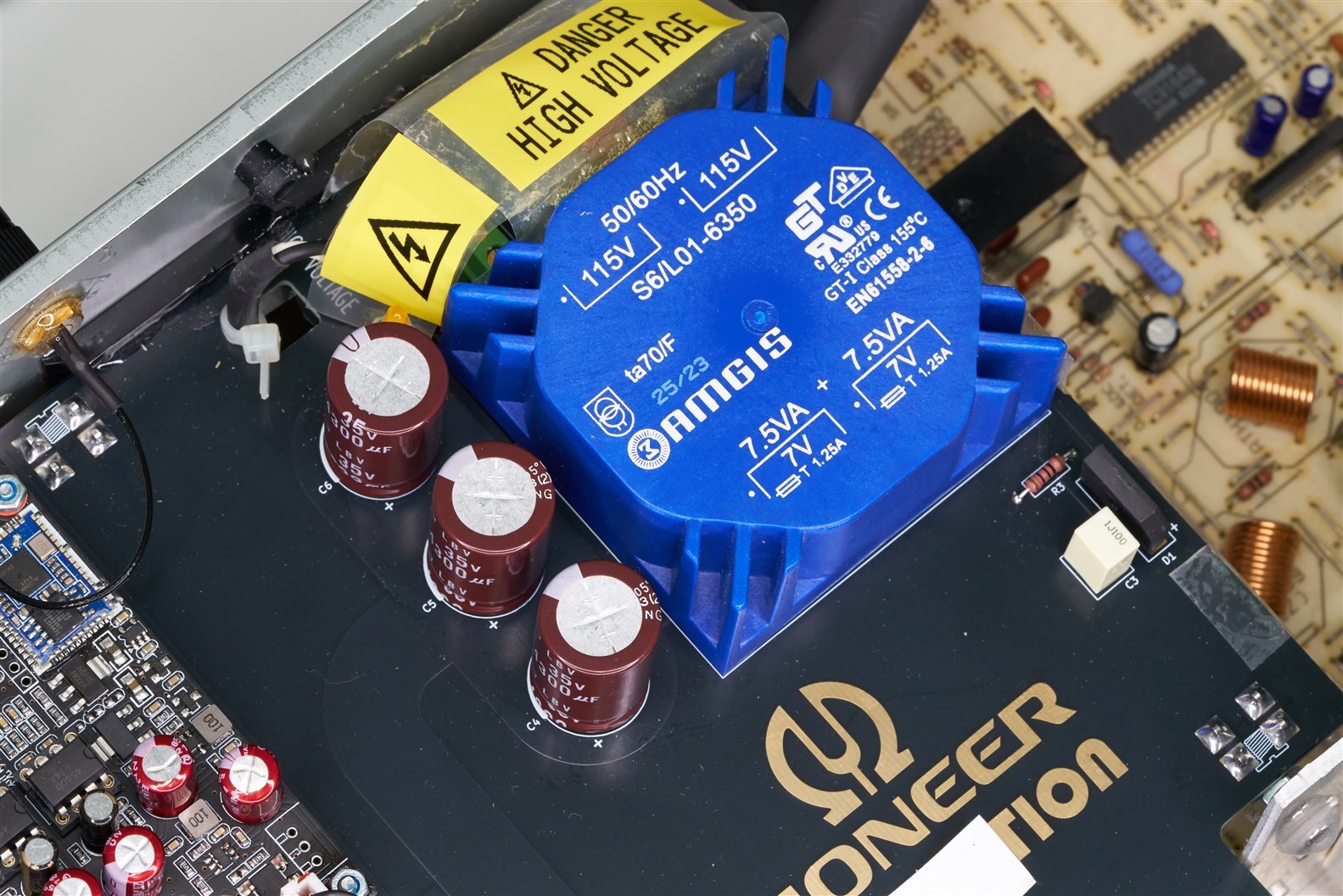
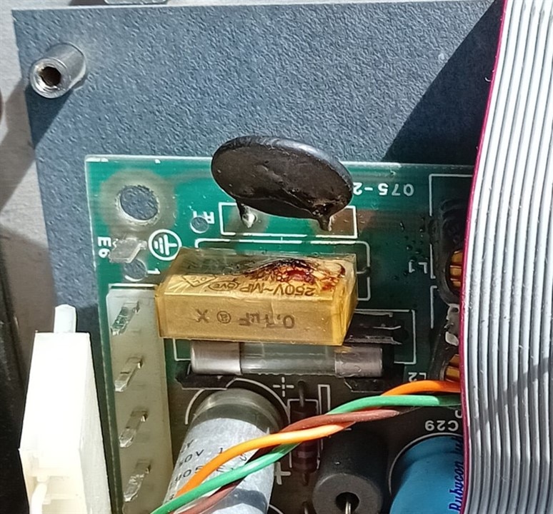
What caught the attention, is that one of the electrolytical caps is beyond end-of-life. It's definitely bulging: It's the first time that I see one where the symptom is so obvious. I had others that failed or leaked. But never such a visible sign of the internal pressure effects.

image

Can you spot the culprit?

Title inspiration: capacitor labs.

  • Sign in to reply
  • Cancel

Top Replies

  • dougw
    dougw over 1 year ago +4
    The top isn't flat anymore....
  • beacon_dave
    beacon_dave over 1 year ago +3
    Jan Cumps said: It's definitely bulging: It's the first time that I see one where the symptom is so obvious. I had others that failed or leaked. But never such a visible sign of the internal pressure effects…
  • michaelkellett
    michaelkellett over 1 year ago in reply to shabaz +3
    If you want low noise then put some little ceramic caps around the rectifier. Doing so is mentioned in AOE Edition 3 (maybe in the X pages book) and after I read that I measured a design I was working…
  • michaelkellett
    michaelkellett over 1 year ago in reply to shabaz

    If you want low noise then put some little ceramic caps around the rectifier. Doing so is mentioned in AOE Edition 3 (maybe in the X pages book) and after I read that I measured a design I was working on. I was seeing horrible 25V amplitude HF ringing around the rectifier but the little caps (470nF) from input of rectifier to ground can fix it. Worth experimenting because caps with series resistors can be better.

    Second thing, on light or zero load the max output from your transformer will be 14V * 1.1 (transformer regulation) * 1.1(mains high) * 1.1 (engineering tolerance !) = 26.4V pk. Your main caps are OK but ideally you should use a 50V cap if it has any tantalum in it (that rule (rated cap voltage = 2 * max voltage applied) comes from solid tantalum but I apply it to power caps with any tantalum).

    I'm using tantalum poly's in power supplies so I hope its OK Relaxed

    MK

    • Cancel
    • Vote Up +3 Vote Down
    • Sign in to reply
    • Cancel
  • shabaz
    shabaz over 1 year ago in reply to michaelkellett

    Hi Michael,

    Thanks for the info! I took a look at AoE3, page 634 mentions a damping network, I have footprints for that on the PCB so I'll be sure to add those and will check out the X-chapters in case they mention further.The full schematic is shown below (I have no access to an earth connection due to this being a retrofit inside a double-insulated product). Thanks for the cap feedback, I've searched online, and found a 50V tant poly cap which is the same size, so I'll use that instead. The PCB arrives this week, so hopefully I'll have some feedback how it goes soon!

    Also, just noticed that section of AoE reminds of the need for a 1M resistor across the line filter input.. I'll order a suitable resistor while I'm at it, and solder that in too.

    image

    • Cancel
    • Vote Up 0 Vote Down
    • Sign in to reply
    • Cancel
  • michaelkellett
    michaelkellett over 1 year ago in reply to shabaz

    I'll be interested to hear how well it works and how noisy.

    I've just done a design with one of AD/Linear Technology  "SilentSwitcher" chips (not built any yet) so would be interesting to compare.

    MK

    • Cancel
    • Vote Up +2 Vote Down
    • Sign in to reply
    • Cancel
  • shabaz
    shabaz over 1 year ago in reply to michaelkellett

    Also, unrelated, there's some quite nice transformers on AliExpress (I cannot find them at normal distributors), the primary-to-secondary capacitance was measured to be just under 100 pF, i.e. about a third compared to a similarly-sized toroid because there's concentric bobbins with the inner bobbins containing one winding, and the outer containing the other, so there's quite a gap, and also has a shield between the concentric bobbins, that needs to be earthed. I've not tried this transformer yet. (I'm not using this transformer for the circuit mentioned, that will be a normal toroid). 

    image

    image

    • Cancel
    • Vote Up +1 Vote Down
    • Sign in to reply
    • Cancel
  • shabaz
    shabaz over 1 year ago in reply to michaelkellett

    Unfortunately I've not had a chance to do any measurements : ( I was planning on using the MCC 172 to see power supply noise up to 25 kHz or so that it supports, but I've needed to finish this project quickly, and didn't have time to set this test up in an enclosure before fitting it in the end equipment (an audio amp/radio receiver).The PSU is simply used to power an off-the-shelf Bluetooth audio module (to try to make this product suitable for modern times! It is 30 years old).

    The LM1086 layout was pretty much as described in the datasheet, and I used a 50V tant poly on the input (it is that black cap labelled C11).

    image

    The transformer and associated circuitry is below. The cap+resistor damping is next to the bridge rectifier.

    What I'm not sure about, is the covering over the high voltage bits. It's not required for insulation purposes, but I still wanted a finger guard in case anyone opens the enclosure.

    I've used UL94V-2 mylar (and impact glue), which I think is OK because it's not touching anything that could arc, and is thin enough that there's only a finite amount of burning it could possibly ever do, even if it were possible to ignite it. But I'm unsure. I'd like to obtain better material for such purposes, but would like to leave the current material in if it's acceptable.

    image

    Audio quality is finally good/acceptable! I originally prototyped with a Meanwell AC-DC module, but there was mains hum : ( (presumably because of the high transformer capacitance between windings).

    I found some neat items for helping retro-fit this board. One is a chunky  M4 right-angle mount   originally intended for screw-fitted antennas, but I've mounted it on the underside, with four large heavily soldered through-hole pads, and epoxy-glue to secure it further.

    The other item was a horizontal card guide.

    I needed to drill zero holes to retrofit it all. All holes were created using this hole punch kit. It's excellent, has quite a lot of clearance, and easy to be precise because each punch has a protruding centre-point. Plus, the punches/dies are available as low-cost spares if they wear out. 

    Also swapped out the (awful, and slightly corroded) UHF connector (Belling-Lee) for the FM antenna, and replaced with 75 ohm BNC. I'm replacing with a custom antenna which is simply a standard T-shaped antenna, but with a 75:300 ohm transformer. It might be no good for AM! But I'm hoping AM is of little interest to the user.

    • Cancel
    • Vote Up +2 Vote Down
    • Sign in to reply
    • Cancel
  • shabaz
    shabaz over 1 year ago in reply to shabaz

    Antenna assembly, it is basically 75-ohm coax on the left (RG179) going to a BNC plug, and the 300-ohm antenna balanced line (feeder) on the right. The transformer is MABA-011039 and it is soldered to a scrap of board where the copper was cut into four quadrants.

    image

    • Cancel
    • Vote Up +2 Vote Down
    • Sign in to reply
    • Cancel
  • geralds
    geralds over 1 year ago
    Jan Cumps said:

    Yes. I have seen these low-budget caps many times.

    Such caps were terrible in a project with our customer.
    We had built a communication device with route recording for the ÖBB (Austrian Federal Railway).
    The power supply of this device had an electrolytic capacitor built in that was sensitive to temperature.
    How? What? ----- Well, in the higher regions the ambient temperature can quickly drop very low even in summer.
    One day the customer came with such a defective device.
    I tested it, but at first I couldn't find any fault. - At room temperature in the workshop.
    Then I took a cold spray or a hot soldering iron tip and looked for components to see if they were temperature sensitive.
    Voila, one of these electrolytic capacitors clicked when it cooled down. Its capacity was suddenly only half or it was causing a short circuit.
    I then had to drive across the country and replace these electrolytic capacitors.
    There were about 100s of devices.

    Oh yes... with a capacitor like this it can be quite annoying because you can't see this kind of error from the outside.

    • Cancel
    • Vote Up +1 Vote Down
    • Sign in to reply
    • Cancel
  • michaelkellett
    michaelkellett over 1 year ago in reply to geralds

    It's not just low budget caps - time, temperature, volts and ripple current all take their toll.

    This is a pic of the motherboard from an HP59401A (HPIB/GPIB Bus System Analyzer), 1980 - 1990 or so - approx 40 years old.

    image

    After the cap blew out the owner just left to poor thing to rot in its own juice for some years. I cleaned it up and replaced the cap (temporarily) with a decent (£0.5 part).

    image

    But the two diodes beside it and some track had suffered badly.  I cleaned it up as best as I could without complete disassembly and replaced the diodes on the other side of the board.

    image

    The -12V supply is restored.

    But the 59401A still doesn't work, so no point in replacing all the electrolytics with really good ones (£30 or more for the ones on the motherboard), much. much more if I did the solid tantalums as well.

    The problem is that the instrument is two big boards of 74 and 74S series TTL , most obsolete and very expensive to replace. So do I want to spend 100 hours or so on restoring it, or just build a new one using a modern micro and display with much more memory and other nice features ?

    I do want a GPIB analyzer to help use/fix other ancient HP instruments.

    Still thinking about it - but mainly thinking about the new design !

    MK

    • Cancel
    • Vote Up +3 Vote Down
    • Sign in to reply
    • Cancel
  • Jan Cumps
    Jan Cumps over 1 year ago in reply to michaelkellett

    If you 'd go the modern way, this kit would still be a good source for some decent voltage references.

    • Cancel
    • Vote Up 0 Vote Down
    • Sign in to reply
    • Cancel
  • beacon_dave
    beacon_dave over 1 year ago in reply to michaelkellett

    Eaton 2075 noise-gain analyzer. Similar vintage... similar problems.

    imageimage

    Stuff just doesn't last these days... Slight smile

    • Cancel
    • Vote Up 0 Vote Down
    • Sign in to reply
    • Cancel
<>
element14 Community

element14 is the first online community specifically for engineers. Connect with your peers and get expert answers to your questions.

  • Members
  • Learn
  • Technologies
  • Challenges & Projects
  • Products
  • Store
  • About Us
  • Feedback & Support
  • FAQs
  • Terms of Use
  • Privacy Policy
  • Legal and Copyright Notices
  • Sitemap
  • Cookies

An Avnet Company © 2025 Premier Farnell Limited. All Rights Reserved.

Premier Farnell Ltd, registered in England and Wales (no 00876412), registered office: Farnell House, Forge Lane, Leeds LS12 2NE.

ICP 备案号 10220084.

Follow element14

  • X
  • Facebook
  • linkedin
  • YouTube