element14 Community
element14 Community
    Register Log In
  • Site
  • Search
  • Log In Register
  • Community Hub
    Community Hub
    • What's New on element14
    • Feedback and Support
    • Benefits of Membership
    • Personal Blogs
    • Members Area
    • Achievement Levels
  • Learn
    Learn
    • Ask an Expert
    • eBooks
    • element14 presents
    • Learning Center
    • Tech Spotlight
    • STEM Academy
    • Webinars, Training and Events
    • Learning Groups
  • Technologies
    Technologies
    • 3D Printing
    • FPGA
    • Industrial Automation
    • Internet of Things
    • Power & Energy
    • Sensors
    • Technology Groups
  • Challenges & Projects
    Challenges & Projects
    • Design Challenges
    • element14 presents Projects
    • Project14
    • Arduino Projects
    • Raspberry Pi Projects
    • Project Groups
  • Products & Partners
    Products & Partners
    • Arduino
    • Avnet & Tria Boards Community
    • Dev Tools
    • Manufacturers
    • Multicomp Pro
    • Product Groups
    • Raspberry Pi
    • RoadTests & Reviews
  • About Us
    About the element14 Community
  • Store
    Store
    • Visit Your Store
    • Choose another store...
      • Europe
      •  Austria (German)
      •  Belgium (Dutch, French)
      •  Bulgaria (Bulgarian)
      •  Czech Republic (Czech)
      •  Denmark (Danish)
      •  Estonia (Estonian)
      •  Finland (Finnish)
      •  France (French)
      •  Germany (German)
      •  Hungary (Hungarian)
      •  Ireland
      •  Israel
      •  Italy (Italian)
      •  Latvia (Latvian)
      •  
      •  Lithuania (Lithuanian)
      •  Netherlands (Dutch)
      •  Norway (Norwegian)
      •  Poland (Polish)
      •  Portugal (Portuguese)
      •  Romania (Romanian)
      •  Russia (Russian)
      •  Slovakia (Slovak)
      •  Slovenia (Slovenian)
      •  Spain (Spanish)
      •  Sweden (Swedish)
      •  Switzerland(German, French)
      •  Turkey (Turkish)
      •  United Kingdom
      • Asia Pacific
      •  Australia
      •  China
      •  Hong Kong
      •  India
      •  Japan
      •  Korea (Korean)
      •  Malaysia
      •  New Zealand
      •  Philippines
      •  Singapore
      •  Taiwan
      •  Thailand (Thai)
      •  Vietnam
      • Americas
      •  Brazil (Portuguese)
      •  Canada
      •  Mexico (Spanish)
      •  United States
      Can't find the country/region you're looking for? Visit our export site or find a local distributor.
  • Translate
  • Profile
  • Settings
Sensors
  • Technologies
  • More
Sensors
Blog Audio-Technica U841A Microphone Teardown
  • Blog
  • Forum
  • Documents
  • Quiz
  • Events
  • Polls
  • Members
  • Mentions
  • Sub-Groups
  • Tags
  • More
  • Cancel
  • New
Join Sensors to participate - click to join for free!
  • Share
  • More
  • Cancel
Group Actions
  • Group RSS
  • More
  • Cancel
Engagement
  • Author Author: shabaz
  • Date Created: 23 Sep 2026 11:39 PM Date Created
  • Views 346 views
  • Likes 10 likes
  • Comments 17 comments
  • speech
  • reverse-engineering
  • microphone
  • audio
  • U841A
  • electret
  • condenser
  • conferencing
  • audio-technica
  • teardown
Related
Recommended

Audio-Technica U841A Microphone Teardown

shabaz
shabaz
23 Sep 2026


It’s not everyday I take apart a (reasonably pricey) microphone! But, I was curious, and taking things apart is sometimes how one learns.

A long time ago I took apart an Echo Dot, which contains very different microphone technology (MEMS devices, seven-fold), so check that out too if it's of interest.

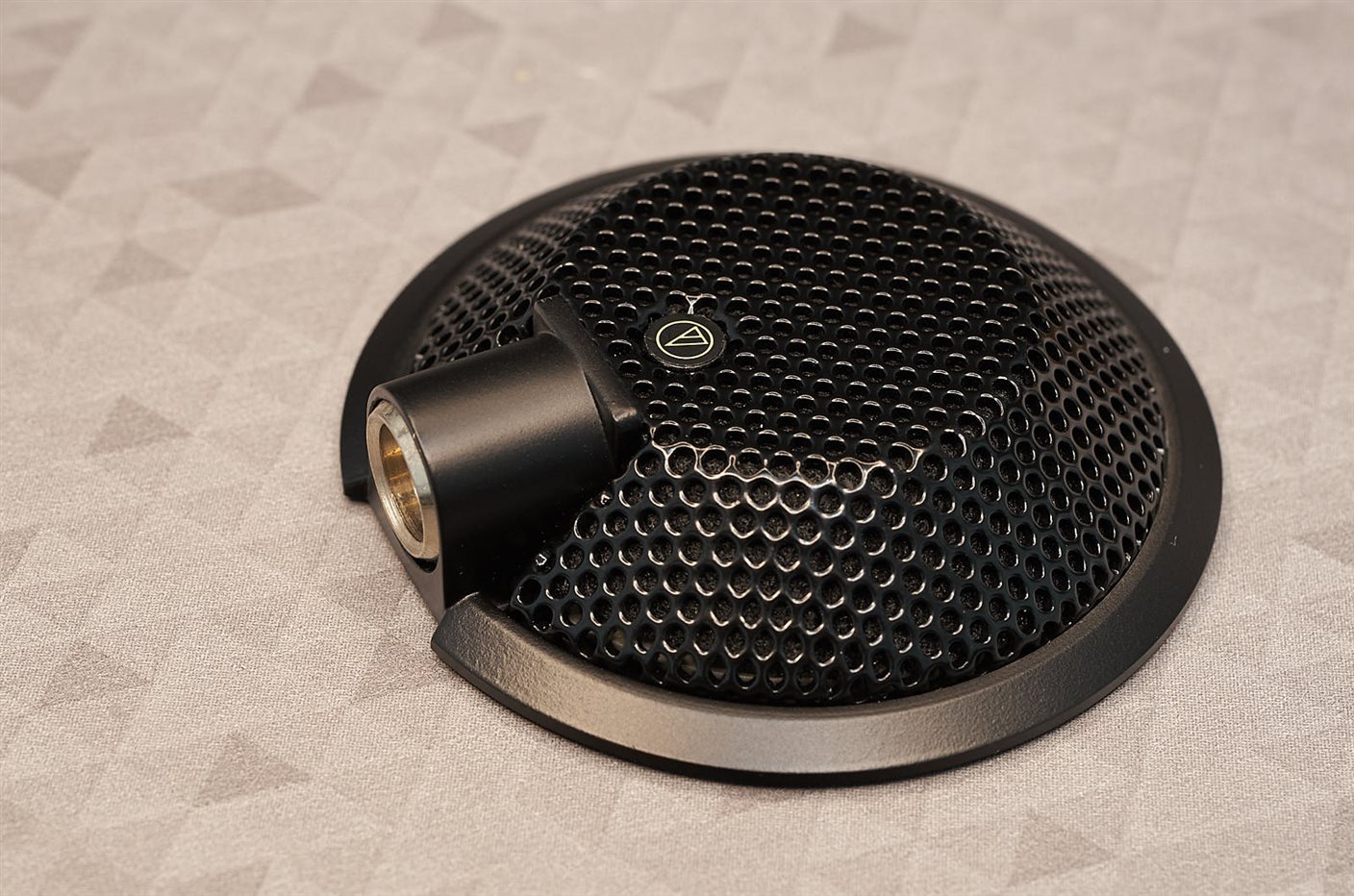
Anyway, the U841A is an electret condenser mic, intended for (I believe) speech for audio/videoconferencing purposes. Hopefully any audio experts can provide more detail.


The microphone is very ruggedly built. The secret to opening it up, is to peel off that tiny circular logo on the top; it reveals a screw : ) Then the stamped metal grille lifts off.
image

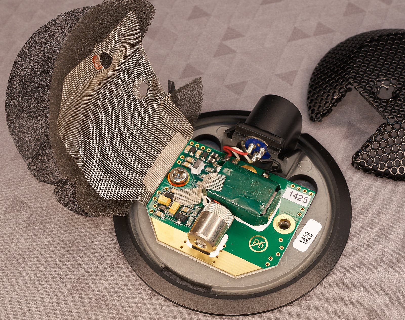
There’s a lot to visually unpack just from the photo below. On the left, you’ll see three material layers; a thin (0.2 mm) stiff layer (kind of like collar lining! there must be a technical name for it..), followed by 2 mm thick soft acoustic foam, followed by (what feels like) nickel mesh 0.25 mm thick (very slightly magnetic), which is secured to the ground, and must be acting as electrical shielding.

The big green rectangle was originally a mystery, although I suspected it may be a transformer. Everything is superbly constructed.
image

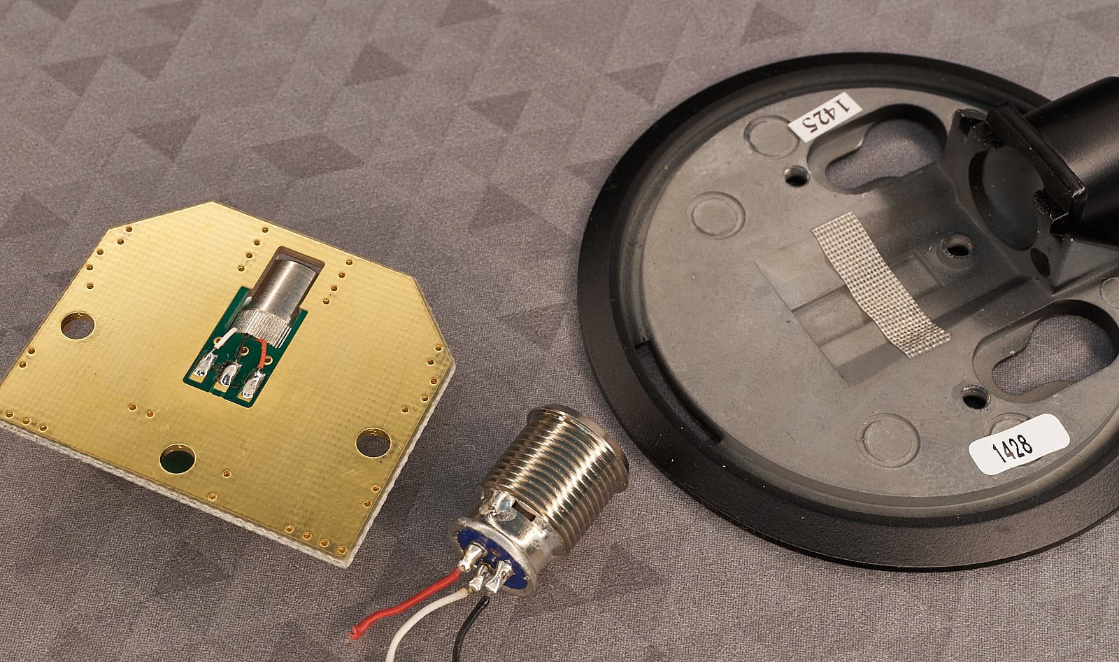
Pulling it apart further (there’s a grub screw which holds the mini XLR connector in place, and it needs to be desoldered to remove the PCB. You can see the electret element has three wires, which suggests it contains an internal amplifier.
image

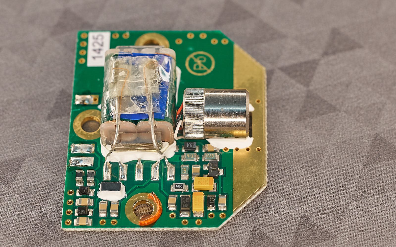
Here’s a closeup of the circuit board, with the green tape removed; now it’s clear that was hiding a transformer.

In the photo below, the board area can be split into three portions; the lower-left contains circuitry for filtering off RF interference arriving via the microphone cable, the center houses the transformer for constructing a balanced output, and the lower-right contains the audio amplifier. 
image

I tried reverse-engineering the circuit (without destroying it, hence I’m sure I have some of this wrong – and all of the non-polarized capacitor values are placeholder guesses).

image

I’m not sure what D1 is, it has a DA inscription. With some thought, the black component inscribed DA must be a capacitor. Edit: now measured out-of-circuit, it is a 100 nF capacitor.

D5/6/7 are guesses (they have a 561 inscription (Edit: see comments below, D6/7 are most likely 56V zener diodes), they may be 5.6V Zener diodes (although I was under the impression this mic supported a far higher phantom voltage input, so either I am mistaken about the part, or this mic may be a slightly different variant). Edit: D5 is possibly 5.6V zener. 

I can’t say I really understand what’s going on with the transformer input and please don’t assume I drew the circuit layout correctly. If you have suggestions/corrections, please let me know. I do intend to fire it up and feed in a signal in place of the mic element and take some measurements one day, but finding time is hard. Funnily enough, I've been thinking about constructing a microphone simulator (but for digital mics).

Any help would be appreciated. Thanks for reading!

  • Sign in to reply
Parents
  • jc2048
    jc2048 19 days ago

    Interesting tear-down. The transformer construction is fascinating. Would the core material just be steel, like a mains transformer, or something more exotic?

    I'd say D6 and D7 were 56V zeners. The marking is somewhat different to D5 (if they'd come from the same reel on the pick-and-place machine, you'd think they would be the same).

    It's very likely this microphone will run from a 48V phantom supply.

    Note that, if you try it on a mixer, you may not actually see the full 48V with the mic connected. Inside the mixer, pins 2 and 3 of the XLR are commonly fed via resistors from the 48V (if you have it enabled), so it will sit down from the 48 on load - probably somewhere around the 40V mark with it taking 2mA.

    The DA shape looks wrong for a cap and there's an NXP BSX384-C11 11V zener with DA marking in that style of package. But how that fits with the circuit you've drawn, I've got no idea.

    You've just reminded me that a while back I bought a couple of I2S MEMs microphones to experiment with. Must get and do that now the weather is more amenable.

    • Cancel
    • Vote Up 0 Vote Down
    • Sign in to reply
    • More
    • Cancel
  • michaelkellett
    michaelkellett 19 days ago in reply to jc2048

     jc2048 said: 

    It's very likely this microphone will run from a 48V phantom supply.

    I think you are correct there - I'd missed D2 which looks like a 2mA constant current diode.

    A LONG time ago when I worked at Lustraphone (approx 1974) we used mu metal laminations for microphone transformers - high permeability for high inductance but very low saturation -  fine for a microphone. Or ir might be amorphous iron which came along  a lot later but I don't know if its good for microphones.

    MK

    • Cancel
    • Vote Up 0 Vote Down
    • Sign in to reply
    • More
    • Cancel
Comment
  • michaelkellett
    michaelkellett 19 days ago in reply to jc2048

     jc2048 said: 

    It's very likely this microphone will run from a 48V phantom supply.

    I think you are correct there - I'd missed D2 which looks like a 2mA constant current diode.

    A LONG time ago when I worked at Lustraphone (approx 1974) we used mu metal laminations for microphone transformers - high permeability for high inductance but very low saturation -  fine for a microphone. Or ir might be amorphous iron which came along  a lot later but I don't know if its good for microphones.

    MK

    • Cancel
    • Vote Up 0 Vote Down
    • Sign in to reply
    • More
    • Cancel
Children
  • shabaz
    shabaz 18 days ago in reply to michaelkellett

    Interesting, the science museum has a mention of Lustraphone Lustraphone | Science Museum Group Collection

    Next time I'm there I'll see if they have those items that are in their collection on display.

    The transformer is tiny, the core dimensions are 19 x 8 mm rectangle, of 2.8 mm thickness for the laminations, yet inductance was quite high (about 3.4H at 1 kHz with 10 mV drive). The inter-winding capacitance is low (about 145pF from memory, I measured it a couple of days ago), so possibly the windings are on separate bobbins, although it doesn't look like it from the way the wires are coming out from the tape, so I'm not sure at all.

    image

    • Cancel
    • Vote Up 0 Vote Down
    • Sign in to reply
    • More
    • Cancel
element14 Community

element14 is the first online community specifically for engineers. Connect with your peers and get expert answers to your questions.

  • Members
  • Learn
  • Technologies
  • Challenges & Projects
  • Products
  • Store
  • About Us
  • Feedback & Support
  • FAQs
  • Terms of Use
  • Privacy Policy
  • Legal and Copyright Notices
  • Sitemap
  • Cookies

An Avnet Company © 2026 Premier Farnell Limited. All Rights Reserved.

Premier Farnell Ltd, registered in England and Wales (no 00876412), registered office: Farnell House, Forge Lane, Leeds LS12 2NE.

Follow element14

  • X
  • Facebook
  • linkedin
  • YouTube