


Table of Contents
Introduction
Time-of-Flight sensors are fascinating. They measure the time it takes for light to travel to a target and bounce back. With an array of such sensing elements, it becomes possible to obtain a three-dimensional impression of the environment, and ‘see’ how far things are, and the directions they are moving in.
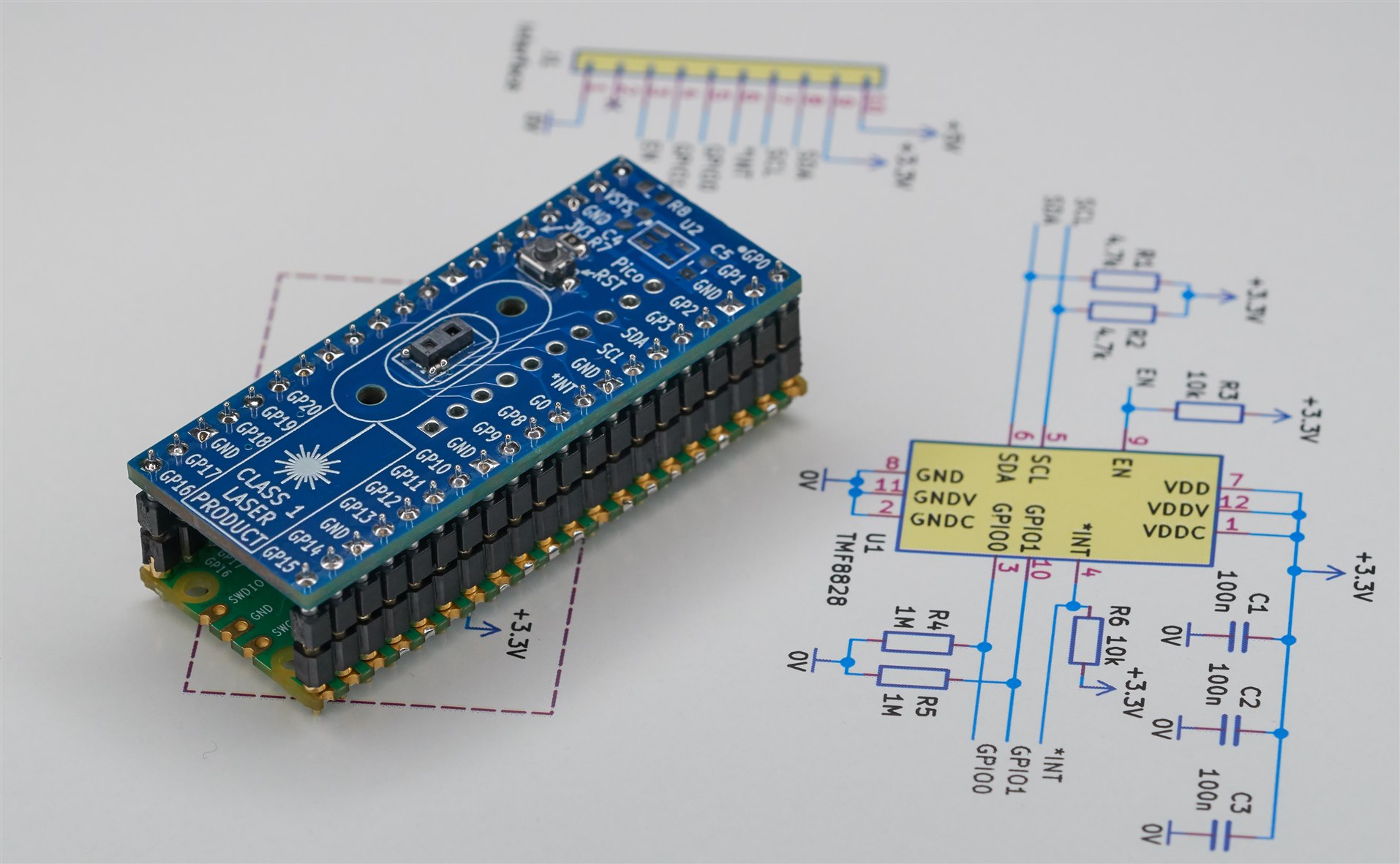
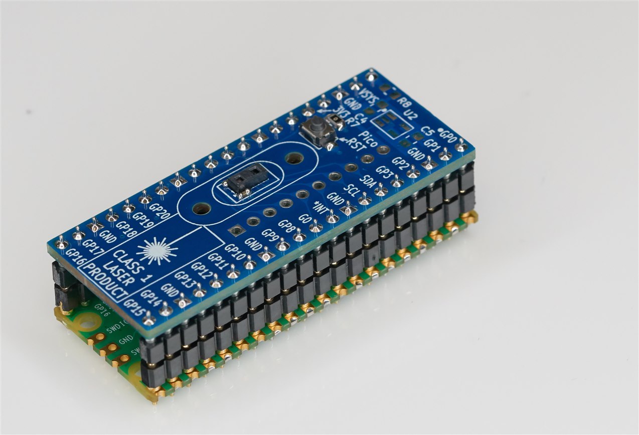
This blog post (inspired by an article from CorinnaR. - Engineer-to-engineer: understanding time-of-flight sensing ) is about a tiny (grain of rice sized) device from ams/Osram which contains both a camera-like grid of optical sensors, and a laser! It is called the TMF8828. It’s that tiny two-aperture device visible in the photo below, soldered to a board which is piggy-backed onto a Pi Pico.
The device fires a wide spread of light (using its tiny laser and built-in lens) and then the grid of optical sensors measure the time it takes for that light to reflect back from a target (or multiple targets in the area!).
You could use it for occupancy or person or object movement sensing, distance measurement to a reflective surface, or to perform gesture sensing by examining which sensors in the grid are triggered and in what sequence. You could make interesting theremin-style musical instruments.
In this blog post, the hardware is discussed (you could self-assemble the board as I did, or purchase an alternative board from the manufacturer, which is functionally compatible but uses an Arduino). I then pass the measurements to the PC over a USB UART connection, so that they can be observed graphically using software, or captured using Python code.
See the following three-minute video summary:
Quick Overview
In short, a TMF8828 board is needed. You could either assemble a DIY board as I did, or purchase a different one. There are a few development boards available for the TMF8828, they cost about £50 ($60 USD), although there could be slightly lower-cost options in the future (Adafruit has one listed as “coming soon”).
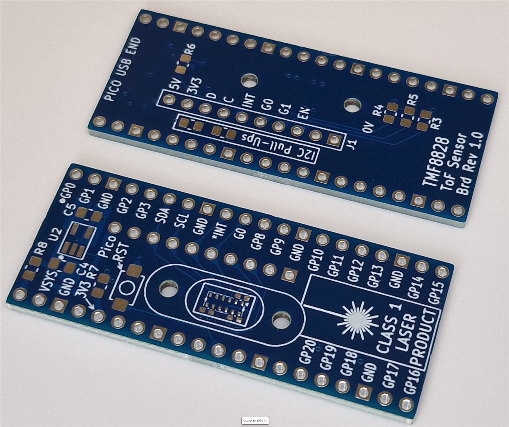
I decided to build my own development board and the PCB files are published. The main difference between my board and the other ones, is that mine will directly attach to a Pi Pico board if desired. If that’s not what is required, then it could still be wired to any other microcontroller of course. See the GitHub page for all files and code.
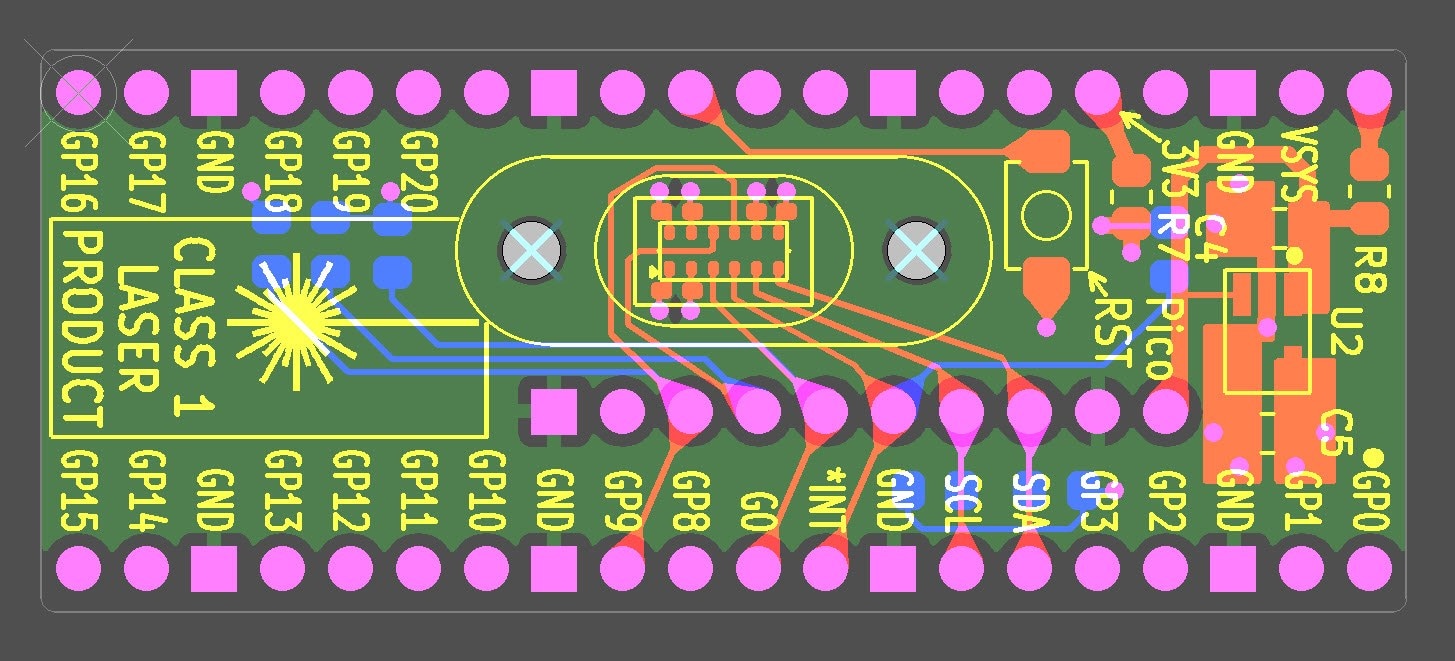
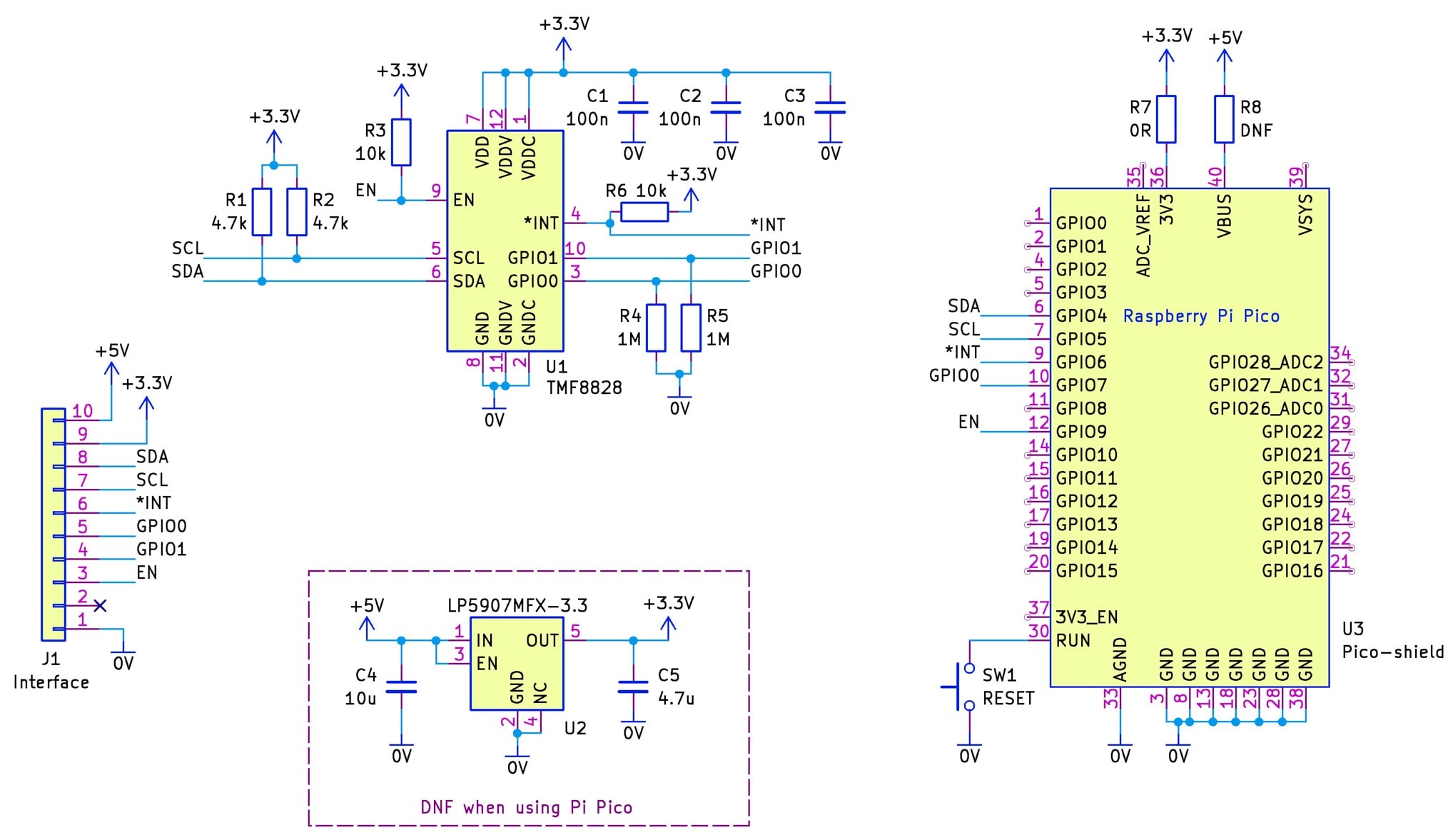
The board interfaces using I2C (and a couple of GPIO pins used for enabling the device and for device interrupts), and requires a 3.3V supply. The board has space for an optional 5V to 3.3V regulator, but that’s not needed when using it with a Pi Pico. The circuit diagram is straightforward, shown below.
If you wish to replicate this project, it will cost about £15 ($20) for the parts, and perhaps $2 for the PCB to be manufactured.
After that, the board is connected to a microcontroller (in my case a Pi Pico as mentioned above).
Then, set the Pi Pico into a bootloader mode (see the video below to see how to do that and transfer the firmware to it. After that, the firmware will start to automatically run.
Now you can install and run ready-made software called TMF882x EvalSW Arduino Demo GUI (available from the Software section on the ams OSRAM TMF8828 Eval Board Product Page). on your PC (Note: If you're using a Pi Pico instead of an Arduino, then you’ll need to make a small change to a config file that will be installed in your C:\Users\username\AppData\Roaming\ams-OSRAM AG folder, called TMF8828 ARDUINO DEMO.ini – edit the line beginning with COM_PORT_DESCRIPTION so that it says COM_PORT_DESCRIPTION=USB Serial Device).
The software will automatically connect to the Pi Pico, and display in real-time an animated grid showing the measurements. There’s also a 3D view that can be enabled in the software, which shows an isometric view with the distance on the vertical axis.
How Does it Work?
As mentioned, the TMF8828 contains a tiny laser, covered with a frosted lens. It provides a small flood of light, pulsed at over 17 million times a second (confirmed by using a light sensor. Click here to see how: Fast Response Light Sensing with Photodiodes: Building a DIY Radiometer! ).
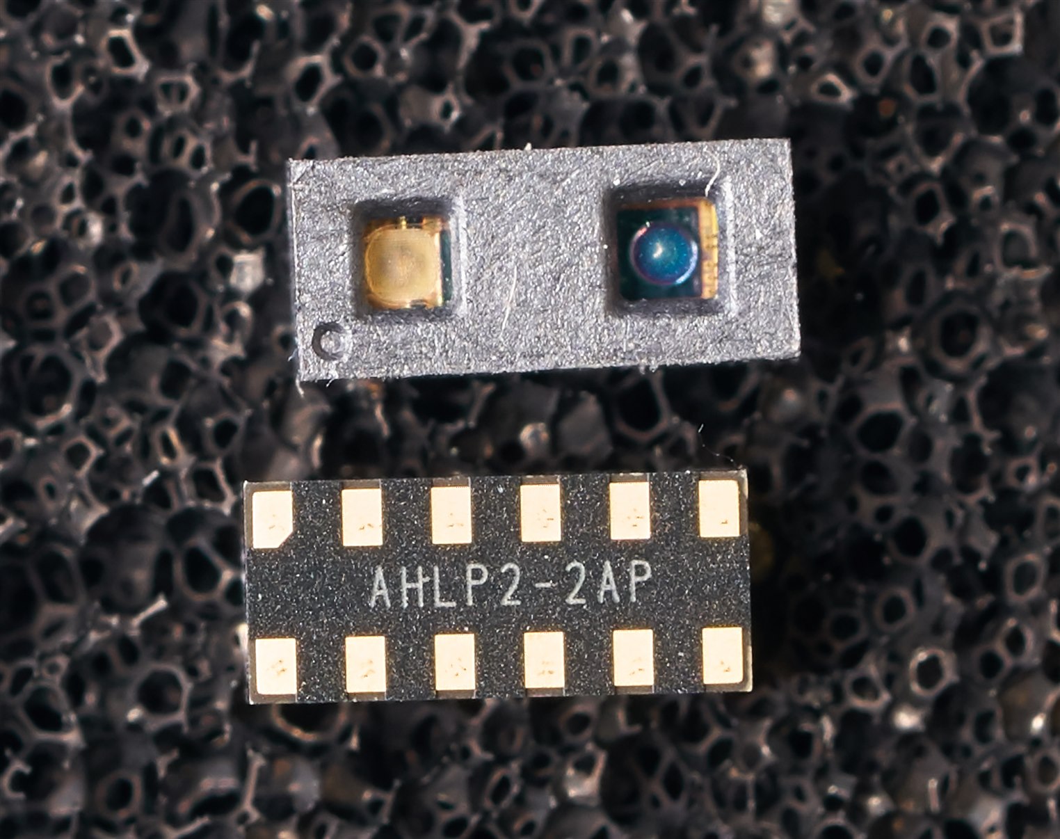
Reflected light enters another aperture on the TMF8828, and is focussed onto an array of Single Photon Avalanche Diodes (SPAD). These are like a silicon equivalent of a photomultiplier tube; when a photon hits a SPAD, there is a likelihood that it will cause a large detectable amount of current to flow. The TMF8828 measures how long it takes from the moment the laser is pulsed, to the moment when each SPAD detects it. There is actually some crosstalk from the laser to the array of SPADs, so actually it measures from the moment the crosstalk is detected by the SPADs, until the reflected photons arrive. The way SPADs work, they need to be reset after each successful photon detection, so the TMF8828 internally rapidly resets the SPAD after the crosstalk event, and after a reflected photon arrives.
Since there’s a chance that a single photon might be missed and a subsequent photon might be detected, the TMF8828 will reset the SPAD repeatedly, hundreds of thousands of times, and re-fires the laser each time, so that a more accurate time measurement can be made by using stats (i.e. by binning the results and looking for the bin with the largest amount) along with a confidence level percentage. By default, the binning occurs for 550 thousand laser pulses.
There are about 180 SPADs behind the lens, and only some of them are used, grouped in areas or ‘zones’. In the case of the TMF8828, there are six SPADs per output pixel (known as a zone in ams/Osram terminology. The TMF8828 captures a spread-out 4x4 array of these zones (i.e. 16 zones), and then repeats three more times for different slightly shifted SPAD groupings, to achieve a total of 64 zones (i.e. 8x8 array combined).
The diagram below (taken and slightly edited from ams/Osram documentation) shows the 64 zones, each has a number. The different colors represent the four 4x4 sub-captures, each of which contains 16 zones, and they are meshed to produce the final 64 zones result. The diagram can be used as a reference for performing the meshing.
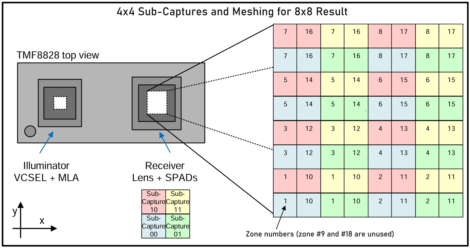
An interesting thing to note is that because multiple SPADs are behind each zone, and results are binned, it becomes possible to detect more than one object in a zone. For instance, there may be a smaller object at a closer distance, and a larger object further back, both detectable in the field of view of a zone. The TMF8828 can actually report back the distances for up to two objects! It will report the nearest object distance first.
All of the above is fairly complex to co-ordinate, so the TMF8828 happens to contain a pre-programmed microcontroller internally, with an I2C slave interface, so that any external host microcontroller doesn’t need to do as much.
I2C Registers Overview
Reading and Writing Registers
The TMF8828 supports registers for reading and writing. The registers are addressed with a single byte.
Usage is simple. You can read or write registers individually, or sequentially.
To write a register (or registers) just perform an I2C write operation with the first byte being the register address, and all subsequent bytes will be written to that register address onward.
To read a register (or registers) you simply need to do an I2C write containing the register address. Then, when you perform an I2C read operation, the TMF8828 will provide the contents from that address onward. An I2C ‘repeated start’ is optional between the register address and the read operation.
Application Mode Pages
The register addresses can serve multiple purposes, because the registers are paged in.
The TMF8828 runs in two modes; the normal mode is application mode, and the other mode is bootload mode.
In the table below, anything shaded black is accessible in all pages (all application mode pages and the bootload mode page). Anything shaded gray is available in all pages too, apart from when in a bootload mode. You can tell if the bootload mode is in progress, if register 0x00 (APPID) contains 0x80. If it contains 0x03 (which is the only other option supported) then you’re in the normal application mode.
I’ll focus on some of the key application mode pages. There is far too much detail, so I’ve summarized things into the following register map diagrams, and for the detail, you’ll need to dig into the datasheet.
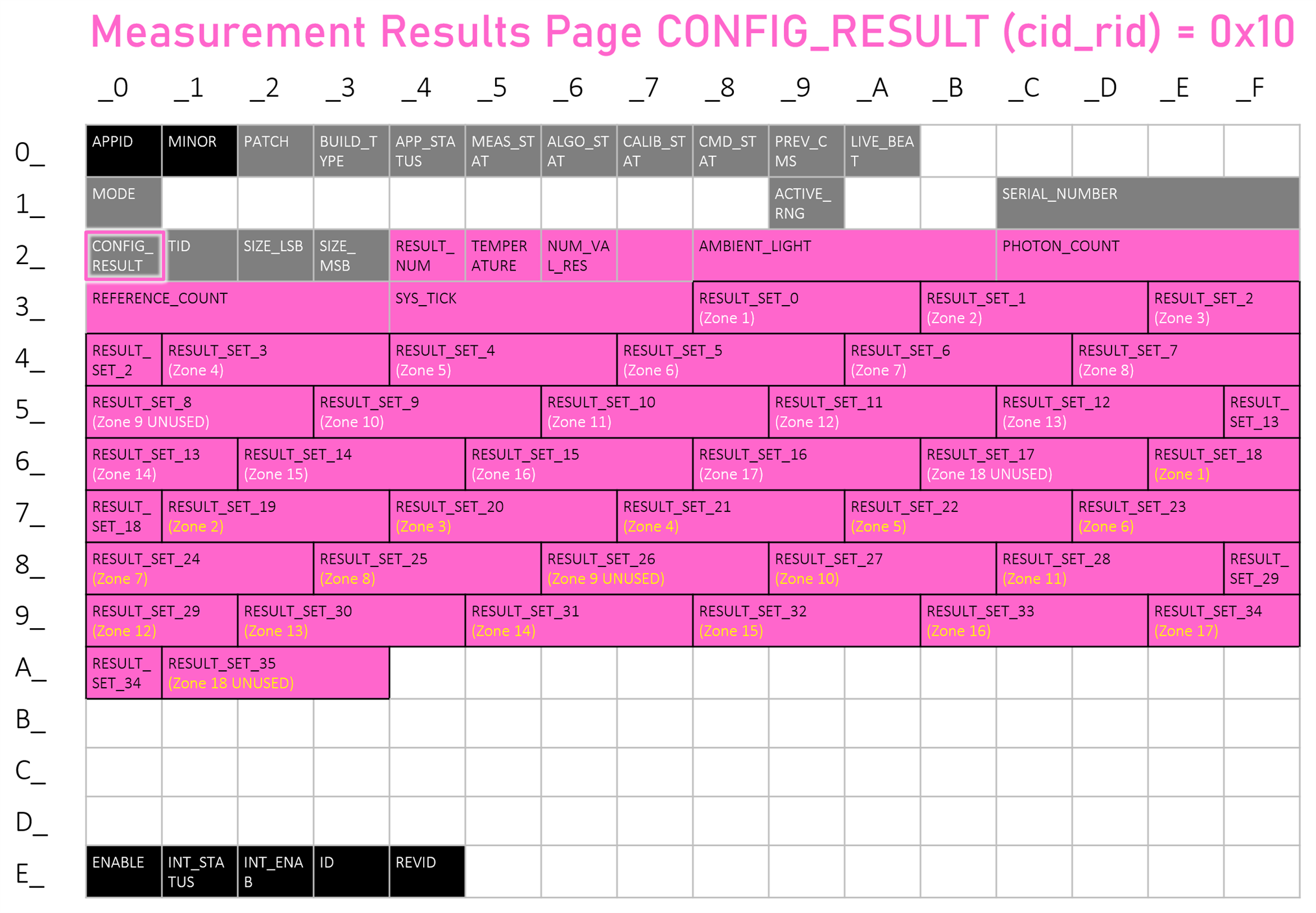
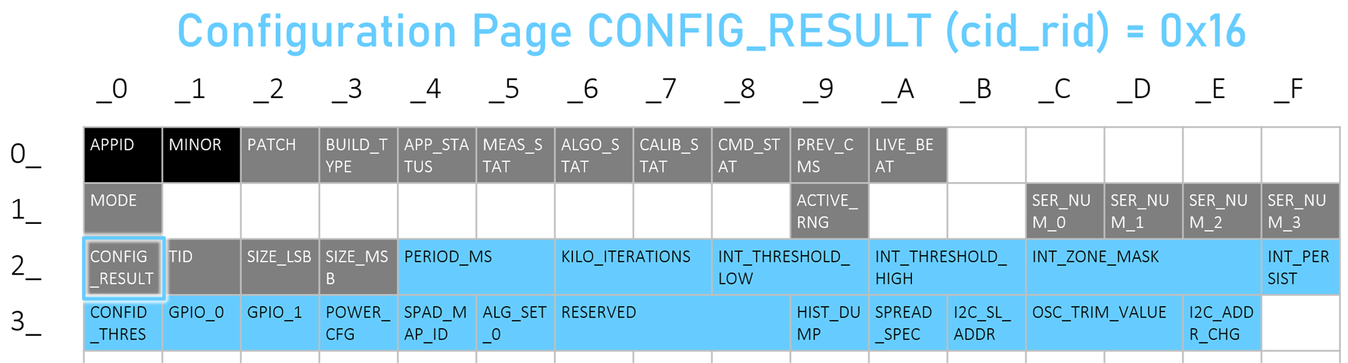
The pinkish-magenta shaded content below shows the most important page, which is the measurement results page. You’ll know if the page is set to measurement results, because the register 0x20 (CONFIG_RESULT also known as cid_rid) will contain the value 0x10.
If you look at the pink-magenta content, you’ll see most of it contains 36 groups of three bytes (i.e. 24 bits). Those three bytes contain the confidence value (8 bits) and the remainder 16 bits contains the measured distance.
As described earlier, each 8x8 result is really composed of four 4x4 sub-captures that mesh together (see the earlier diagram). The measurement results page is read four times, to obtain all four sub-captures. The four sub-captures are enumerated 0-3, and that is encoded in the two least significant bytes of the RESULT_NUMBER register (0x24).
It was mentioned earlier that the TMF8828 can detect up to two objects, a near one and a far one, within each zone, since there are multiple SPADs per zone, and sometimes an object behind a nearby object may be within the field of view per zone. In the diagram below, the measurements for nearby objects are shown in white. The values in yellow are for optional further objects whenever more than one object is detected.
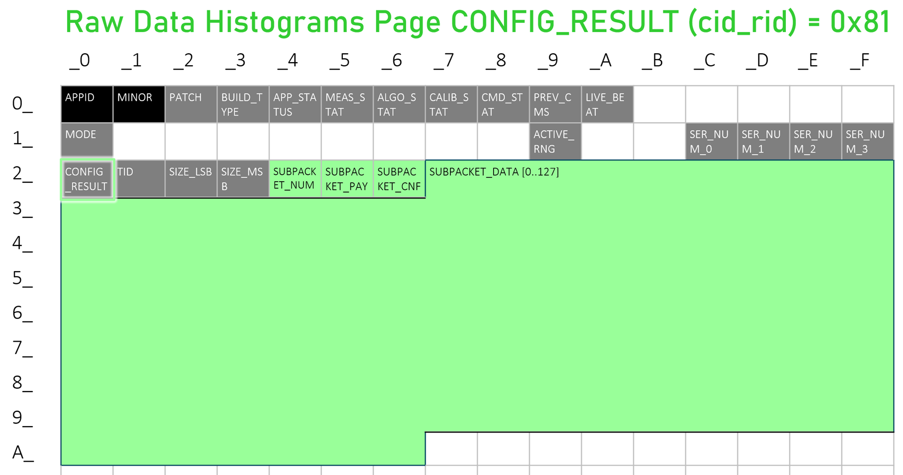
If the CONFIG_RESULT register contains a value of 0x81, then you’re in the Raw Data Histograms page. I have not explored this page yet.
The configuration page can be used to set the number of laser pulses that are used to perform the measurements.
USB UART Interface
The Pi Pico exposes a USB UART interface. I copied the manufacturer’s Arduino code (I stripped off all Arduino requirements, so that the code can be built for any microcontroller in theory) so that the interface is compatible with the PC software available on the ams OSRAM website. It is possible to explore it using serial console terminal software. Alternatively, check out the Python demo code.
The key thing to note is that when data is being streamed to the PC, it is in the following format:
#Obj,A,R,T,N,S, followed 72 values and then a newline character.
A = I2C address, usually 65
R = result number, of which the two least significant bits indicate the sub-capture
T = temperature in degrees C
N = number of valid results
S = sysTick value (a timestamp)
The next 72 values are actually 36 pairs of zone measurement results, where the first in each pair is the distance in millimetres, and the second in each pair is the confidence value (higher is better) for the measurement. See the earlier Measurement Results Page diagram, to see the zone numbering, and the earlier diagram which shows how to mesh four sets of those results into an 8x8 array.
Here is an example output line as sent to the PC.
#Obj,65,185,33,24,61353057,653,48,643,35,660,77,647,22,32,140,693,80,648,26,675,61,0,0,666,46,652,36,704,80,645,24,620,98,694,43,615,38,698,43,0,0,0,0,0,0,0,0,827,51,1133,59,1039,52,0,0,954,34,0,0,0,0,0,0,0,0,1186,17,1064,16,1090,50,0,0,995,31,0,0
Browser Based App
I decided to use the Web Serial API, to create a simple browser-based application. The advantage of this is that it should be feasible to connect the Pi Pico to a mobile phone or tablet, and not just a PC. This could be useful when trying out the device in different locations, where it could get awkward to bring a larger desktop or laptop. I have not tested with mobile for now. The Web Serial API works with Chrome on desktop machines, but is only supported on certain browsers on some phones. See the earlier video to see the web app in action.
Summary
The TMF8828 is an interesting device. It’s not the easiest part to work with, due to the optical nature of it, since it will ideally require a transparent cover window. It is also down to the developer to code any useful algorithms to utilise the array of measurements. It has a lot of potential however, for those willing to put the time in to explore it further. Hopefully the information in this blog post can partially help with that.
This blog post covered how to connect the TMF8828 to a microcontroller, and how to capture or view measurements using Python and JavaScript applications on the PC. This will be useful for learning how to best make use of the data, before coding a standalone microcontroller application.
For standalone applications, the microcontroller source code on GitHub can be easily modified to not use the USB UART, and pass the data to your own code. GitHub link: https://github.com/shabaz123/TMF8828
Thanks for reading!
Top Comments
-

genebren
-
Cancel
-
Vote Up
0
Vote Down
-
-
Sign in to reply
-
More
-
Cancel
-

shabaz
in reply to genebren
-
Cancel
-
Vote Up
0
Vote Down
-
-
Sign in to reply
-
More
-
Cancel
-

genebren
in reply to shabaz
-
Cancel
-
Vote Up
0
Vote Down
-
-
Sign in to reply
-
More
-
Cancel
Comment-

genebren
in reply to shabaz
-
Cancel
-
Vote Up
0
Vote Down
-
-
Sign in to reply
-
More
-
Cancel
Children