element14 Community
element14 Community
    Register Log In
  • Site
  • Search
  • Log In Register
  • Community Hub
    Community Hub
    • What's New on element14
    • Feedback and Support
    • Benefits of Membership
    • Personal Blogs
    • Members Area
    • Achievement Levels
  • Learn
    Learn
    • Ask an Expert
    • eBooks
    • element14 presents
    • Learning Center
    • Tech Spotlight
    • STEM Academy
    • Webinars, Training and Events
    • Learning Groups
  • Technologies
    Technologies
    • 3D Printing
    • FPGA
    • Industrial Automation
    • Internet of Things
    • Power & Energy
    • Sensors
    • Technology Groups
  • Challenges & Projects
    Challenges & Projects
    • Design Challenges
    • element14 presents Projects
    • Project14
    • Arduino Projects
    • Raspberry Pi Projects
    • Project Groups
  • Products
    Products
    • Arduino
    • Avnet & Tria Boards Community
    • Dev Tools
    • Manufacturers
    • Multicomp Pro
    • Product Groups
    • Raspberry Pi
    • RoadTests & Reviews
  • About Us
    About the element14 Community
  • Store
    Store
    • Visit Your Store
    • Choose another store...
      • Europe
      •  Austria (German)
      •  Belgium (Dutch, French)
      •  Bulgaria (Bulgarian)
      •  Czech Republic (Czech)
      •  Denmark (Danish)
      •  Estonia (Estonian)
      •  Finland (Finnish)
      •  France (French)
      •  Germany (German)
      •  Hungary (Hungarian)
      •  Ireland
      •  Israel
      •  Italy (Italian)
      •  Latvia (Latvian)
      •  
      •  Lithuania (Lithuanian)
      •  Netherlands (Dutch)
      •  Norway (Norwegian)
      •  Poland (Polish)
      •  Portugal (Portuguese)
      •  Romania (Romanian)
      •  Russia (Russian)
      •  Slovakia (Slovak)
      •  Slovenia (Slovenian)
      •  Spain (Spanish)
      •  Sweden (Swedish)
      •  Switzerland(German, French)
      •  Turkey (Turkish)
      •  United Kingdom
      • Asia Pacific
      •  Australia
      •  China
      •  Hong Kong
      •  India
      •  Japan
      •  Korea (Korean)
      •  Malaysia
      •  New Zealand
      •  Philippines
      •  Singapore
      •  Taiwan
      •  Thailand (Thai)
      •  Vietnam
      • Americas
      •  Brazil (Portuguese)
      •  Canada
      •  Mexico (Spanish)
      •  United States
      Can't find the country/region you're looking for? Visit our export site or find a local distributor.
  • Translate
  • Profile
  • Settings
Test & Tools
  • Technologies
  • More
Test & Tools
Blog Electronic DC Load - Design and Build to test PSU Project
  • Blog
  • Forum
  • Documents
  • Files
  • Members
  • Mentions
  • Sub-Groups
  • Tags
  • More
  • Cancel
  • New
Join Test & Tools to participate - click to join for free!
  • Share
  • More
  • Cancel
Group Actions
  • Group RSS
  • More
  • Cancel
Engagement
  • Author Author: Robert Peter Oakes
  • Date Created: 2 Jun 2015 5:14 AM Date Created
  • Views 12060 views
  • Likes 7 likes
  • Comments 32 comments
  • modular_power_supply
  • electronic_dc_load
  • energy_power
  • dc_load
Related
Recommended

Electronic DC Load - Design and Build to test PSU Project

Robert Peter Oakes
Robert Peter Oakes
2 Jun 2015

Back tot he Main Modular Bench power System Project The Modular Bench Power Supply ++, The Essential DIY Build for Every EE Student and Old Timer alike...


I keep promising myself I will build an Electronic DC Load and have kept defering it, well no longer, I finally ot it designed and tested on a breadboard and will be following up with a completed unit in a project case


It can go way above 30V (60 to be precice and upto 5Amps), the MOSFET I used the IRFP064 is able to go to 70Amps but thats more than my wiring would stand and way more than i need so I designed the load to go upto 5Amps for now. All I need to do though is change the current sense resistor and it can easily become a 10Amp unit


For the heatsink I tested with a standard one but subsiquently found an old CPU heatsing with a Fan attached which looks like it will do a grand job of cooling the MOSFET etc so it will be the one I use in the build.


Testin showed I can load as little as 250mV and still control upto an Amp which is great and once im over 1V source voltage I can go all the way to 5Amps with ease.


Now you all know the math "Power = Volts * Amps) so therefor will know that at 30V an 5Amps theres 150W being dissipated in the MOSFET and thats a lot of heat. I am pretty sure the CPU heatsing even with the fan will still get pretty hot and I look forward to characturizing it once the bukd is done. till then I have no idea how well it will work but I am sure it will be better than the one I tested the circuit with


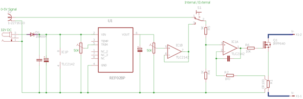
for now, here is the schamitic I came up with
image


It will use between 12 and 24V for the DC in, has a REF02 Voltage reference to provide the manual setting via a 10 Turn pot and has a trimmer to accuratly set the top output to precisly 5A if so desired.

I also included a BNC input as an alternate control allowing a signal generator to control the load enabling many more test scenarious to be executed like transient response testing, noise response, Waveform based profile, pulse response etc.


The design does have a frequency limit before the output falls off of only a few hundred Hertz but that should be more than enough for this. It may be way better once it is off the bread board and the wiring is significanly shorter too but I wont be able to test that till the buld is complete. I will add a video to this blog once that is done and tested


anyway, enough banter, here is the video (Yes Im back to my 1+ hour videos... sorry I tried)

You don't have permission to edit metadata of this video.
Edit media
x
image
Upload Preview
image


Hope you enjoy


Thanks to Vishay Precision Group ( VPG) Bulk Metal Film division for their kind donation of the current sense resistors and precision metal film resistors used in the resistor divider part of the design. It takes the use of this project to the next level by bringing stability to the key parts of the design in the order of a few parts per million... oh yaaaa.

  • Sign in to reply

Top Comments

  • jw0752
    jw0752 over 10 years ago in reply to e14 Contributor +3
    Hi Monica, Su Englais esta bien, mejor que mi Espanol. Don't worry too much about R-1. You can build one that will be accurate enough for this application. Just get a regular 0.1 ohm resistor and tie extra…
  • Robert Peter Oakes
    Robert Peter Oakes over 9 years ago in reply to stephanc +3
    I just checked on the first one ( IRL540N) and it is not even showing a DC spec, nothing more than a 10mS pulse This is the safe operating area.
  • Robert Peter Oakes
    Robert Peter Oakes over 10 years ago in reply to jw0752 +2
    Perfect jw0752 , that is exactly what I would have done if Vishay had not been so generous with some samples and is a perfect example of how to roll your own when the needs arise Thanks for sharing
Parents
  • michaelkellett
    michaelkellett over 11 years ago

    @Peter, I may have missed it somewhere but I'm not sure what transient response you are aiming for with your power supply. Decent commercial supplies offer 50uS transient response times (I checked Keysight and Rigol)  - so if your load is to be able to test to this sort of spec you need a 5uS response time  -  I can't quite understand why you are aiming as low as " only a few hundred Hertz".

    If you reduce R6, possibly use a faster op amp and tune the compensation capacitor I can't see why you shouldn't get a much better response.


    For transient tests I'm more likely to use a power resistor switched by a MOSFET which is either on or off - less flexible but (almost) 100% stable !


    For steady state stuff I have an computer controlled electronic load but it was a lot pricier than your home brew.


    MK

    • Cancel
    • Vote Up +1 Vote Down
    • Sign in to reply
    • More
    • Cancel
  • Robert Peter Oakes
    Robert Peter Oakes over 11 years ago in reply to michaelkellett

    Hi Mike


    You make some very good points, I think some of the limits may be imposed by having long wires and it being on a bread board but either way I like the idea of shooting for the 50 uSec range so I will perform some tuning


    It is easy to hook the MOSFET directly to the AWG so will see its native response time fist to see where the issue is coming from. ALso the 10K on the Gate will slow thinks down due to Gate Capacitance etc so I will reduce that down a bit at a time to also "Tune it"


    Looks like another 1Hr Video in the Works image... Ill blame you this time lol.


    Thanks


    Peter

    • Cancel
    • Vote Up +1 Vote Down
    • Sign in to reply
    • More
    • Cancel
  • mcb1
    mcb1 over 11 years ago in reply to Robert Peter Oakes

    Looks like another 1Hr Video

    Should be only a few microseconds given what you're looking at ..image

    • Cancel
    • Vote Up 0 Vote Down
    • Sign in to reply
    • More
    • Cancel
Comment
  • mcb1
    mcb1 over 11 years ago in reply to Robert Peter Oakes

    Looks like another 1Hr Video

    Should be only a few microseconds given what you're looking at ..image

    • Cancel
    • Vote Up 0 Vote Down
    • Sign in to reply
    • More
    • Cancel
Children
  • Robert Peter Oakes
    Robert Peter Oakes over 11 years ago in reply to mcb1

    Yes, my power supply circuits are inspired by older HP Power supplies but the DC Load was not. The Source PSU I was testing though was a Keithley 2200 series and its specifications are

    <150 ms to within 75 mV following a change from 0.1 A to 1 A

    I was banging this from 0 - 5A and it looked like it was keeping up well within its specifications so I am wondering if the DC Load is actually OK and it was the Keithley that was the issue. I will have to get a good capacity battery and try that instead

    • Cancel
    • Vote Up 0 Vote Down
    • Sign in to reply
    • More
    • Cancel
  • michaelkellett
    michaelkellett over 11 years ago in reply to Robert Peter Oakes

    Another possibility (other than battery) is to shunt the supply with a big low ESR capacitor (or bank of same) and pulse the load. If you put a resistor in series with the supply the supply dynamics are removed from the results.

    For example, 20V, 10R series resistor 10,000 uF, 4R load, on time 500uS, off time 50mS, average current = 50mA. The voltage on the capacitor will drop by about 0.25V during the pulse and the difference in minimum to peak current from the supply will be about 25mA. The average supply current will be about 50mA.


    The capacitor ESR should be less than 0.1R otherwise the 5A current pulses will drop too many volts.


    MK

    • Cancel
    • Vote Up 0 Vote Down
    • Sign in to reply
    • More
    • Cancel
  • Robert Peter Oakes
    Robert Peter Oakes over 11 years ago in reply to michaelkellett

    So did some playing with decoupling in the signal patchs and now have it way way better, I will be recording an update this weekend


    how does under 100uS sound on the breadboard no less image, I have a feeling that what is left is actually caused by the breadboard itself (Ringing etc) and longer than leads then the final build will have


    Peter

    • Cancel
    • Vote Up +1 Vote Down
    • Sign in to reply
    • More
    • Cancel
  • michaelkellett
    michaelkellett over 11 years ago in reply to Robert Peter Oakes

    Sounds much better - I've blogged elsewhere about attempts to drive a big MOSFET as a load switch which you might find interesting:


    Its in analog design group as Power Supply Dynamic Load testing.


    I might add a bit to it today.


    MK

    • Cancel
    • Vote Up 0 Vote Down
    • Sign in to reply
    • More
    • Cancel
  • Robert Peter Oakes
    Robert Peter Oakes over 11 years ago in reply to michaelkellett

    Just had a look, it is interesting and very much like my previous temporary load setups but I used them in the linear region, not as switches.


    my current design is very different in my objectives as I want to be able to select any current from mA through to Amps using a POT, a Wave Gen or later a DAC from micro-controller


    I have an op-amp in order to conrol the current across a sense resistor, the current is based on a linear applied voltage 0-5V input representing currently 0-5A, this does introduce some phase shift from input to drive though due to the op amp and FET / negative feedback


    Im using the MOSFET as the load resistor so I can set the current to be any value i wish based on the sense resistor value chosen, not as a switch with a load resistor therefor its working in its linear region


    the mosfet I am using is very fast and is targeted at switching regulators etc for its marketed use


    you are getting impressibe results but this is not with a design that gives me the flexable range I desire and depends on the passive load resistor


    On the positive side, you feedback did encourage me to play a little more to get the results I now have, even with a pretty basic circuit.


    Peter

    • Cancel
    • Vote Up +1 Vote Down
    • Sign in to reply
    • More
    • Cancel
element14 Community

element14 is the first online community specifically for engineers. Connect with your peers and get expert answers to your questions.

  • Members
  • Learn
  • Technologies
  • Challenges & Projects
  • Products
  • Store
  • About Us
  • Feedback & Support
  • FAQs
  • Terms of Use
  • Privacy Policy
  • Legal and Copyright Notices
  • Sitemap
  • Cookies

An Avnet Company © 2026 Premier Farnell Limited. All Rights Reserved.

Premier Farnell Ltd, registered in England and Wales (no 00876412), registered office: Farnell House, Forge Lane, Leeds LS12 2NE.

Follow element14

  • X
  • Facebook
  • linkedin
  • YouTube