


Introduction
I wrote a review (and created a video) for a Rohde & Schwarz FPC series spectrum analyzer eight years ago, and although I explored some of the demodulation capability back then, I never used it for a real-life scenario. Fast-forward to the cold winter of 2025, and I had a need! This short blog post shows how useful that capability can be.
What was the Problem to Solve?
I have a pretty awful heating system controller at home; it never regulates the temperature all too well, and its user interface is buggy and difficult to use.
The controller relies on a radio transmission to switch the boiler on or off, and I fancied overriding the controller with my own custom system. This would involve reverse-engineering the radio protocol.
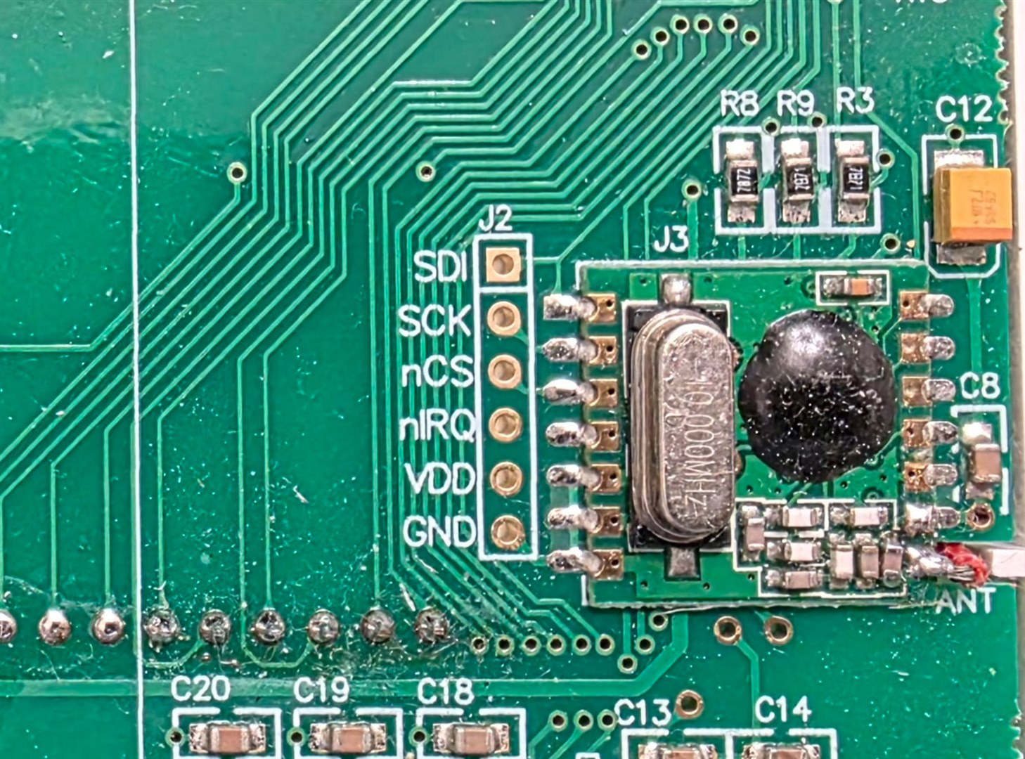
I was able to partially figure it out by probing around inside the transmitter, but the transmitter module was a black box (an unlabelled blob). I managed to narrow it down to possibly a Silicon Labs (Silabs) chipset range - perhaps Si443x series, and capture some of the bitstream using a logic analyzer.
It was a weird system, it used an out-of-band SPI interface for configuration, but the actual transmission was controlled through a kind of direct signal used for modulation on-the-fly (i.e. not a packet-oriented transfer from the microcontroller to the transmitter chip), at around 9600 bits per second, for a duration of about 176 bits. You can see this in the screenshot below, where firstly some of the purple data (configuration data) is sent together with the blue SPI clock signal, but then a load of purple data is sent without the blue clock signal changing. That clock-less portion of purple data is the direct signal that modulates the transmission, and that period length was measured to be 176 bits long, if the speed is 9600 bits/sec. The yellow signal appears to be an interrupt from the transmitter IC, paced at 9600 Hz, to act as a handshake to let the microcontroller know when it can apply the next data bit.
I didn’t manage to narrow down the SPI content to any specific chip, so I had no idea what frequency or modulation scheme was set up.

FPC Configuration
I decided to capture the transmission using the FPC1500 using its Digital Demodulation functionality. Here’s how I did it. The photo below shows in red all the buttons used.
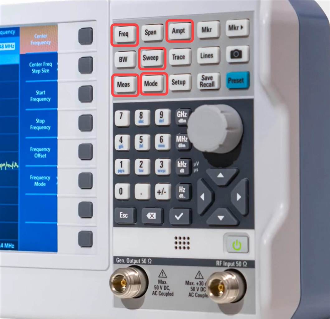
I took a guess at the frequency being ballpark 868 MHz (easy to see from the length of the antenna wire inside the transmitter, but if you're unsure, just observe a span of spectrum until you see activity) and pressed Freq and set the FPC1500 center frequency to that value.
I pressed Ampt (Amplitude) and set the reference level to -20 dBm. Next, I pressed the Mode button and selected Digital Demodulation. Then I pressed the Meas button, and selected FSK (Frequency Shift Keying; I could have selected ASK [Amplitude Shift Keying] too). Within the Meas menu, you can configure demodulation parameters. I set the Symbol Rate to 9600, and Frequency Deviation to 5 kHz (since I expected it to be around that ballpark), and then set Number of Symbols to 176.
The FPC1500 needs to be told when to trigger to capture the data; to do that, I pressed Sweep, then selected Trigger, then selected IQ Power and set it to -30 dBm, again this was just a guess, it’s not too critical.
To view the captured data, I clicked on Meas again, then clicked on Symbols, for the binary data display whenever the trigger power level occurs.
Capturing the Data
I connected the FPC's RF input to a small 868 MHz antenna and placed it near the transmitter, and voila! The FPC1500 triggered and displayed all the binary data. If you look at the binary symbols in the screenshot, you'll see the signature of a healthy transmission, because it begins with an alternating pattern of ones and zero's, which is almost always a "preamble" sequence to train the receiver to get ready to receive the rest of the bits of data.
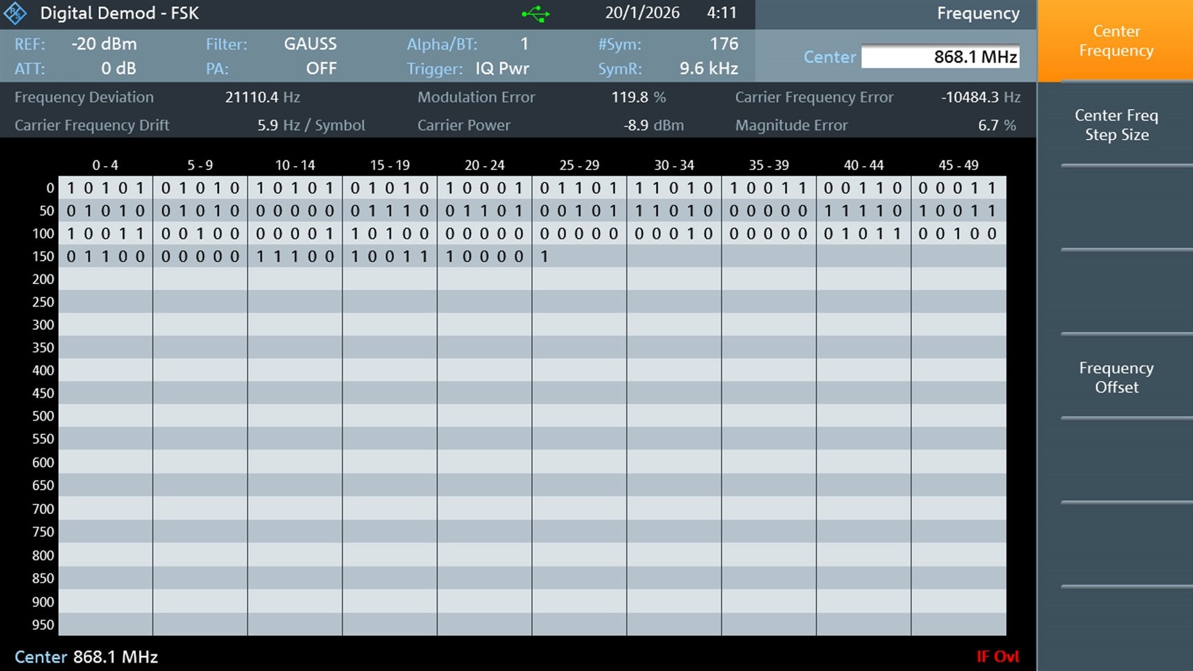
I manually typed the bit values into my PC (there may be a way to export it, but it’s not a lot of data), and then I was able to match it to the earlier logic analyzer capture. There was a slippage of 6 bits, but that’s not a big deal; I let AI (ChatGPT) figure that out.
Next Steps
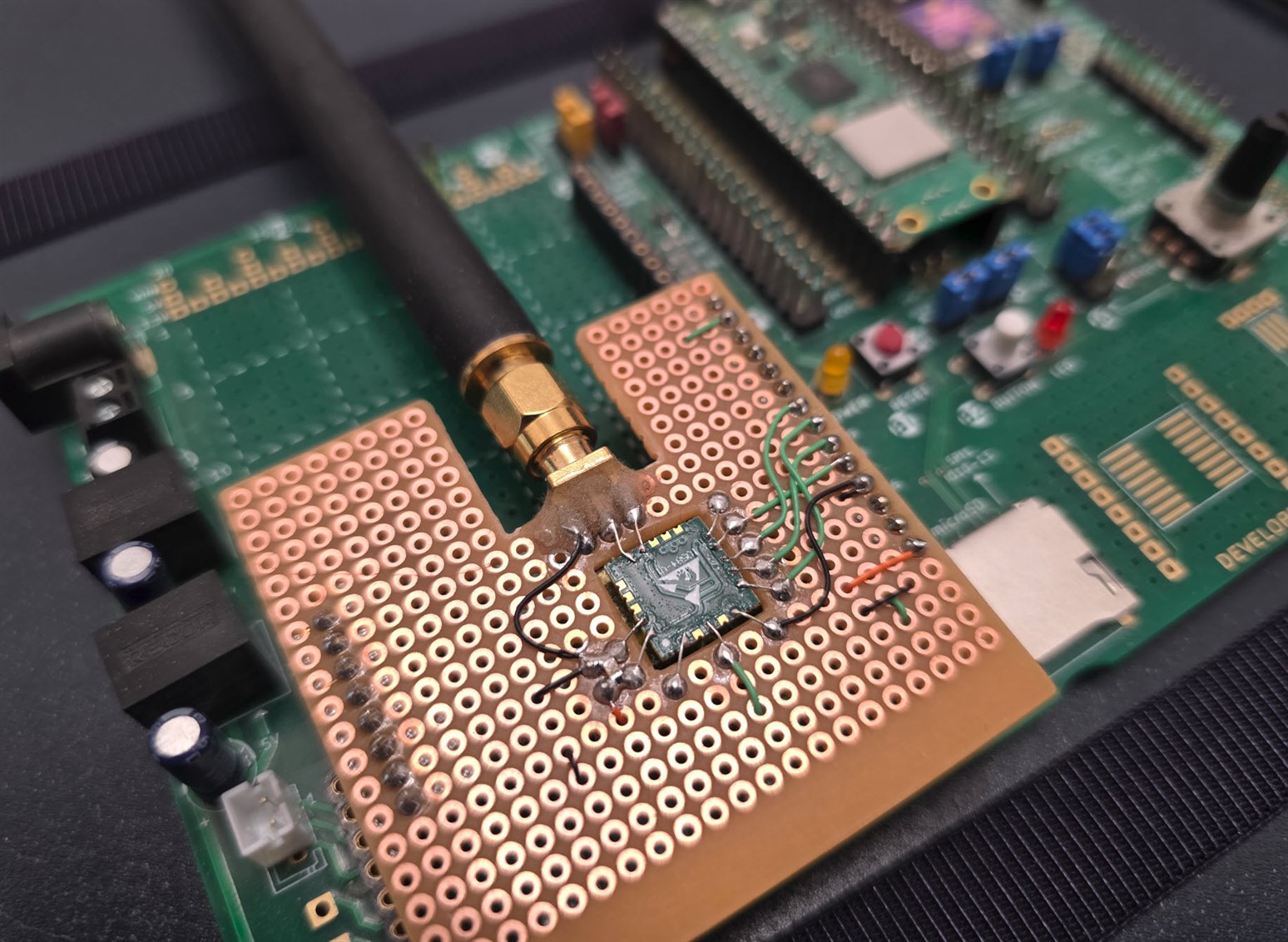
Now that I knew the approximate frequency and modulation details, it would be possible to replicate things with a custom transmitter circuit. I decided to use a Texas Instruments CC1101 chip, since that’s super-flexible (and overkill admittedly). I purchased an EBYTE E07-900MM10S module (which contains a CC1101 inside) because it’s low-cost and has pads that are easyish to solder.
I attached the EBYTE module to a Pi Pico module, and wrote code to replicate the transmission. I used the R&S FPC Digital Demodulation functionality to troubleshoot the code, until the symbols looked similar, and then verified that it did indeed control the boiler. That still needs documenting, and so it is a write-up for another day. The photo below shows the EBYTE module dead-bugged onto a Pico-Eurocard board.
Circuit Diagram:

Summary
The R&S FPC Spectrum Analyzer can trigger on a received radio transmission, and directly convert digital modulation schemes such as ASK and FSK into a decoded bit sequence, and it's just a few button presses to configure it. This can be very helpful when reverse-engineering a radio transmission, or when writing code for a transmitter and using the FPC to check that the transmission is correct. If you don’t have an FPC instrument, an alternative method would be to use a software-defined radio (SDR), but usually there’s a significant learning curve with that. The FPC was far easier to use. It solved my problem and gave me control of my heating system.
Thanks for reading.
Top Comments
-

kmikemoo
-
Cancel
-
Vote Up
0
Vote Down
-
-
Sign in to reply
-
More
-
Cancel
-

shabaz
in reply to kmikemoo
-
Cancel
-
Vote Up
+1
Vote Down
-
-
Sign in to reply
-
More
-
Cancel
Comment-

shabaz
in reply to kmikemoo
-
Cancel
-
Vote Up
+1
Vote Down
-
-
Sign in to reply
-
More
-
Cancel
Children