


The video leading up to this one can be found here Raspberry PI 2.0, Windows 10 and how to drive the DAC8734 from TI (AKA the DAC8734EVM Road test Board),
This is the third Raspberry PI 2.0, Windows 10 and how to drive the DAC8734 from TI - Software review
This post is a direct result of having issues while trying to get the DAC8734 working on the PI, in previous applications I had written on the PI and with Windows 10 for IOT, I had simply used Mode 0 SPI clocking and it worked without issues, This included many TI chips. So my assumption was that the DAC8734 would be the same. I was wrong.
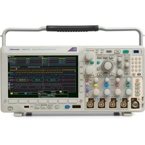
The Tektronix MDO304 proved invaluable in diagnosing this issue. things would have taken alot longer without it, nice one Tektronix, thanks.
This prompted me to put together a video and post describing the issue and showing how it was resolved. there are loads of pictures and I even managed to keep the video way under the 1Hr mark so many of you will be happy about that 
here is the rough schematic of the hardware

This is the SPI initialization routine from my code (The complete source code is available in the first post linked in above)
        public static async void InitSPI(TextBox StatusMessages)
        {
            statusText = StatusMessages; // keep pointer to status box incase of errors
            try
            {
                var settings = new SpiConnectionSettings(SPI_CHIP_SELECT_LINE);
                settings.ClockFrequency = 5000000;// 10000000;
                settings.Mode = SpiMode.Mode1; //Mode0,1,2,3;  DAC8734 needs mode 1


                string spiAqs = SpiDevice.GetDeviceSelector(SPI_CONTROLLER_NAME);
                var deviceInfo = await DeviceInformation.FindAllAsync(spiAqs);
                SpiDAC = await SpiDevice.FromIdAsync(deviceInfo[0].Id, settings);
            }


            /* If initialization fails, display the exception and stop running */
            catch (Exception ex)
            {
                statusText.Text ="\nSPI Initialization Failed";
            }
        }
you can clearly see the mode setting statement Spi.mode1 and the setting of the clock requency
the DAC8734 can run up to 50Mhz but as this was on a breadboard, the best i tried was 20Mhz, the clock was a nice sine wave by this time but still working
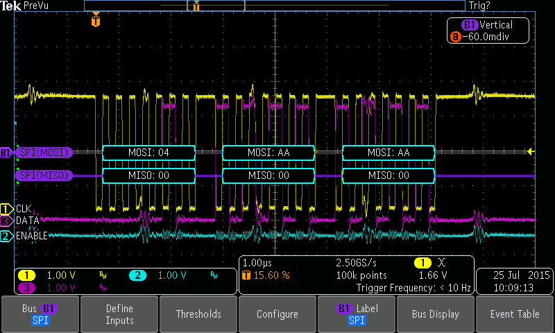
Here is a trace of the SPI but in mode 0, it was not working even though the scope was happily decoding it correctly. .
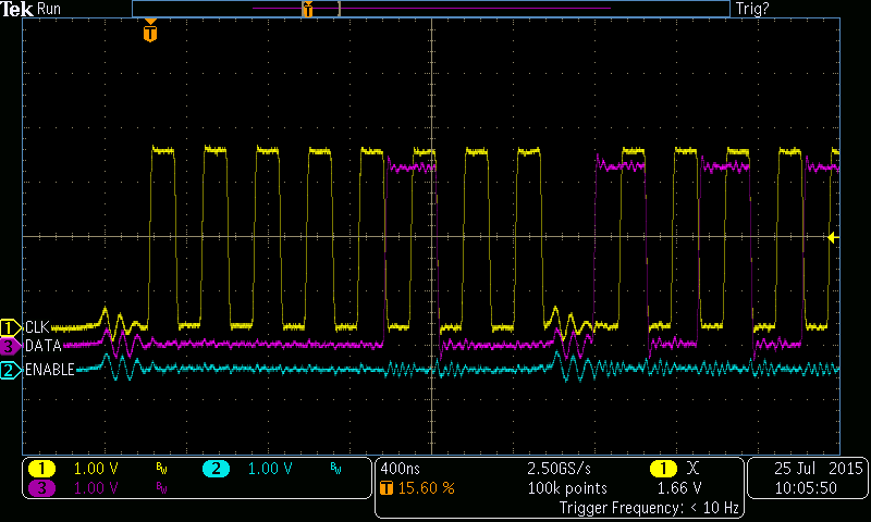

I had to refer to the PDF data sheet and closly examin the timing diagrams in order to figure it out (I guess I could have simply fliped a few parameters in the code too but then I would not learn as much. As there was little information outside of the PDF I had been able to find including a lack of sample code it was down to sleuthing. There was no mention in the data sheet of the right mode
so time to compare diagrams, here is the one from the PDF
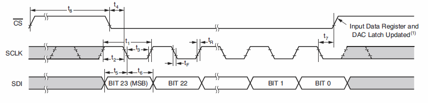
It can be clearly be seen that the timeing was wrong on the scope even though the scope was decoding it correctly (Tek is too cleaver for its own good, it defaulted to mode 0 too . the PDF is showing the clock falling edge is the one to use to latch in the data but the scope is showing it using the rising edge
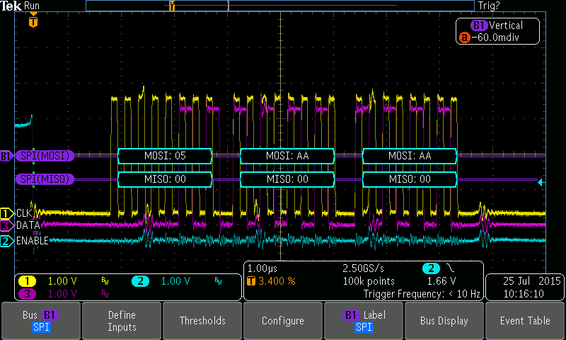
Switching the mode to 1 resulted in this trace
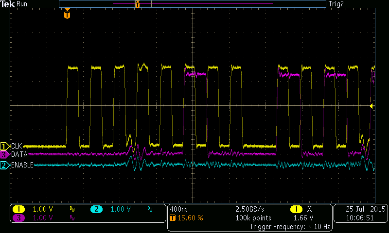
Bingo, the DAC was now responding reliably to my commands. Job done.
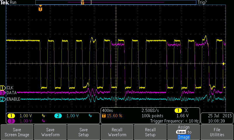
But in an effort to provide a little more education I went further and captured a bunch of traces with each mode from 0 through to 3 so you can clearly see the differences in the clocking in relation to the data
Mode 0 (Normally low level clock when idle, clocking in the data on the rising edge ). Yellow trace is the clock if you did not get that already . Purple is the data and blue is the chip select (Off screen start due to a slow Win10IOT SPI driver)
Mode 1 (Normally Low clock when idle, clocking in the data on the falling edge of the clock). This race is outputting to dac 1 which is why the first byte is a 5, Register offset to the DAC output register)
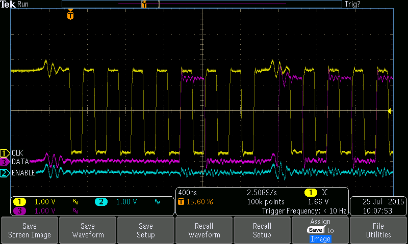
Mode 2 (Normally high level clock when idle, clocking in the data on the rising edge ).
and finally
Mode 3 (Normally high clock when idle, clocking in the data on the falling edge of the clock).
One of the other issues I had was trying to get a sine wave out of the DAV using the Raspberry PI, this should have been possible to get a reasonable output frequency as I had already got upto 250Htz from a Launchpad using a tehnique of itterating through a 256 Entry 16Bit sime table array. simple right. well yes untill you fin the SPI drivers are running really slow. I am not refering to the actual clocking of the data, as you can see above int he traces, this is working fine. The issue as it ended up being is in the drivers time to return to the running application
If I run a loop of 255 cycles it takes over 11 seconds to complete, this works out to 4mS per cycle (256 Steps) which is really slow. commenting ut the lowest call to the DAC as seen in the code below resulted int he whole loop completing in 33mS
        public static void WriteDACRegister(UInt16 register, UInt16 value)
        {
            if( ! (SpiDAC == null) && (DACInitialized == false))
            {
                DACInitialized = true;
                DAC8734.InitDAC();
            }
            byte myChannel = (byte) (register);
            writeBuffer[0] = myChannel;
            writeBuffer[1] = (byte)(value >> 8);
            writeBuffer[2] = (byte)(value & 0XFF);


            try
            {
                //SpiDAC.Write(writeBuffer);
            }


            /* If initialization fails, display the exception and stop running */
            catch (Exception ex)
            {
                statusText.Text = "\nFailed to Wrie to DAC";
            }
        }
This is the sine loop
       public static void sine(UInt16 channel, int loopcount)
        {
            statusText.Text = "Sine Loop " + loopcount * 256 + " Steps\n ";
            UInt16 myChannel = (UInt16)(DAC_8734_DataBase + channel);
            if (loopcount > 32768) loopcount = 32768;
            WriteDACRegister(myChannel, 0); // set DAC to 0 to start and init if needed
            startTime = DateTime.Now;
            for (int y = 0; y < loopcount; y++)
            {
               for (UInt16 x = 0; x < 256; x++)
               {
            WriteDACRegister(myChannel, Sin_tab[0]);
                }
            }
            endTime = DateTime.Now;
            statusText.Text += "Total Time " + ((endTime.Subtract(startTime).TotalSeconds)).ToString() + "Seconds\n";
            statusText.Text += "Sine loop Done\n";
        }
    }
and this is the table it reads from (All this is in the source code attached to the previous post)
        private static UInt16[] Sin_tab = {  32768,33572,34376,35178,35980,36779,37576,38370,39161,39947,40730,41507,42280,
                               43046,43807,44561,45307,46047,46778,47500,48214,48919,49614,50298,50972,51636,
                               52287,52927,53555,54171,54773,55362,55938,56499,57047,57579,58097,58600,59087,
                               59558,60013,60451,60873,61278,61666,62036,62389,62724,63041,63339,63620,63881,
                               64124,64348,64553,64739,64905,65053,65180,65289,65377,65446,65496,65525,65535,
                               65525,65496,65446,65377,65289,65180,65053,64905,64739,64553,64348,64124,63881,
                               63620,63339,63041,62724,62389,62036,61666,61278,60873,60451,60013,59558,59087,
                               58600,58097,57579,57047,56499,55938,55362,54773,54171,53555,52927,52287,51636,
                               50972,50298,49614,48919,48214,47500,46778,46047,45307,44561,43807,43046,42280,
                               41507,40730,39947,39161,38370,37576,36779,35980,35178,34376,33572,32768,31964,
                               31160,30358,29556,28757,27960,27166,26375,25589,24806,24029,23256,22490,21729,
                               20975,20229,19489,18758,18036,17322,16617,15922,15238,14564,13900,13249,12609,
                               11981,11365,10763,10174,9598,9037,8489,7957,7439,6936,6449,5978,5523,5085,4663,
                               4258,3870,3500,3147,2812,2495,2197,1916,1655,1412,1188,983,797,631,483,356,247,
                               159,90,40,11,1,11,40,90,159,247,356,483,631,797,983,1188,1412,1655,1916,2197,
                               2495,2812,3147,3500,3870,4258,4663,5085,5523,5978,6449,6936,7439,7957,8489,9037,
                               9598,10174,10763,11365,11981,12609,13249,13900,14564,15238,15922,16617,17322,
                               18036,18758,19489,20229,20975,21729,22490,23256,24029,24806,25589,26375,27166,
                               27960,28757,29556,30358,31160,31964};
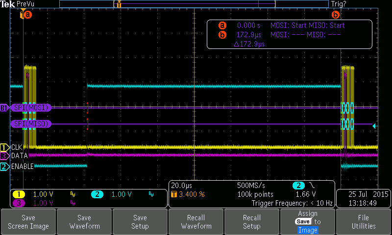
so there was clearly an issue with the Windows 10 driver (Ill report that to MS), to confirm this I captured the SPI bus across two itterations
the complete trace between two outputs, I have a cursor on to show the timing o 172.9uS, bu you can clearly see how long it takes to release the chip select line after the data has completed transmission, and then the horendious time before the next loop
this is a close up of the two bursts of data in the above trace
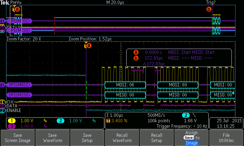

As you see, nothing wrong with the actual transmission.
here is the video, it provides much more commentry and detail, hope you like it
So I hope you find this interesting and enjoy the little walk down the dark side of SPI debugging and I hope you came away from this a little more educated about the SPI bus, I know I did.
It is actually quite a simple bus to use and at the end of the day as useual, READ THE PDF, if you get into issues then READ IT AGAIN. we all fall into the trap of thinking it is something else (And that includes me) but careful examination of the datasheet nearly always will show you the error of your ways
and secondly, just because one chip from a specific manufacturer works one way, dont assume all of them will work the same way, as was he case with me, "Assume... makes an Ass out of You and Me ". I guess were all never too old to learn we still have much to learn.
