


previous posts relating to this DAC and software
This is the last ideo and post dealing with using a Raspberry PI 2 to drive and test a DAC8734 Quad 16bit SPI bus Digital to analogue convertor from TI, and the subject of an upcomming road test
We have already reviewed the operation of the app and the DAC, we have reviewed the SPI bus and its operation (Any not operating  ), now to close things off we will walk through the code and have a quick look at deployment options and how to name your app in a frienly (er) way.
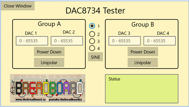
this is what the APP looks like once up and running on the PI
the first thing to look at is the code to layout the screen, if your familuar with HTML and how event handling works with ASP.net or other IDEs then it will be all too familuar, it really is all down to how the compiler and backend integration works that makes this different from older development techniques,
The Windows 10 for IOT on the PI uses XAML "Extensible Application Markup Language" , see https://en.wikipedia.org/wiki/Extensible_Application_Markup_Language
here is the code that will render theUI for the app
<Page
     x:Class="Component_Tester.MainPage"
    xmlns="http://schemas.microsoft.com/winfx/2006/xaml/presentation"
    xmlns:x="http://schemas.microsoft.com/winfx/2006/xaml"
    xmlns:local="using:Component_Tester"
    xmlns:d="http://schemas.microsoft.com/expression/blend/2008"
    xmlns:mc="http://schemas.openxmlformats.org/markup-compatibility/2006"
    mc:Ignorable="d">
    <Grid x:Name="MainGrid" Width="640" Height="360" >
        <Grid Background="#FFFDF4BF">
            <Border Margin="37,62,350,128" CornerRadius="5" BorderThickness="2" BorderBrush="Black" Width="250" Height="170">
                <Grid>
                    <TextBox x:Name="DAC1Val" HorizontalAlignment="Left" Margin="10,56,0,0" TextWrapping="Wrap" Text="" VerticalAlignment="Top"  Width="110" InputScope="Number" ToolTipService.ToolTip="Enter Value 0 - 65535" PlaceholderText="0 - 65535" TextChanged="DAC1Val_TextChanged" KeyDown="DAC1Val_KeyDown"/>
                    <TextBox x:Name="DAC2Val" HorizontalAlignment="Left" Margin="129,56,0,0" TextWrapping="Wrap" Text="" VerticalAlignment="Top" Width="110" InputScope="Number" ToolTipService.ToolTip="Enter Value 0 - 65535" PlaceholderText="0 - 65535" TextChanged="DAC2Val_TextChanged" KeyDown="DAC2Val_KeyDown"/>
                    <TextBlock x:Name="textBlock" HorizontalAlignment="Left" Margin="41,35,0,0" TextWrapping="Wrap" Text="DAC 1" VerticalAlignment="Top" RenderTransformOrigin="0.283,1.12"/>
                    <TextBlock x:Name="textBlock_Copy" HorizontalAlignment="Left" Margin="170,31,0,0" TextWrapping="Wrap" Text="DAC 2" VerticalAlignment="Top" RenderTransformOrigin="0.283,1.12"/>
                    <ToggleButton x:Name="GrpAPower" Content="Power Down" HorizontalAlignment="Left" Margin="72,93,0,0" VerticalAlignment="Top" Checked="GrpAPower_Checked" Unchecked="GrpAPower_Unchecked"/>
                    <ToggleButton x:Name="GrpAMode" Content="Unipolar" HorizontalAlignment="Left" Margin="72,130,0,0" VerticalAlignment="Top" Width="103" Checked="GrpAMode_Checked" Unchecked="GrpAMode_Unchecked"/>
                </Grid>
            </Border>
            <Border Margin="353,62,34,128" BorderThickness="2" BorderBrush="Black" CornerRadius="5" Width="250" Height="170">
                <Grid>
                    <TextBox x:Name="DAC3Val" HorizontalAlignment="Left" Margin="10,56,0,0" TextWrapping="Wrap" Text="" VerticalAlignment="Top" Width="110"  InputScope="Number" PlaceholderText="0 - 65535" ToolTipService.ToolTip="Enter Value 0 - 65535" TextChanged="DAC3Val_TextChanged" KeyDown="DAC3Val_KeyDown"/>
                    <TextBox x:Name="DAC4Val" HorizontalAlignment="Left" Margin="129,56,0,0" TextWrapping="Wrap" Text="" VerticalAlignment="Top" Width="110" InputScope="Number" PlaceholderText="0 - 65535" ToolTipService.ToolTip="Enter Value 0 - 65535" TextChanged="DAC4Val_TextChanged" KeyDown="DAC4Val_KeyDown"/>
                    <TextBlock x:Name="textBlock_Copy1" HorizontalAlignment="Left" Margin="43,35,0,0" TextWrapping="Wrap" Text="DAC 3" VerticalAlignment="Top" />
                    <TextBlock x:Name="textBlock_Copy2" HorizontalAlignment="Left" Margin="175,35,0,0" TextWrapping="Wrap" Text="DAC 4" VerticalAlignment="Top"/>
                    <ToggleButton x:Name="GrpBPower" Content="Power Down" HorizontalAlignment="Left" Margin="75,93,0,0" VerticalAlignment="Top" Checked="GrpBPower_Checked" Unchecked="GrpBPower_Unchecked"/>
                    <ToggleButton x:Name="GrpBMode" Content="Unipolar" HorizontalAlignment="Left" Margin="75,130,0,0" VerticalAlignment="Top" Width="103" Checked="GrpBMode_Checked" Unchecked="GrpBMode_Unchecked"/>
                    <TextBlock x:Name="textBlock1_Copy" HorizontalAlignment="Left" Margin="88,0,0,0" TextWrapping="Wrap" Text="Group B" VerticalAlignment="Top" RenderTransformOrigin="5.768,0.228" FontSize="21.333"/>
                </Grid>
            </Border>
            <TextBlock x:Name="textBlock1" HorizontalAlignment="Left" Margin="126,62,0,0" TextWrapping="Wrap" Text="Group A" VerticalAlignment="Top" RenderTransformOrigin="5.768,0.228" FontSize="21.333"/>
            <TextBlock x:Name="textBlock2" HorizontalAlignment="Left" Margin="220,10,0,0" TextWrapping="Wrap" Text="DAC8734 Tester" VerticalAlignment="Top" FontSize="29.333"/>
            <StackPanel Name="MainStackPanel">
                <Button Content="Close Window" Click="Button_Click" />
            </StackPanel>
            <Image x:Name="image" HorizontalAlignment="Left" Height="100" Margin="31,250,0,0" VerticalAlignment="Top" Width="257" Source="Assets/Breadboard 1440.jpg"/>
            <TextBox x:Name="txtStatus" HorizontalAlignment="Left" Margin="355,250,0,0" TextWrapping="Wrap" Text="Status" VerticalAlignment="Top" Height="100" Width="250" IsReadOnly="True" Background="#FFB8EC2D"/>
        </Grid>
        <Grid Margin="289,71,276,151">
            <RadioButton x:Name="radioD1" Content="1" HorizontalAlignment="Left" VerticalAlignment="Top" Height="152" Width="67" IsChecked="True" Margin="12,-2,-57,-12" GroupName="DACSelected"/>
            <RadioButton x:Name="radioD2" Content="2" HorizontalAlignment="Left" Height="100" Margin="12,26,-57,0" VerticalAlignment="Top" GroupName="DACSelected"/>
            <RadioButton x:Name="radioD3" Content="3" HorizontalAlignment="Left" Height="100" Margin="12,50,-57,-12" VerticalAlignment="Top" Width="67" GroupName="DACSelected"/>
            <RadioButton x:Name="radioD4" Content="4" HorizontalAlignment="Left" Height="100" Margin="12,74,-57,-36" VerticalAlignment="Top" Width="66" GroupName="DACSelected"/>
            <Button x:Name="button" Content="SINE" HorizontalAlignment="Left" VerticalAlignment="Top" Height="31" Margin="8,104,0,0" Click="button_Click_1"/>
        </Grid>
    </Grid>
</Page>
This is all of the XML to render the page, and for me this was 99% drag and drop from the tool menu in visual studio 2015 community edition RC
If you look closely you will see the statements used to hook up the event handlers that exist in the "Code Behind", and example is this TextChanged="DAC3Val_TextChanged" KeyDown="DAC3Val_KeyDown", this shows 2 event handlers for a text box, and simply wires the UI element to C# code
this is the C# code
        private void DAC3Val_KeyDown(object sender, KeyRoutedEventArgs e)
        {
            if (e.Key == Windows.System.VirtualKey.Enter)
            {
                txtStatus.Text = "You Entered: " + DAC3Val.Text + "\n";
                updateDAC(2, DAC3Val);
                //this.Focus(FocusState.Programmatic);
            }
        }
private void DAC3Val_TextChanged(object sender, TextChangedEventArgs e)
        {
            CorrectTextToUINT16(DAC3Val);
        }
The first function triggers every time a key is pressed on the element in focus (DAC3VAL in this case) and as you can see, will only really do anything if it is an enter key that was pressed
the second function triggers every time the value of the element changes, this could be because of a key press if the element was in focus, or it could be from a paste, or a code section directly changing the value , perhaps from the reading of some sensor (Not in this app though). by the way, this text box is the one directly under the words "DAC 3" in the above UI image.
As I said, if you have coded in Visual Studio before or any other language that has a graphical designer and supports event handling then it will be all too familuar. I am not going to try to teach you how to code here, just show you how to drive the DAC8734. We just need a UI in this case to do that. for the rest of the elements on this page, I will leave you to review the code yourself, if you have any questions, by all meand add a comment below and Ill try to answer them for you
OK, so now to the linrary for the DAC itself, I have for now simply created this as a static class, meaning you dont need to instansiate it before using it. The class wrapps up the instracities of using the DAC from the UI, allowing the developmer to focus on the APP instead of how to make the chip work
here is the library
using System;
using Windows.UI.Xaml.Controls;
using Windows.Devices.Spi;
using Windows.Devices.Enumeration;

namespace DAC.DAC8734
{
    public class DAC8734
    {
        private const UInt16 DAC_8734_Command = 0; // command register
        private const UInt16 DAC_8734_DataBase = 0x04; // register offset to zero cal base register
        private const UInt16 DAC_8734_CalZeroBase = 0x08; // register offset to zero cal base register
        private const UInt16 DAC_8734_CalGainBase = 0x0C; // register offset to gain cal base register

        private const UInt16 DACMAX = 0xFFFF;
        private const UInt16 DACMIN = 0x0000;

        private static UInt16 DAC_Gain0 = 0; // 0 = *2, 1 = *4
        private static UInt16 DAC_Gain1 = 0; // 0 = *2, 1 = *4
        private static UInt16 DAC_Gain2 = 0; // 0 = *2, 1 = *4
        private static UInt16 DAC_Gain3 = 0; // 0 = *2, 1 = *4
        private static UInt16 DAC_GPIO0 = 1; // 1 = Group A in bipolar 0=Unipolar (External connection to control pin)
        private static UInt16 DAC_GPIO1 = 1; // 1 = Group B in bipolar 0=Unipolar (External connection to control pin)
        private static UInt16 DAC_PD_A = 0; // 1 = group A power down
        private static UInt16 DAC_PD_B = 0; // 1 = group B power down
        private static UInt16 DAC_DSDO = 0; // 1 = Disable SDO bit.

        //// Sine table for if we want to output a waveform
        private static byte val = 0;
        private static UInt16[] Sin_tab = {  32768,33572,34376,35178,35980,36779,37576,38370,39161,39947,40730,41507,42280,
                               43046,43807,44561,45307,46047,46778,47500,48214,48919,49614,50298,50972,51636,
                               52287,52927,53555,54171,54773,55362,55938,56499,57047,57579,58097,58600,59087,
                               59558,60013,60451,60873,61278,61666,62036,62389,62724,63041,63339,63620,63881,
                               64124,64348,64553,64739,64905,65053,65180,65289,65377,65446,65496,65525,65535,
                               65525,65496,65446,65377,65289,65180,65053,64905,64739,64553,64348,64124,63881,
                               63620,63339,63041,62724,62389,62036,61666,61278,60873,60451,60013,59558,59087,
                               58600,58097,57579,57047,56499,55938,55362,54773,54171,53555,52927,52287,51636,
                               50972,50298,49614,48919,48214,47500,46778,46047,45307,44561,43807,43046,42280,
                               41507,40730,39947,39161,38370,37576,36779,35980,35178,34376,33572,32768,31964,
                               31160,30358,29556,28757,27960,27166,26375,25589,24806,24029,23256,22490,21729,
                               20975,20229,19489,18758,18036,17322,16617,15922,15238,14564,13900,13249,12609,
                               11981,11365,10763,10174,9598,9037,8489,7957,7439,6936,6449,5978,5523,5085,4663,
                               4258,3870,3500,3147,2812,2495,2197,1916,1655,1412,1188,983,797,631,483,356,247,
                               159,90,40,11,1,11,40,90,159,247,356,483,631,797,983,1188,1412,1655,1916,2197,
                               2495,2812,3147,3500,3870,4258,4663,5085,5523,5978,6449,6936,7439,7957,8489,9037,
                               9598,10174,10763,11365,11981,12609,13249,13900,14564,15238,15922,16617,17322,
                               18036,18758,19489,20229,20975,21729,22490,23256,24029,24806,25589,26375,27166,
                               27960,28757,29556,30358,31160,31964};

        private static UInt16[] DAC_CAL_tab = { 0xFF, 0xfF, 0x50, 0x5F, 0x80, 0x80, 0x80, 0x80 }; // zero's then gain's
        private static bool DACInitialized = false;

        /*RaspBerry Pi2  Parameters*/
        private const string SPI_CONTROLLER_NAME = "SPI0";  /* For Raspberry Pi 2, use SPI0                             */
        private const Int32 SPI_CHIP_SELECT_LINE = 1;       /* Line 0 maps to physical pin number 24 on the Rpi2, line 1 to pin 26        */

        static byte[] readBuffer = new byte[3]; /*this is defined to hold the output data*/
        static byte[] writeBuffer = new byte[3];//register, then 16 bit value

        private static SpiDevice SpiDAC;
        private static TextBox statusText;

        public static async void InitSPI(TextBox StatusMessages)
        {
            statusText = StatusMessages; // keep pointer to status box incase of errors
            try
            {
                var settings = new SpiConnectionSettings(SPI_CHIP_SELECT_LINE);
                settings.ClockFrequency = 5000000;// 10000000;
                settings.Mode = SpiMode.Mode1; //Mode0,1,2,3;  DAC8734 needs mode 1


                string spiAqs = SpiDevice.GetDeviceSelector(SPI_CONTROLLER_NAME);
                var deviceInfo = await DeviceInformation.FindAllAsync(spiAqs);
                SpiDAC = await SpiDevice.FromIdAsync(deviceInfo[0].Id, settings);
            }
            /* If initialization fails, display the exception and stop running */
            catch (Exception ex)
            {
                statusText.Text ="\nSPI Initialization Failed";
            }
        }

        // DAC STUFF
        public static void CalDAC()
        {
            for (int x = 0; x < 4; x++)
            {
                WriteDACRegister((UInt16)(DAC_8734_CalZeroBase + x), DAC_CAL_tab[x]);// Zero cal
                WriteDACRegister((UInt16)(DAC_8734_CalGainBase + x), DAC_CAL_tab[x + 4]); // Gain cal
            }
        }

        public static void InitDAC()
        {
            // for now, gain of 2, gpio hiZ,
            UInt16 DAC_INIT =  (UInt16)(0x0000 | DAC_PD_A << 12 | DAC_PD_B << 11 | DAC_GPIO1 << 9 | DAC_GPIO0 << 8 | DAC_DSDO << 7 | DAC_Gain3 << 5 | DAC_Gain2 << 4 | DAC_Gain1 << 3 | DAC_Gain0 << 2);
            statusText.Text = "\nCmd Reg = " + DAC_INIT.ToString("X4") + " " + Convert.ToString(DAC_INIT, 2) + "\n";
            WriteDACRegister(DAC_8734_Command, DAC_INIT);
        }

        public static void WriteDACData(UInt16 channel, UInt16 value)
        {
            WriteDACRegister((UInt16)(DAC_8734_DataBase + channel), value);
        }

        public static void WriteDACRegister(UInt16 register, UInt16 value)
        {
            if( ! (SpiDAC == null) && (DACInitialized == false))
            {
                DACInitialized = true;
                DAC8734.InitDAC();
            }
            byte myChannel = (byte) (register);
            writeBuffer[0] = myChannel;
            writeBuffer[1] = (byte)(value >> 8);
            writeBuffer[2] = (byte)(value & 0XFF);
            try
            {
                SpiDAC.Write(writeBuffer);
            }
            /* If initialization fails, display the exception and stop running */
            catch (Exception ex)
            {
                statusText.Text = "\nFailed to Wrie to DAC";
            }
        }

        public static void powerDownGrpA()
        {
            statusText.Text = "\n GroupA Powered Down";
            DAC_PD_A = 1;
            InitDAC();
        }
        public static void powerUpGrpA()
        {
            statusText.Text = "\n GroupA Powered Up";
            DAC_PD_A = 0;
            InitDAC();
        }
        public static void modeUnipolarGrpA()
        {
            statusText.Text = "\n GroupA Unipolar Mode Set";
            DAC_GPIO0 = 0;
            InitDAC();
        }
        public static void modeBipolarGrpA()
        {
            statusText.Text = "\n GroupA Bipolar Mode Set";
            DAC_GPIO0 = 1;
            InitDAC();
        }
        public static void powerDownGrpB()
        {
            statusText.Text = "\n GroupB Powered Down";
            DAC_PD_B = 1;
            InitDAC();
        }
        public static void powerUpGrpB()
        {
            statusText.Text = "\n GroupB Powered Up";
            DAC_PD_B = 0;
            InitDAC();
        }
        public static void modeUnipolarGrpB()
        {
             statusText.Text = "\n GroupB Unipolar Mode Set";
           DAC_GPIO1 = 0;
            InitDAC();
        }
        public static void modeBipolarGrpB()
        {
            statusText.Text = "\n GroupB Bipolar Mode Set";
            DAC_GPIO1 = 1;
            InitDAC();
        }


        private static DateTime startTime;
        private static DateTime endTime;

        public static void sine(UInt16 channel, int loopcount)
        {
            statusText.Text = "Sine Loop " + loopcount * 256 + " Steps\n ";
            UInt16 myChannel = (UInt16)(DAC_8734_DataBase + channel);
            if (loopcount > 32768) loopcount = 32768;
            WriteDACRegister(myChannel, 0); // set DAC to 0 to start and init if needed
            startTime = DateTime.Now;
            for (int y = 0; y < loopcount; y++)
            {
               for (UInt16 x = 0; x < 256; x++)
               {
            WriteDACRegister(myChannel, Sin_tab[0]);
                }
            }
            endTime = DateTime.Now;
            statusText.Text += "Total Time " + ((endTime.Subtract(startTime).TotalSeconds)).ToString() + "Seconds\n";
            statusText.Text += "Sine loop Done\n";
        }
    }
}
As you can see, there not a huge amount to it, loads of little functions to make life easyer for the developer of the UI, but basically it boild down to the following functions that really matter, the rest are just helpers
public static void WriteDACRegister(UInt16 register, UInt16 value)
{
if( ! (SpiDAC == null) && (DACInitialized == false))
{
DACInitialized = true;
DAC8734.InitDAC();
}
byte myChannel = (byte) (register);
writeBuffer[0] = myChannel;
writeBuffer[1] = (byte)(value >> 8);
writeBuffer[2] = (byte)(value & 0XFF);
try
{
SpiDAC.Write(writeBuffer);
}
/* If initialization fails, display the exception and stop running */
catch (Exception ex)
{
statusText.Text = "\nFailed to Wrie to DAC";
}
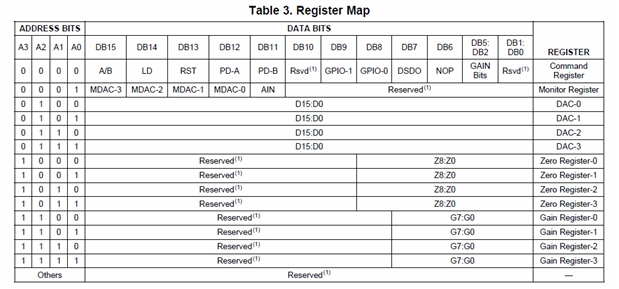
}This function takes a register value (16 Bit, and a register offset (Device dependent, but here is a list for the DAC8734)
and it simply creates a 3 byte buffer, the first being the register value, the next wo the data, high order byte first, high order bit first, for different devices, this buffer will be simply changed to reflect the data requirements of your device
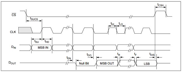
Here is a sample SPI bus capture that shows the data 0xAAAA (Hex) being sent to register 5 (The DAC1 data register
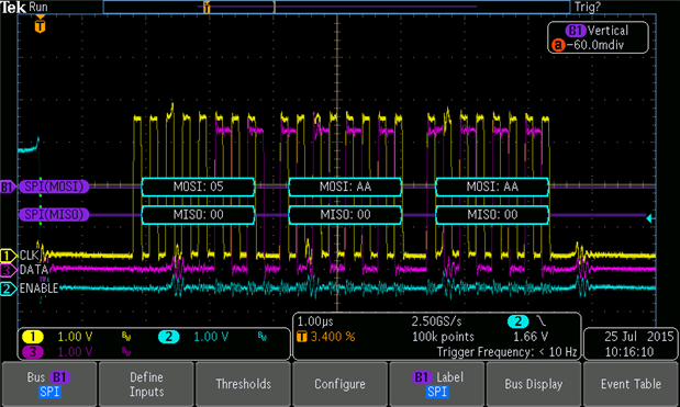
It is important to review the data sheet when deviding which mode of the SPI clocking you need to use
this above is for the DAC8734 and corresponds to Mode 1. other vendor including TI devices may need different modes
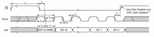
for instance, this is the timing for a Microchip MCP3208 and as you can see, it needs mode 0
Notice the difference in the clocking edge
Anyway, this brings us to the other most important function, the SPI Initialization function "InitSPI". this is slightly modified from the MS samples as I added a parameter to allow me to pass in a handle to a text box on the UI, allowing me to output debug messages directly to the UI without having to worry about return codes etc. This would not be a normal practice for production code.
there are four properties that vary with this function. The SPIx bus name, the SPI Chip select name, the Mode of operation (See the previous video for more examples of this) and the bus speed.
The speed is not as critical as the other parameters as the whole bus is edge triggered and therefor will work for most speeds. I easily changed from a few kHtz to 20Mhz and the device did not care. Cabling, LOAD and termination etc will define how fast you will be able to drive your bus, so really you only need to go as fast as your application needs. which may be way slower than the MAX of 50Mhz for the DAC8734.
        /*RaspBerry Pi2  Parameters*/
        private const string SPI_CONTROLLER_NAME = "SPI0";  /* For Raspberry Pi 2, use SPI0                             */
        private const Int32 SPI_CHIP_SELECT_LINE = 1;       /* Line 0 maps to physical pin number 24 on the Rpi2, line 1 to pin 26        */

public static async void InitSPI(TextBox StatusMessages)
        {
            statusText = StatusMessages; // keep pointer to status box incase of errors
            try
            {
                var settings = new SpiConnectionSettings(SPI_CHIP_SELECT_LINE);
                settings.ClockFrequency = 5000000;// 10000000;
                settings.Mode = SpiMode.Mode1; //Mode0,1,2,3;  DAC8734 needs mode 1


                string spiAqs = SpiDevice.GetDeviceSelector(SPI_CONTROLLER_NAME);
                var deviceInfo = await DeviceInformation.FindAllAsync(spiAqs);
                SpiDAC = await SpiDevice.FromIdAsync(deviceInfo[0].Id, settings);
            }


            /* If initialization fails, display the exception and stop running */
            catch (Exception ex)
            {
                statusText.Text ="\nSPI Initialization Failed";
            }
        }
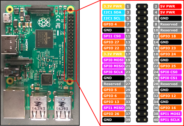
The "SPI_CHIP_SELECT_LINE" is a constant and is either 0 or 1 for SPI0, it can only be 0 for SPI1 (This is the supported features on the PI), the chip selects corespond to the respective pins on the PI GPIO, note that SPI1 and SPI0 also have different MOSI, MISO and SCLK lines meaning you can have upto 3 physical SPI devices on the PI (This may be more logical than physical as there are techniques that allow multiple devices to share a single CSz line, this includes the DAC8734 that can be daisy chained with other DAC8734s.
So, Finally here is the video where I walk you through the above code with a little more detal and examine more of the code
I have re-attached the code in zip format for you to review and use as you please. Hope you enjoy it