|
For the Sound and Vibration Measurement Hat for Raspberry Pi road test, I'm reviewing Measurement Computing's IEPE Measurement DAQ HAT for Raspberry Pi. video: flow sweeping from 20 to 40 Hz, taking 64 samples each time and average them This is a showcase. I'm trying to prove that the MCC172 hat can be used in combination with other lab instruments (a function generator) and that you can do stats on the DAQ data real time. It does In-Stream RMS calculation over a set of samples at every frequency. And that the driver for the DAQ is up to the job. |
Vibration Jig Test Flow
The jig is a shaking device that will vibrate a device under test at a given frequency, and measure the acceleration force. You can set amplitude, frequency range, sample speed and steps. Then the flow will sweep through that range. The MCC172 DAQ will acquire a (high) number of steps at each frequency increment. That data is then processed - I used RMS in this example because I'm dealing with a sinus input and it's a nice example for a proof of concept. The result is written to a spreadsheet, one record per frequency increment.
The shaker's frequency and amplitude are controlled by a Multicomp PRO MP750065 function generator. I created a LabVIEW driver for that a while ago, and that turns out to be of big value in this project.
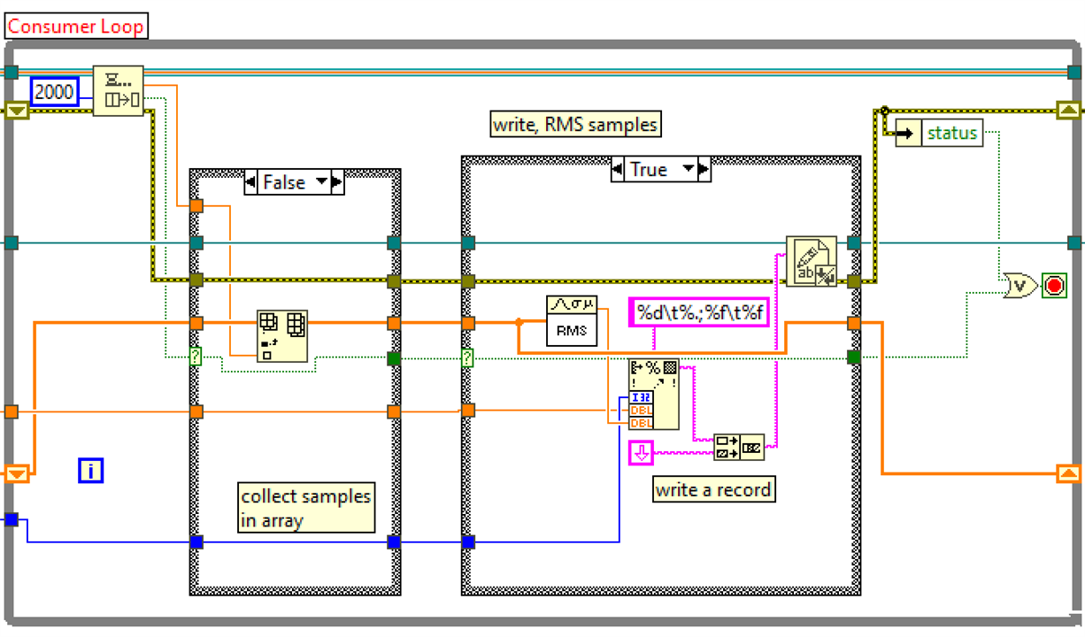
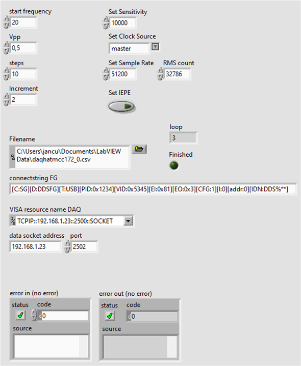
Below is the RMS calculation flow. It gets called each time the frequency is incremented by the test software. I have configured it to take 32.786 samples per frequency, with a rate of 51.200 samples per second.
It feeds the 32.786 into an array. When done, LabVIEW calculates the RMS of that dataset. The result is then written to the file. The whole process - including changing the frequency - takes a few seconds per increment. Most of the time I wait for the jig to stabilise after a frequency hike.

Here you can see the process in action.
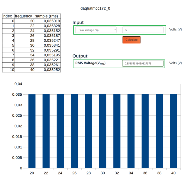
These settings were used to generate the output below: 11 buckets of 32K measurements, from 20 to 40 Hz with 2 Hz increments. Behind this 11 row spreadsheet are 360.448 samples !! The whole process took 33 seconds, including file write.
RMS calculation: https://www.allaboutcircuits.com/tools/rms-voltage-calculator/
A very careful reader will see that the measurements are off with an order of magnitude. That's because I used a sensitive setting of 10.000 to adjust for the output per gram of the Piezo sensor that I'll use in the final jig design.
The full flow can be seen in the video at the top of this post. It's also available on the project's github.

