|
For the Sound and Vibration Measurement Hat for Raspberry Pi road test, I'm reviewing Measurement Computing's IEPE Measurement DAQ HAT for Raspberry Pi.
|
What Is It
The shield is a 2 channel ADC with local control and auxiliary power supplies. It's specialised in sampling piezo sensors and microphones, to gather audio and vibration metrics.
It's job is to acquire a lot of data fast, and send it to a Raspberry Pi host.
Analogue specifications:
- 2 ADC channels, delta sigma, channels can be synced
- 5 V AC
- from +- 1 Hz on
- 24-bit
- 50.000 samples per second
- IEPE power supply for each channel, switchable, 23 V compliance, typical 4 mA constant current.
This means it can deliver 4mA constantly as long as the required voltage to do so doesn't exceed 23 V.
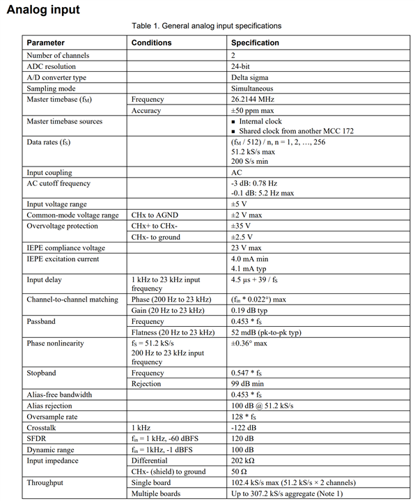
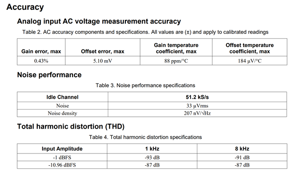
images source: electrical specifications
Digital specifications:
- Digital trigger input
- local µcontroller and fifo data buffer that can hold 49000 samples
- Raspberry Pi as host, interfaced via SPI
- Stackable, a single Pi can host several shields of this family. It can handle up to 3 boards at full speed on both channels.
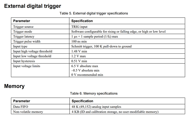
image source: electrical specifications
Power:
- The Pi supplies the required power. A local switch mode supply boosts that for the IEPE sensor supply.
What's on the board
Goodies!
On the input side, there's a set of Burr-Brown ICs.
The ADCs are ADS1271.
Input is buffered by a 2 channel OPA2277U OpAmp.
From TI proper, there's the THS4531A differential amp in each channel, between the inpu buffer and ADC.
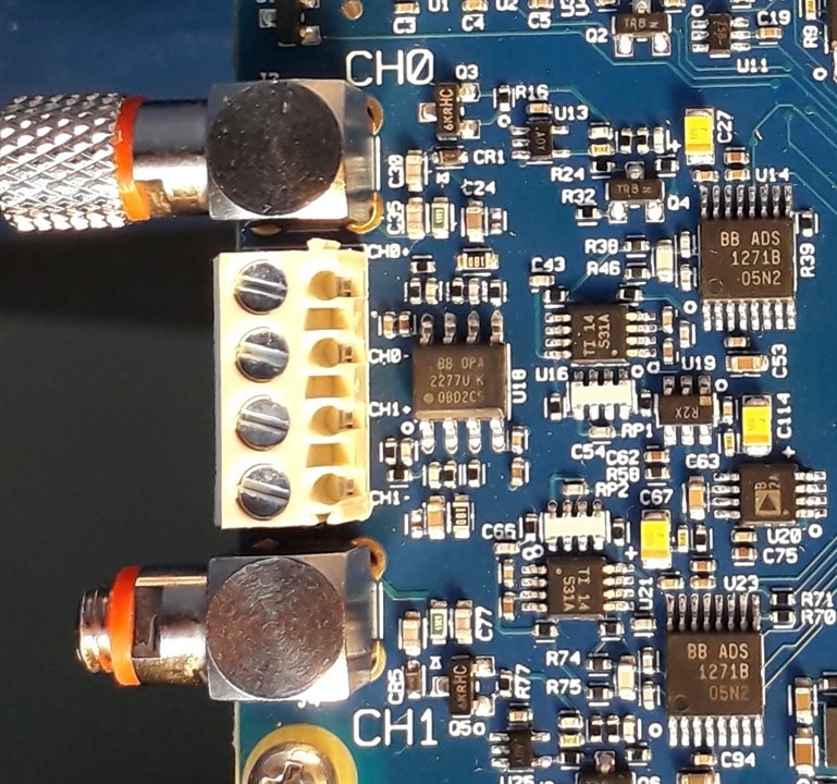
There's an Analog Devices IC on the input area, with marking B 2A. I couldn't find what that is yet.
In the IEPE supply, there's another AD that seems to be the boost converter. There's another SMPS to the right of that.
On the controller side, you find an Atmel SAM G55 ARM Cortex M4.
CSI 24C32WI 32 Kb i2c EEPROM for calibration data.
I haven't found the memory for the FIFO. That may be part of the SAM G55 RAM.
Under the two SMPS, I think that there's another DC converter. I first thought it was the digital trigger protection circuit, but I think I see a FET and inductor and somewhat beefy traces....
For the sleuths on the forum, I've taken a (for my doing) detailed photo. Maybe you can find more, or you see errors in my overview?
Warning: this image is 1.6 MB when you click on it.
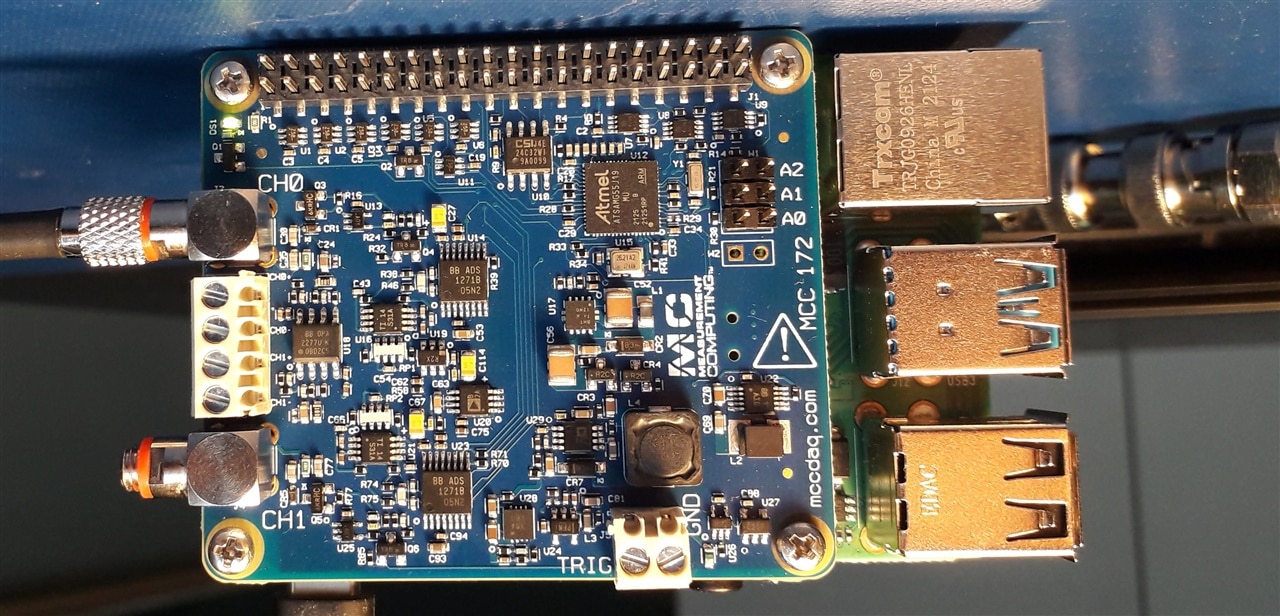
The markings on some of the ICs on the right part of the board are clearer on a photo available from Digilent's production page.


