|
For the Sound and Vibration Measurement Hat for Raspberry Pi road test, I'm reviewing Measurement Computing's IEPE Measurement DAQ HAT for Raspberry Pi. The DAQ Hat is a 2 channel sensor data acquisition device. And a power supply for IEPE (Integrated Electronics Piezo-Electric) sensors. This post is early in my road test exercise - I'm still learning. But it shows how my future test jig will work together with the components.
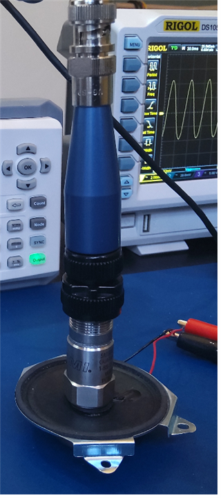
I'm using the FFT C example . If all works fine (and it does) it should detect at what frequency my test jig vibrates, and show buckets for the harmonics. |
Test setup
I'm preparing a vibration test gizmo. A test bed to validate how products physically behave when being shaken.
In its first build, it's a small speaker (0.5W, 8Ω), driven by the power output of a function generator.

The 603C01 IEPE piezo sensor, part of the road test kit, sits firmly in the middle of the speaker.
There's no glue or mechanical connection. At this moment, gravity does the job. Good enough if I stay away from the mechanical resonance frequency of the combination.
The sensor is connected to channel 0 of the MCC 172 DAQ. I've attached my oscilloscope to learn a few things:
- what does the sensor signal look like?
- can I see the IEPE injected DC? When is it injected.
This is a very simple setup, with as only goal to check if the combination works. Can the sensor detect small changes in the speaker's movement?
FFT Example
I want to check if the sensor can detect the tiny speaker movements, and if the vibration frequency can be measured.
I'm using the C FFT example that comes with the DAQ.
It will try to find the base frequency based on the data returned by the sensor.
Then, it 'll show the signal strength at that frequency (in dB), and buckets for the harmonics.
Before starting the (very short) measurement, it asks if the sensor needs IEPE power. It does, for the 603C01.
Results
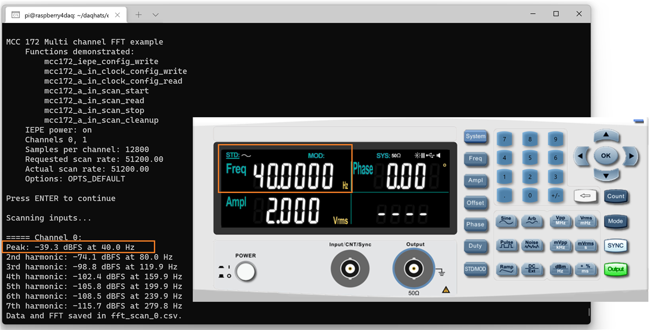
I've tested the setup for 2 frequencies, 36 Hz and 40 Hz. Both time, I sent 2 VRMS to the speaker: 1/4 W.
Here are the results. Ignore the Channel 1 readings, because there's no sensor attached.


Both times, the program was able to detect the peak frequency, then make buckets for the harmonics.
In the photo at the top of this post, you can also see the signal on the oscilloscope.
Before taking the photo, I also put the scope in DC, to see the IEPE voltage. It's just above 25 V dc.
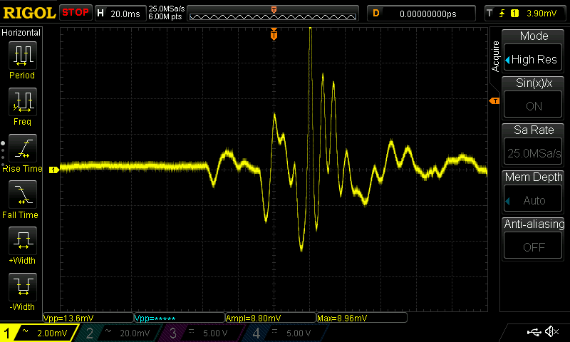
As a little final test, I put the sensor on my table, and performed a quick tap of three fingers on the table top.
With the scope in single shot, here's how that looks:

This is just the first little post. There's much more to come ...
The little demo below shows the FFT in action in LabVIEW, and also acceleration calculation. All of that is developed in posts further down the line.


