element14 Community
element14 Community
    Register Log In
  • Site
  • Search
  • Log In Register
  • Community Hub
    Community Hub
    • What's New on element14
    • Feedback and Support
    • Benefits of Membership
    • Personal Blogs
    • Members Area
    • Achievement Levels
  • Learn
    Learn
    • Ask an Expert
    • eBooks
    • element14 presents
    • Learning Center
    • Tech Spotlight
    • STEM Academy
    • Webinars, Training and Events
    • Learning Groups
  • Technologies
    Technologies
    • 3D Printing
    • FPGA
    • Industrial Automation
    • Internet of Things
    • Power & Energy
    • Sensors
    • Technology Groups
  • Challenges & Projects
    Challenges & Projects
    • Design Challenges
    • element14 presents Projects
    • Project14
    • Arduino Projects
    • Raspberry Pi Projects
    • Project Groups
  • Products
    Products
    • Arduino
    • Avnet & Tria Boards Community
    • Dev Tools
    • Manufacturers
    • Multicomp Pro
    • Product Groups
    • Raspberry Pi
    • RoadTests & Reviews
  • About Us
  • Store
    Store
    • Visit Your Store
    • Choose another store...
      • Europe
      •  Austria (German)
      •  Belgium (Dutch, French)
      •  Bulgaria (Bulgarian)
      •  Czech Republic (Czech)
      •  Denmark (Danish)
      •  Estonia (Estonian)
      •  Finland (Finnish)
      •  France (French)
      •  Germany (German)
      •  Hungary (Hungarian)
      •  Ireland
      •  Israel
      •  Italy (Italian)
      •  Latvia (Latvian)
      •  
      •  Lithuania (Lithuanian)
      •  Netherlands (Dutch)
      •  Norway (Norwegian)
      •  Poland (Polish)
      •  Portugal (Portuguese)
      •  Romania (Romanian)
      •  Russia (Russian)
      •  Slovakia (Slovak)
      •  Slovenia (Slovenian)
      •  Spain (Spanish)
      •  Sweden (Swedish)
      •  Switzerland(German, French)
      •  Turkey (Turkish)
      •  United Kingdom
      • Asia Pacific
      •  Australia
      •  China
      •  Hong Kong
      •  India
      •  Korea (Korean)
      •  Malaysia
      •  New Zealand
      •  Philippines
      •  Singapore
      •  Taiwan
      •  Thailand (Thai)
      • Americas
      •  Brazil (Portuguese)
      •  Canada
      •  Mexico (Spanish)
      •  United States
      Can't find the country/region you're looking for? Visit our export site or find a local distributor.
  • Translate
  • Profile
  • Settings
Test & Tools
  • Technologies
  • More
Test & Tools
Forum Reverse polarity protection circuit & output backward flow control
  • Blog
  • Forum
  • Documents
  • Files
  • Members
  • Mentions
  • Sub-Groups
  • Tags
  • More
  • Cancel
  • New
Join Test & Tools to participate - click to join for free!
Actions
  • Share
  • More
  • Cancel
Forum Thread Details
  • State Verified Answer
  • Replies 21 replies
  • Answers 7 answers
  • Subscribers 360 subscribers
  • Views 4395 views
  • Users 0 members are here
  • reverse polarity protection
Related

Reverse polarity protection circuit & output backward flow control

tim687
tim687 over 8 years ago

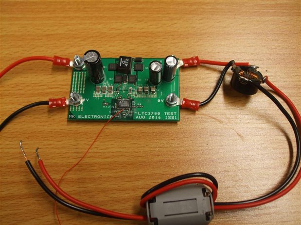
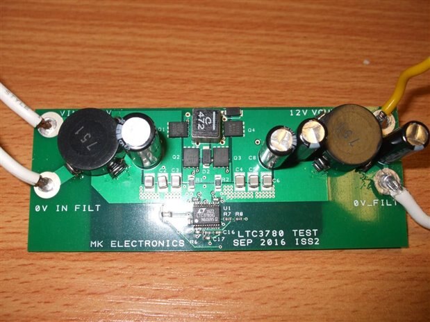
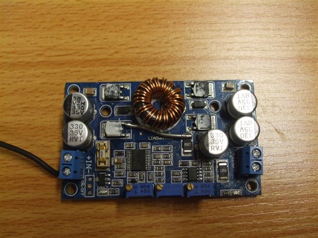
I am building my own (2 channel) lab bench. This is the conversion board I'm using to convert 12V (input) to 1-24V (one for each channel).


In the product description they say

Input reverse connect protection: No (If necessary, please input series schottky diode)
Output control flow backward: No (If used for battery charging or load is bring electricity load, please on the output side series schottky diode)

This does mean that there is no reverse polarity input protection (that is not needed anyways), but does this mean that there is reverse polarity output protection?

In the datasheet of the LTC3780 I found the following pin descriptions in the pinout:


SENSE+ (Pin 3/Pin 1):

The + Input to the Current Sense

and Reverse Current Detect Comparators. The ITH

pin voltage and built-in offsets between SENSE– and SENSE+ pins,

in conjunction with RSENSE, set the current trip threshold.

SENSE– (Pin 4/Pin 2):

The (–) Input to the Current Sense

and Reverse Current Detect Comparators.


Is this the reverse polarity protection feature and output backward flow control I'm looking for?


If yes, I don't have to design the circuitry to protect the output, if no, could you provide a solution which can accept variable voltages?

This is one solution I found very interesting due to the indicator LED and the 'no power loss' (claim).

Due to inefficiency of a schottky diode I am only going to use it if necessary.


Thanks in advance for helping me out!

  • Sign in to reply
  • Cancel

Top Replies

  • michaelkellett
    michaelkellett over 8 years ago +1 suggested
    This board will make a truly dreadful bench supply - unless you only want it to work light bulbs or heaters then please think again. I recently helped a customer trouble shoot a new design where they had…
  • rachaelp
    rachaelp over 8 years ago in reply to michaelkellett +1 suggested
    Michael Kellett wrote: For a general purpose bench supply you can't beat a decent linear design - just learn to live with the size, weight and heat MK You can also do a hybrid design to try and get the…
  • michaelkellett
    michaelkellett over 8 years ago in reply to tim687 +1 suggested
    Hello Tim, The noise is un-fixable by any reasonable means - it consists of bursts of very large amplitude 50-130 MHz decaying sine bursts as the power devices switch. We put at least 160 hours of engineering…
  • rachaelp
    0 rachaelp over 8 years ago in reply to tim687

    You basically cascade the regulators so you have Vin -> Switching Regulator -> Linear Regulator -> Vout and then you take your feedback from Vout and generate appropriate control voltages to the two regulators to ensure the switcher output remains a few volts above the final output voltage.


    I think it's unlikely that you'll get a clean enough output for your supply by just trying to filter the output with adding capacitors. You could try to create an LC filter on your output to suppress the noise but really, if you are trying the create a nice clean supply the best way is to have a linear power supply design.


    The board you are planning to use supports up to 10A or 7A for long term use but what current do you really need?


    Best Regards,


    Rachael

    • Cancel
    • Vote Up 0 Vote Down
    • Sign in to reply
    • Verify Answer
    • Reject Answer
    • Cancel
  • michaelkellett
    0 michaelkellett over 8 years ago in reply to tim687

    Hello Tim,


    The noise is un-fixable by any reasonable means - it consists of bursts of very large amplitude 50-130 MHz decaying sine bursts as the power devices switch. We put at least 160 hours of engineering time, two pcb iterations  and 2 test board designs into this. We added every possible external filter and tried countless different capacitor and inductor filter combinations. We had a 1GHz scope and a spectrum analyzer to help as well. We just could not get the power devices to switch cleanly.


    The pictures are our test board, issue 1 and 2 (note the increase in filtering) and the cheap board from Amazon (which we tweaked to no avail). I don't have a picture of the official demo board. The best one is our own with the extra filters (450mV p-p at about 75 MHz) but the the high frequency noise couples into pcb ground planes and finds its way round filters. The LT demo board gave about 800mV p-p at 90MHz. In both cases the noise takes the form of short (a few cycles) bursts of rapidly decaying HF sine waves.

    In the end we took the 'easy' option and completely re-designed the whole power supply image

    image


    image

    image


    MK

    • Cancel
    • Vote Up +1 Vote Down
    • Sign in to reply
    • Verify Answer
    • Reject Answer
    • Cancel
  • tim687
    0 tim687 over 8 years ago in reply to michaelkellett

    Michael Kellett wrote:

    image


    MK

    This is a similar board that I ordered. (see link in the first post). It's not just the LTC3780. Does this one have noise issues too?

    • Cancel
    • Vote Up 0 Vote Down
    • Sign in to reply
    • Verify Answer
    • Cancel
  • tim687
    0 tim687 over 8 years ago in reply to rachaelp

    Not sure what current I need. I'm not building it for a specific purpose, just to test electronics without blowing anything up. (as I often did with a computer power supply in the past)


    You basically cascade the regulators so you have Vin -> Switching Regulator -> Linear Regulator -> Vout and then you take your feedback from Vout and generate appropriate control voltages to the two regulators to ensure the switcher output remains a few volts above the final output voltage.

    Does this apply to a pre-made pcb as well? I am imagining that a 12V rails of a server grade power supply is not that noisy.


    Thanks,


    Tim

    • Cancel
    • Vote Up 0 Vote Down
    • Sign in to reply
    • Verify Answer
    • Cancel
  • michaelkellett
    0 michaelkellett over 8 years ago in reply to tim687

    Tim Koers wrote:


    This is a similar board that I ordered. (see link in the first post). It's not just the LTC3780. Does this one have noise issues too?


    Oh yes - every board I've seen with this chip has noise issues - the different layouts and switching devices alter the ringing frequencies a bit but the output noise is huge - the Chinese board from Amazon was the worst (and had other issues as well) but all 6 boards I've seen (including LT's own) were dreadful.


    MK

    • Cancel
    • Vote Up +1 Vote Down
    • Sign in to reply
    • Verify Answer
    • Reject Answer
    • Cancel
  • tim687
    0 tim687 over 8 years ago

    But back to the question; are the protection circuits I've posted earlier today any good?

    • Cancel
    • Vote Up 0 Vote Down
    • Sign in to reply
    • Verify Answer
    • Cancel
  • michaelkellett
    0 michaelkellett over 8 years ago in reply to tim687

    Probably not, but you can experiment for free.


    Download the free LT Spice programme and do some simulation  - there is a good model of the LTC3780 with suitable power MOSFETs.


    You may well find that if you put active and/or non-linear components inside the feedback loop the regulator is unstable with some kinds of load.


    Remember to simulate resistive, current sink and dynamic loads, as well as adjusting the output voltage over the working range.


    MK

    • Cancel
    • Vote Up +1 Vote Down
    • Sign in to reply
    • Verify Answer
    • Reject Answer
    • Cancel
  • tim687
    0 tim687 over 8 years ago in reply to michaelkellett

    That is so funny, I just downloaded that program image


    I will take a look!


    Thanks

    • Cancel
    • Vote Up 0 Vote Down
    • Sign in to reply
    • Verify Answer
    • Cancel
  • jw0752
    0 jw0752 over 8 years ago in reply to tim687

    Hi Tim,

    The circuits that you posted are designed to protect what ever you are hooking up from you accidentally hooking the power supply up to that circuit with the polarity reversed. (Just like installing the batteries backwards). The circuits that you posted will work for that purpose but I got the impression that what you were looking for was a method that would keep voltage from an outside source creating a back flow current into your power supply. While this is not a common worry the best way and so far the only way I can find to do this is to use a diode in series with your output.


    I built a bench supply a while back and blogged about it. I don't know if it will give you any new ideas but in case you want to check it out here is the link.


    https://www.element14.com/community/people/jw0752/blog/2017/02/11/oh-no-not-another-power-supply


    John

    • Cancel
    • Vote Up 0 Vote Down
    • Sign in to reply
    • Verify Answer
    • Cancel
  • tim687
    0 tim687 over 8 years ago in reply to jw0752

    Hi John,

    It was both actually. But for now I'll just go with the reverse polarity protection.

    Is there any circuit that fits best?


    Thanks,


    Tim

    • Cancel
    • Vote Up 0 Vote Down
    • Sign in to reply
    • Verify Answer
    • Cancel
<>
element14 Community

element14 is the first online community specifically for engineers. Connect with your peers and get expert answers to your questions.

  • Members
  • Learn
  • Technologies
  • Challenges & Projects
  • Products
  • Store
  • About Us
  • Feedback & Support
  • FAQs
  • Terms of Use
  • Privacy Policy
  • Legal and Copyright Notices
  • Sitemap
  • Cookies

An Avnet Company © 2025 Premier Farnell Limited. All Rights Reserved.

Premier Farnell Ltd, registered in England and Wales (no 00876412), registered office: Farnell House, Forge Lane, Leeds LS12 2NE.

ICP 备案号 10220084.

Follow element14

  • X
  • Facebook
  • linkedin
  • YouTube