|
The first post in this Program the Device series talks about the USB driver, additional software and an optional test with the UNI-T SDK demo.
|
Software stack
I'm not using the NI-VISA driver for this device, but the driver that comes with the kit. In LabVIEW, .NET is the integration mechanism of my design.
Software used:
- driver that comes with the device: libusb-win32 (I happen to have v1.2.6.0).
- UNI-T's uci.dll. Available if you install Device Manager from the instrumen's cd, and in the UNI-T's SDK examples for the UTG1010.
It has to be the ascii version. More on that when I go into LabVIEW integration. - LabVIEW Community Edition, in particular the .NET palette.

image: this is how the device should look like in Windows Device Manager
For instrument testing and bookkeeping, the following utilities helped:
- Zadig, to re-apply the libusb-win32 driver easily if another one is active in Windows.
- UNI-T's SDK examples for the UTG1010. In particular the UCI Demo program.
The additional software that comes with the instrument, Device Manager, is not a prerequisite for this.
Test with UNI-T demo program (optional)
minimum requirements:
- USB driver installed and device connected, powered on.
- UNI-T SDK examples zip file extracted.
- Windows Desktop Scale set to 100% when starting the demo. Else the connect string will not fit in the edit field.
After entering the connect string, you can set the scale back to its original setting. - Programmer's Guide
Start the demo, found in SDK V3.0-English\SDK V3.0-English\SDK V3.0-English\UCIDEMO\Unicode.
The interface is in a mix of English and Chinese. I used Yandex to translate it:

image: the UNI-T SDK Demo, with Chinese text translated to English via Yandex online image translator
You can try to see if the Query button works and retrieves your device settings. For me it didn't. In that case, enter this string in Device address: [C:SG][D:DDSFG][T:USB][PID:0x1234][VID:0x5345][EI:0x81][EO:0x3][CFG:1][I:0][addr:0][IDN:DDS%**]

image: How to connect
Number of bytes read is not relevant at this time. Keep whatever value is there.
The result should be that you get a success message. And the Connect button becomes a Disconnect button.
You can now enter some query and set commands, in the Input command edit field.
For commands that don't return a value (set commands), you can either hit the enter key in the edit field or use the Write parameters button.
For commands that query the instrument, you have to provide the expected return data size, and use the Read parameters button.
Exercise1: change the frequency to 2 kHz
enter wp@CH:0@addr:0x8009@v:2000;
Click the Write parameter button
Watch the instrument frequency
Watch the demo program log

image: the device after setting the frequency to 2 kHz

image: Demo shows the success of the call
Exercise2: read the current set frequency
enter rp@CH:0@addr:0x8009;
enter Number of bytes: 8 (check the program manual for the size of each read command's reply).
Click the Read parameter button
Watch the demo program log

image: Demo shows results of the call
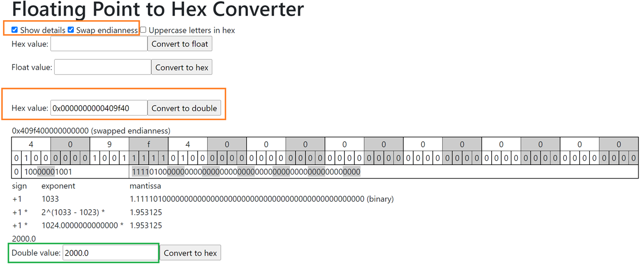
The return value is an 8 bytes double.
I used Greg Stoll's converter to verify this:

image: Greg Stoll's hex-to-double online analyser
You can now disconnect and close the demo. Next post is the LabVIEW USB init and teardown flow.
Related blog:


