element14 Community
element14 Community
    Register Log In
  • Site
  • Search
  • Log In Register
  • Community Hub
    Community Hub
    • What's New on element14
    • Feedback and Support
    • Benefits of Membership
    • Personal Blogs
    • Members Area
    • Achievement Levels
  • Learn
    Learn
    • Ask an Expert
    • eBooks
    • element14 presents
    • Learning Center
    • Tech Spotlight
    • STEM Academy
    • Webinars, Training and Events
    • Learning Groups
  • Technologies
    Technologies
    • 3D Printing
    • FPGA
    • Industrial Automation
    • Internet of Things
    • Power & Energy
    • Sensors
    • Technology Groups
  • Challenges & Projects
    Challenges & Projects
    • Design Challenges
    • element14 presents Projects
    • Project14
    • Arduino Projects
    • Raspberry Pi Projects
    • Project Groups
  • Products
    Products
    • Arduino
    • Avnet & Tria Boards Community
    • Dev Tools
    • Manufacturers
    • Multicomp Pro
    • Product Groups
    • Raspberry Pi
    • RoadTests & Reviews
  • About Us
  • Store
    Store
    • Visit Your Store
    • Choose another store...
      • Europe
      •  Austria (German)
      •  Belgium (Dutch, French)
      •  Bulgaria (Bulgarian)
      •  Czech Republic (Czech)
      •  Denmark (Danish)
      •  Estonia (Estonian)
      •  Finland (Finnish)
      •  France (French)
      •  Germany (German)
      •  Hungary (Hungarian)
      •  Ireland
      •  Israel
      •  Italy (Italian)
      •  Latvia (Latvian)
      •  
      •  Lithuania (Lithuanian)
      •  Netherlands (Dutch)
      •  Norway (Norwegian)
      •  Poland (Polish)
      •  Portugal (Portuguese)
      •  Romania (Romanian)
      •  Russia (Russian)
      •  Slovakia (Slovak)
      •  Slovenia (Slovenian)
      •  Spain (Spanish)
      •  Sweden (Swedish)
      •  Switzerland(German, French)
      •  Turkey (Turkish)
      •  United Kingdom
      • Asia Pacific
      •  Australia
      •  China
      •  Hong Kong
      •  India
      •  Korea (Korean)
      •  Malaysia
      •  New Zealand
      •  Philippines
      •  Singapore
      •  Taiwan
      •  Thailand (Thai)
      • Americas
      •  Brazil (Portuguese)
      •  Canada
      •  Mexico (Spanish)
      •  United States
      Can't find the country/region you're looking for? Visit our export site or find a local distributor.
  • Translate
  • Profile
  • Settings
Test & Tools
  • Technologies
  • More
Test & Tools
Forum Observing 96MHz clock signal and its divisions leads to "strange" results
  • Blog
  • Forum
  • Documents
  • Files
  • Members
  • Mentions
  • Sub-Groups
  • Tags
  • More
  • Cancel
  • New
Join Test & Tools to participate - click to join for free!
Actions
  • Share
  • More
  • Cancel
Forum Thread Details
  • Replies 21 replies
  • Subscribers 356 subscribers
  • Views 350 views
  • Users 0 members are here
  • multicomp pro oscilloscope
  • dso
  • oscilloscope
Related

Observing 96MHz clock signal and its divisions leads to "strange" results

obones
obones 9 days ago

Hello all,

I'm toying (pun intended) with ideas in the context of a future challenge and while I'm not settled on what the thing should do, I'm decided on using the MAX32666FTHR2 board that I was gifted with a couple of years back.

The "Light Up Your Life Challenge" gave me a push to finally use the 8*8 WS2812B matrix that I once bought because it looked nice and was not expensive, and so I'm trying to hook it up to the board.

As I can't seem to get the proper output signal to send to the LEDs, I decided to observe what's coming out of the MAX32666 pins.

My first experiment was to use a continuous timer, whose clock is half the system clock (96MHz) and which toggles the output pin every time the counter reaches the comparison value. Here is what I get with two relatively high values:

image image

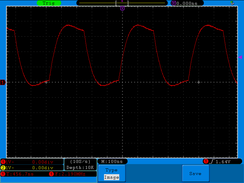
The signal should be a nice square wave, it does not look that clean, but I know there's always some rise and fall time coming into play.

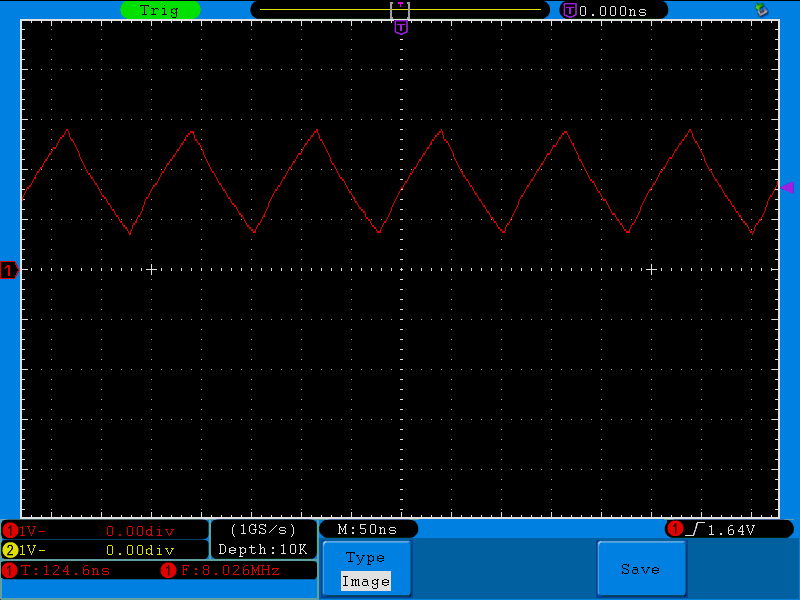
But things get worse when the comparison value for the timer is even lower, like here with 3:

image

After further fiddling with the various peripherals on the MCU, I was able to output the 96MHz clock signal, and this is what I get:

image

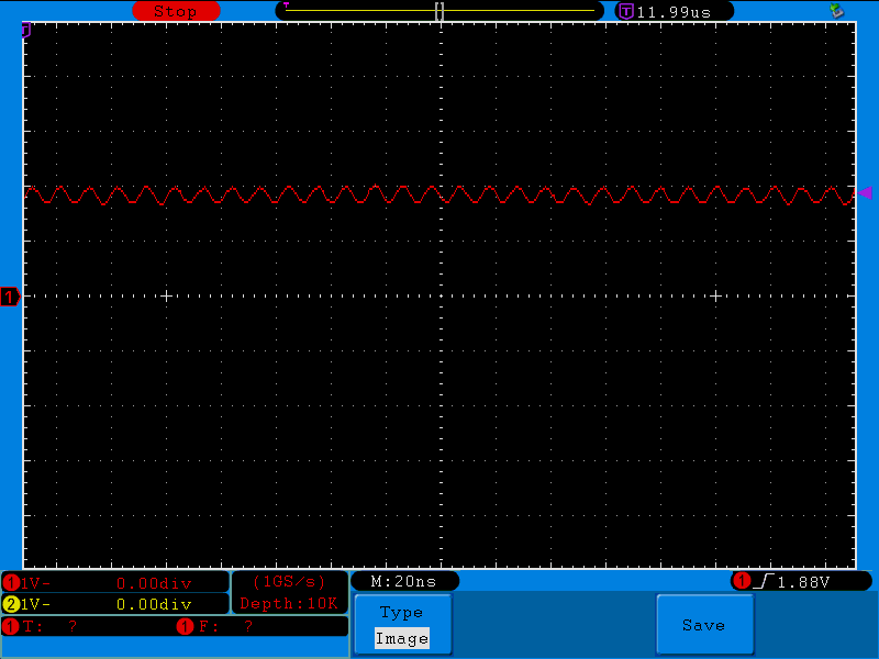
I had to stop the oscilloscope because it was not able to see a proper trigger level, let alone compute the frequency from such small signal.

Now, if I read the graph properly, there's about 10ns between two peaks, which is consistent with a 96MHz frequency for the signal.

However, what I'm really wondering about is the fact that the faster the signal, the more distorted I observe it, to the point where it won't even reach full voltage swing between 0V and 3.3V.

Out the top of my head, I can see three reasons for these results:

  1. Reaching the limits of the MAX32666 pin switching capabilities
  2. Reaching the limits of what the oscilloscope can see
  3. Reaching the limits of my own stupidity

For point 1, I tried looking for rise and fall time on output pins in the electrical characteristics for the MAX32666 but could not find anything related to this in the (somewhat confusing) datasheet.

For point 2, the DSO is said to be "100MHz" so as 96 is lower than 100, it should be fine. But maybe Shannon law should be taken into account and 100/2 being lower than 96, the results are expected.

For point 3, well, it could come on top of the two other points, and so I won't rule it out just yet.

I know there is a "Oscilloscope 101" webinar in the works which might actually answer those questions just fine. If that's the case, I'd gladly wait for it.

Thanks for your attention.

  • Sign in to reply
  • Cancel

Top Replies

  • Robert Peter Oakes
    Robert Peter Oakes 5 days ago +3
    one thing I did not see being mentioned is about the scope (And probes). Bandwidth of 100Mhz will be 3db down already but the reference for this is a sine wave, not a square wave. A square wave is made…
  • michaelkellett
    michaelkellett 9 days ago +1
    A (very) quick scan of the MAX32666 suggets that they have 4 possible drive current settings for GPIO pins. 1mA drive into a 10pF load will give you a slew rate of 100mV per ns. (and of course…
  • Jan Cumps
    Jan Cumps 7 days ago in reply to obones +1
    The oscilloscope has a 100 Mhz bandwidth. If you probe a 100 MHz square wave signal with it, you 'll notice a few things - even with perfect probing techniques The signal root wave (a 96 MHz sinus…
Parents
  • Gough Lui
    Gough Lui 9 days ago

    This is a clear sign of being slew-rate limited somewhere along the signal chain.

    You've mentioned your oscilloscope is "100MHz", but 96MHz is pretty close, so you can expect a slight amount of roll-off (up to 3dB) in your measurement already. This means about a halving of amplitude, but sometimes better.

    But have you checked the probes you're using are rated for 100MHz as well? I presume you'll be using "standard" 10:1 style passive probes, but they will have a rating - check in your probe manual. If your probes are cheap "50MHz" probes, well that could be your issue too.

    For the MAX32666 - how clean the output is really depends on the "load" on the pin (both resistive and capacitive). You may just have a scope probe on the pin - but scope probe impedance is a function of frequency. You can see this if you look at your scope probe manual - it will look something like this link. If your probe's loading graph looks like that, then you're basically loading your MAX32666's output pin with just 600 ohms, which could be a bit heavy but still perhaps acceptable. Usually heavier loads means logic voltages that are further from zero and VDDIO due to the internal resistances of the sourcing/sinking MOSFETs in the totem pole driver, resulting in lower voltage swing.

    Furthermore - are you using the "spring ground" or are you using a "ground clip"? Use of the "ground clip" lead is bad news for high frequency signals - it adds inductance and loop area causing "ringing" (i.e. ripples) that also affect the "squareness" and accuracy of overshoot/undershoot measurements. Shortening the ground return to the shortest length possible - i.e. using spring ground is definitely recommended for a clear image.

    - Gough

    • Cancel
    • Vote Up 0 Vote Down
    • Sign in to reply
    • Cancel
  • obones
    obones 8 days ago in reply to Gough Lui

    Thanks for your reply, here are some answers to your questions.

    The probes are the T5100 probes that came with the oscilloscope and are rated for 100MHz. Sadly, the manual does not have the graph you mentioned, only a voltage derating according to frequency graph.

    As to the "ground clip", I believe you mean the alligator clip small lead that attaches just below the guard as can bee seen here ?
    image

    If that's the thing, well, I did not hook it up to get the pictures above, and the situation did not change when I clawed it to a GND pin on the demo board.
    I searched for the term "spring ground" and saw various depictions of hand made metal springs that fit to the tip of the probe, but I can't seem to figure out if this would be applicable here.

    • Cancel
    • Vote Up 0 Vote Down
    • Sign in to reply
    • Cancel
Reply
  • obones
    obones 8 days ago in reply to Gough Lui

    Thanks for your reply, here are some answers to your questions.

    The probes are the T5100 probes that came with the oscilloscope and are rated for 100MHz. Sadly, the manual does not have the graph you mentioned, only a voltage derating according to frequency graph.

    As to the "ground clip", I believe you mean the alligator clip small lead that attaches just below the guard as can bee seen here ?
    image

    If that's the thing, well, I did not hook it up to get the pictures above, and the situation did not change when I clawed it to a GND pin on the demo board.
    I searched for the term "spring ground" and saw various depictions of hand made metal springs that fit to the tip of the probe, but I can't seem to figure out if this would be applicable here.

    • Cancel
    • Vote Up 0 Vote Down
    • Sign in to reply
    • Cancel
Children
  • Gough Lui
    Gough Lui 7 days ago in reply to obones

    Most oscilloscope probe bags have accessories including the spring ground - it should be fitted by removing the ground clip lead, removing the "hook" attachment and pushing over the coaxial ground contact collar which is around the probe tip as shown in the image at this link: https://electronics.stackexchange.com/questions/136123/how-do-you-attach-an-oscilloscope-ground-spring

    - Gough

    • Cancel
    • Vote Up 0 Vote Down
    • Sign in to reply
    • Cancel
  • obones
    obones 7 days ago in reply to Gough Lui

    Ah!
    So that's what this spring is about!
    I thought it was a spare for the spring inside the hook...

    • Cancel
    • Vote Up 0 Vote Down
    • Sign in to reply
    • Cancel
  • jc2048
    jc2048 6 days ago in reply to obones

    I quite often improvise 'springy clips', like this

    image

    That way, you can solder them, rather than hold the probe with one hand whilst working the controls with the other, though in this case it's quite precarious the way that I just have the tip touching the blob of solder (don't do that in the middle of a valuable board that you don't want to damage). The component between the blobs of solder is the SMD load resistor that I'm trying to probe as cleanly as possible. Sometimes, if I can be bothered, I'll do a little spiral for the probe tip to sit in which can also be soldered in place.

    My improvised ground clip was a lead offcut from a component (some old, cheap, but actually very good LEDs) and is plated steel rather than copper - copper is too soft and won't hold it's shape gripping the ground sleeve of the probe.

    If you want to see what I was doing with it, it's in the blog below; re-reading that, it's a right mess - I haven't explained what I was doing at all well. And I was wrong about the risetime. That was done with an old 200MHz Tek 2-series scope and the x10 passive probe that came with the scope, so the risetime you see in the waveforms is actually that of the scope and not the pin drivers on the Arduino Uno, nor the output of the transformer, which are both probably beating the scope, but it does show the clean results, without ringing, you can get in a low impedance circuit where the probe isn't loading it too much, and it does show how good the performance of a transmission-line pulse transformer can be, so not entirely wasted as a blog.

    https://community.element14.com/members-area/b/blog/posts/experimenting-with-a-transmission-line-transformer

    • Cancel
    • Vote Up +1 Vote Down
    • Sign in to reply
    • Cancel
element14 Community

element14 is the first online community specifically for engineers. Connect with your peers and get expert answers to your questions.

  • Members
  • Learn
  • Technologies
  • Challenges & Projects
  • Products
  • Store
  • About Us
  • Feedback & Support
  • FAQs
  • Terms of Use
  • Privacy Policy
  • Legal and Copyright Notices
  • Sitemap
  • Cookies

An Avnet Company © 2025 Premier Farnell Limited. All Rights Reserved.

Premier Farnell Ltd, registered in England and Wales (no 00876412), registered office: Farnell House, Forge Lane, Leeds LS12 2NE.

ICP 备案号 10220084.

Follow element14

  • X
  • Facebook
  • linkedin
  • YouTube