


I have been fascinated with Stirling engines ever since studying them in University. Although we got to measure performance of internal combustion engines in great detail, we only analyzed external combustion (Stirling cycle) engines theoretically. The PSoC6 Pioneer Kit makes it feasible to put together a capable instrumentation system to examine Stirling engine operation and performance. Working with a physical Stirling engine will be so much more interesting than just analyzing Carnot cycles. I have wanted to do this for decades, but the cost always seemed to put it out of reach. This project challenge came along at a moment in time when prices have come down on machines and powerful low-cost electronics are readily available, in fact the project is sponsoring some of the main modules I will be using. I will still have to buy a a lot of stuff for the project, but I am absolutely delighted to finally embark on this exploration of the mysterious workings of Stirling engines.
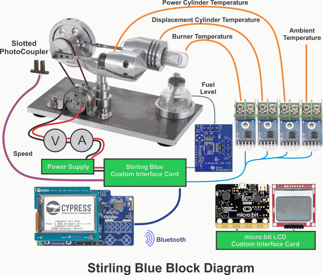
This project will not only explain how the engines work, it will measure and monitor every aspect of their operation. All sensors will be read by a PSoC6 which will calculate engineering units and display values on an E-Ink display, which will also explain the exhibit even when there is no power. All engine parameters will also be transmitted via Bluetooth low energy (BLE) to a Raspberry Pi and as a stretch goal to a BBC micro:bit.
The Stirling engine will run a generator which should produce enough power to run the instrumentation. The sensor system will monitor the entire power train - starting with the fuel consumption and ending with the electrical power generation - voltage and current.
The sensors will include:
- a capacitance sensor to measure volume of alcohol in the fuel tank
- an ambient temperature sensor
- a temperature sensor above the glass chamber over the flame
- a temperature sensor on the hot cylinder
- a temperature sensor on the cold cylinder
- a tachometer to measure flywheel speed
- generator speed will be calculated based on pulley ratio.
- a voltage sensor on the generator
- a current sensor on the generator output
- power generated will be calculated based on voltage and current.
The project idea is fairly simple, but the complete system will be fairly complex - the system is expected to include 19 circuit cards, 5 of which I will be designing. I will have to program the system using 3 different IDEs and 3 different programming languages. There will be at least 8 MCUs and at least 6 of them will have my code running on them. It is shaping up to be quite an exercise to design an aesthetic enclosure for all the electronics.
One pcb will manage power from the generator and interface all the sensors to the PSoC6.
Another PCB will add an LCD and FRAM chip to a BBC micro:bit. The FRAM chip is needed because the micro:bit does not have enough memory for LCD fonts.
The Raspberry Pi will have a 7” touch screen to display engine parameters.
It will be important to keep power consumption low as the generator will not produce much power.
The tachometer will most likely use a slotted photo coupler sensor, but if power becomes marginal, it may need to use a piezo sensor instead.
Since the temperature near the flame may be very high, thermocouples will be used to measure temperature.
Given the ornamental design of the Stirling engine, the electronics will be packaged cleanly in 3D printed housings.
It will be very interesting to see how well all these Bluetooth modules communicate especially with more than 2 devices in the mix.
If there is excess power available from the generator, I will connect a small fan to cool the cold cylinder – to see how it affects power output.
I will experiment with different structure around the burner to see if I can extract more power from the heat. I also want to try solar power to see if it will run off a Fresnel lens. The instrumentation should indicate how well each configuration works.
Monitoring all the different Stirling engine characteristics will provide much better insight into how these fascinating engines work and how to make them work better.
This project is going to turn an intriguing novelty engine into an informative educational demonstration as well as a showcase for interesting Bluetooth modules.
Upcoming blogs:
Blog 2 will be a quick unboxing and first programming exercise
Blog 3 will be about PCBs I am designing - these designs need to be completed early because I have been having a lot of difficulty getting reasonable delivery times
Blog 4 will be about how Stirling engines work
Related Links:
Bluetooth Unleashed Design Challenge
Bluetooth Unleashed Design Challenge: The Challengers
Bluetooth Unleashed Design Challenge: About This Challenge
Links to other blogs for this project:
Stirling Blue - Project Description - Blog 1
Stirling Blue - Unboxing Hero - Blog 2
Stirling Blue - micro:bit TXTR - Blog 3
Stirling Blue - Fuel Measurement - Blog 4
Stirling Blue - Interface Description - Blog 5
Stirling Blue - BBC micro:bit LCD - Blog 6
Stirling Blue - Power Measurement - Blog 7 (updated)
Stirling Blue - Bluetooth Terminal Awakening - Blog 8
Stirling Blue - PSoC Bluetooth Terminal Keyboard - Blog 9
Stirling Blue - Bluetooth Terminal - First Contact - Blog 10
Stirling Blue - micro:bit QWERTY keyboard & LCD - blog 11
Stirling Blue - TNT (Type-N-Text) - blog 12
Stirling Blue - TNT Ignition - Blog 13
Stirling Blue - Project Summary - Blog 14
Bluetooth Unleashed Design Challenge - Finisher Prize Unboxing - blog 15
Top Comments