Wildlife Monitor
Introduction
The purpose of this design challenge is to test the performance of a Hammond IP68 enclosure housing an electronic project in an extreme or harsh environment - "Experimenting with Extreme Environments".
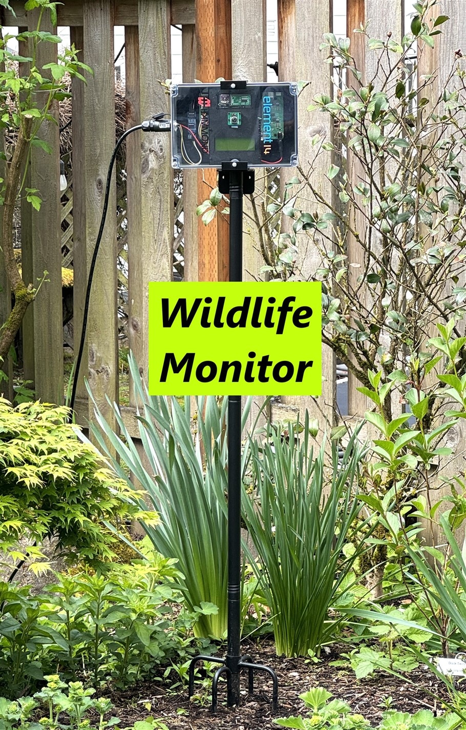
The inspiration for my project was a bifacial solar panel that I received as a Christmas present. The project is a solar powered wildlife monitor that can run standalone 24/7 outdoors. The weather in the Pacific Northwest (Oregon, USA) can present a reasonably extreme environment for an electronic enclosure. The project is being deployed from early May to late June and in the 30 years I've lived here I've experienced temperatures from 0-30 C and weather extremes of heavy rain and bright sunny days in that timeframe. Only nature will tell what we'll see. In the event that there isn't much rain, I'll do a hose spray test to verify the water integrity of the enclosure.
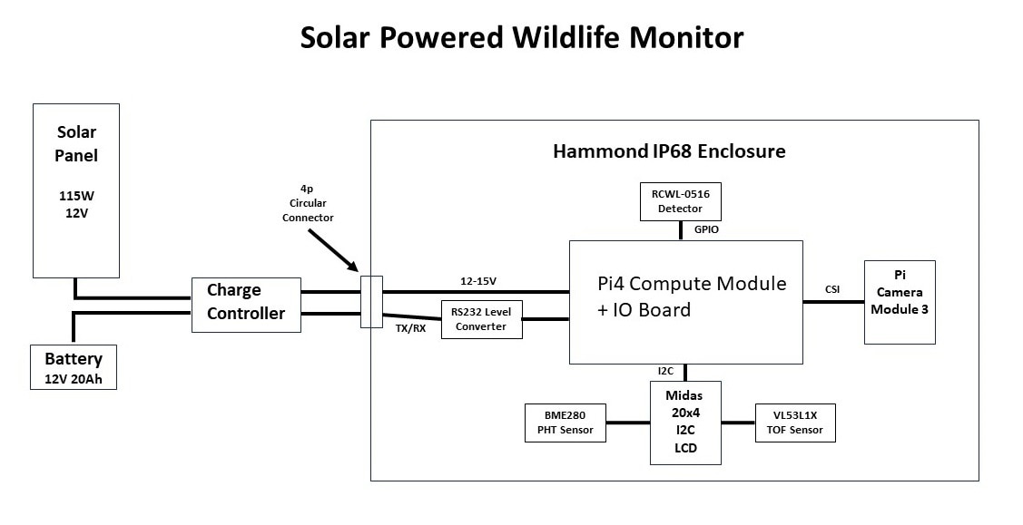
Project Block Diagram
Project Features
- Solar powered with battery backup
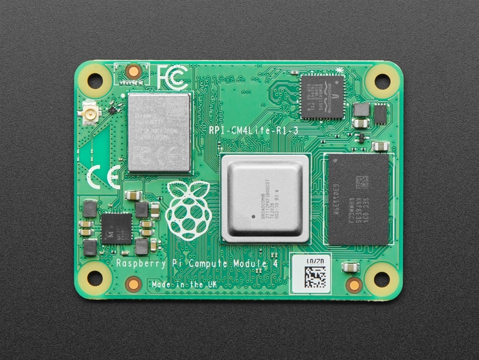
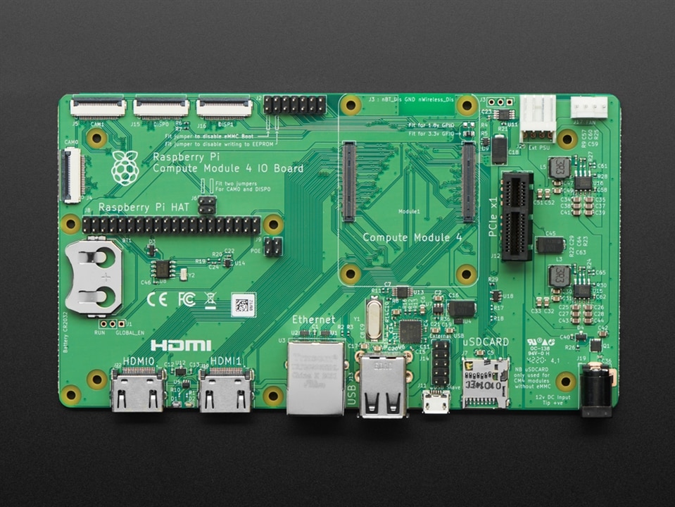
- Pi Compute Module 4 with IO Carrier board
- Pi Camera Module 3 with autofocus
- Solar charge controller with serial interface
- Microwave presence detector
- LIDAR time-of-flight sensor for proximity measurement
- Object detection using TensorFlow lite model
- Pressure/Humidity/Temperature sensor inside enclosure
- Weatherproof IP68 enclosure
- Status monitoring using MQTT and Node-Red
Overview
This is a description of the project from a functional level.
Power
The project is powered by the load output of the solar charge controller which is the switched battery voltage. The load output voltage will vary from 11V to 15V (nominally around 13V). The expected average load is under 10W so the 115W solar panel should be able to provide the required power during daylight even under cloudy conditions and the 240Wh battery can sustain it overnight and under dark conditions. The +12V barrel jack input on the CM4 IO board powers 2 onboard regulators, +5V for the CM4 and peripherals and +3.3V for PCIe. The barrel jack also feeds the +12V PCIe, the external PSU connector, and the fan connector. I am not using PCIe or powering external peripherals, so I should be okay according to the manual which indicates that the possible input range in that case is +7.5V to +28V. The onboard regulators are using AP64501 ICs which actually have a usable range of +3.8V to + 40V.
The manual recommends allowing about 9W of power for the CM4 and peripherals, but I'm hoping that on average that I can manage it well below that by limiting the frequency of higher power activities (WiFi, inferencing) and also powering down unused interfaces since I will be running headless over WiFi (e.g. HDMI, USB). The main concern here is the amount of heat generated within a sealed enclosure. I will definitely be adding a heatsink to the CM4 components. I'm primarily concerned about when the enclosure is in direct sunlight and there is a high ambient temperature.
Status Monitoring
I currently use MQTT and Node-Red servers to monitor and datalog my IoT projects.
Here is my measurement plan for this project:
- Solar charge controller - access through serial UART
- Controller Temperature
- Battery Voltage
- Battery Current
- Solar Panel Voltage
- Solar Panel Current
- Load Current
- RPi CM4
- CPU Temperature
- CPU Frequency
- BME280 inside enclosure
- Pressure
- Temperature
- Humidity
- Object Detection
- Detection Alerts
- Inference Results
- Captured Images
Wildlife Monitor
The objective of the wildlife monitor is to detect and identify wildlife (animals and humans) in my backyard and to capture and serve images of the object detected. Inferencing can consume a lot of power so I only want to run it when I've detected a moving object in view of the camera. Therefore I've set up a staged detection sequence listed below:
- Object detection sequence
- Movement detected (RCWL-0516 radar)
- Object in range (VL53L1X time-of-flight sensor)
- Inference result and confidence level (TensorFlow Lite model on CM4)
The microwave sensor has a broad detection range that I am going to try to limit to 6 meters and it is somewhat directional perpendicular to the component side of the PCB. It will generate an interrupt to a Python program to indicate there is movement in the general area. A TOF sensor will then determine when/if the object is within camera view/range. Then the program will publish the inference information and save the detected image.
I have some concerns about how well all this will work through the polycarbonate lid of the enclosure, so that's a risk.
I've tried running a simple TFLite object detection model on the RPi4 without the lid and that works well although with a low frame rate. I think the real trick will be to get the camera positioned properly relative to the lid. My main concerns with the lid are autofocus performance, TOF accuracy, image quality and reflections.
Enclosure Mount
I am going to mount the enclosure on a garden pole that had been used for a bird feeder. I 3D printed a frame that allows me to attach to the pole bracket and made some minor mods to the enclosure. More details and pictures later.
Parts List
Kit Parts provided
These parts were provided by Element14 and Hammond Manufacturing to be used in the challenge:
| Product Description | Datasheets |
|---|---|
| Pi4 Compute Module | Pi 4 Compute Module Datasheet |
| Pi4 Compute Module I/O Board | Pi 4 Compute Module I/O Board Datasheet |
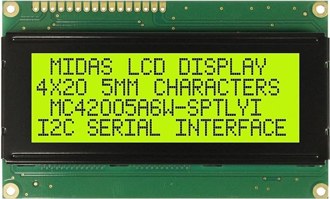
| Display, Alphanumeric, 20X4, I2C | Midas Display Datasheet |
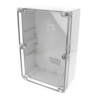
| IP68 Enclosure | Enclosure Manufacturer Page |
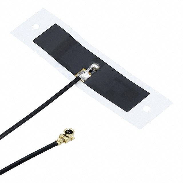
| RF Antenna, WiFi, BLE, Thread, Wireless Hart, Zigbee | Antenna Datasheet |
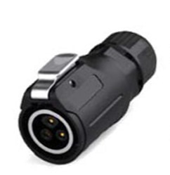
| Circular Connector, Cable Mount Plug, 4 Contacts | Connectors Datasheet |
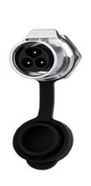
| Circular Connector, Panel Mount Receptacle, 4 Contacts |
| {gallery}Challenge Kit Parts |
|---|
|
Pi4 Compute Module (CM4) |
|
Pi4 Compute Module IO (CM4 IO) |
|
Midas Display, Alphanumeric, 20X4, I2C |
|
Hammond IP68 Enclosure |
|
RF Antenna, WiFi, BLE, Thread, Wireless Hart, Zigbee |
|
ICircular Connector, Panel Mount Receptacle, 4 Contacts (3 contact version shown) |
|
Circular Connector, Cable Mount Plug, 4 Contacts (3 contact version shown) |
Additional Parts
These are the parts that I added to complete the project:
| Product Description | Datasheets |
|---|---|
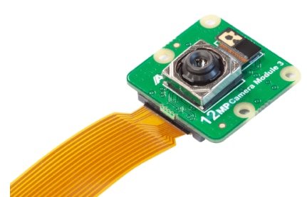
| RPi Camera Module 3 | Arducam RPi Camera Module 3 Datasheet |
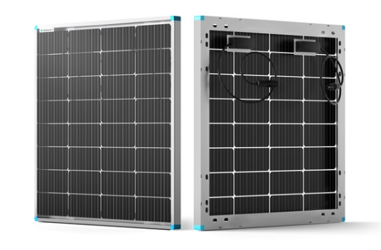
| Renogy 115W 12V Bifacial Solar Panel | Renogy 115W 12V Solar Panel Datasheet |
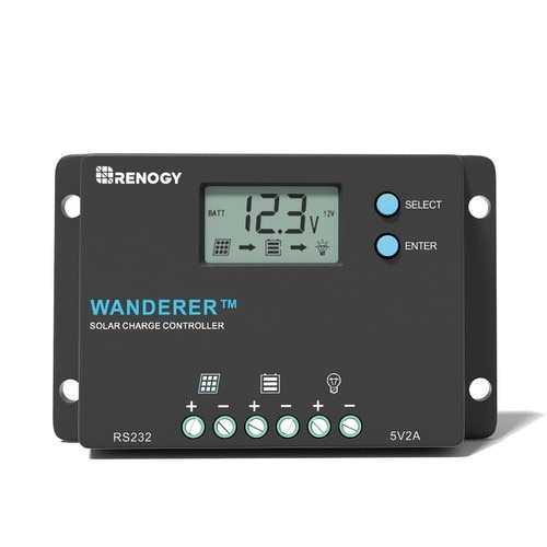
| Renogy 10 Amp 12V/24V Solar Charge Controller | Renogy Wanderer Charge Controller Datasheet |
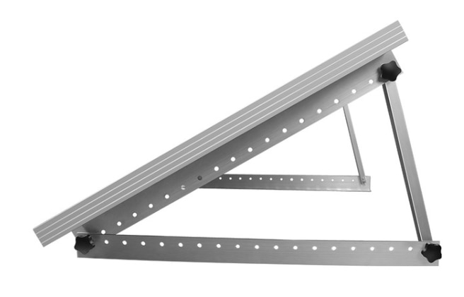
| Renogy Solar Panel Tilt Mount Brackets | Renogy Solar Panel Tilt Mount Bracket Specs |
| UPLUS 12V 20Ah AGM Battery | UPLUS LP12-20 12 Volt 20Ah Battery Product Link |
| TTL to RS232 Serial Level Converter | TTL to RS232 Level Converter Product Link |
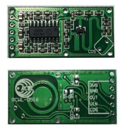
| RCWL-0516 3.2GHz Motion Detector | RCWL-0516 Github Project Link |
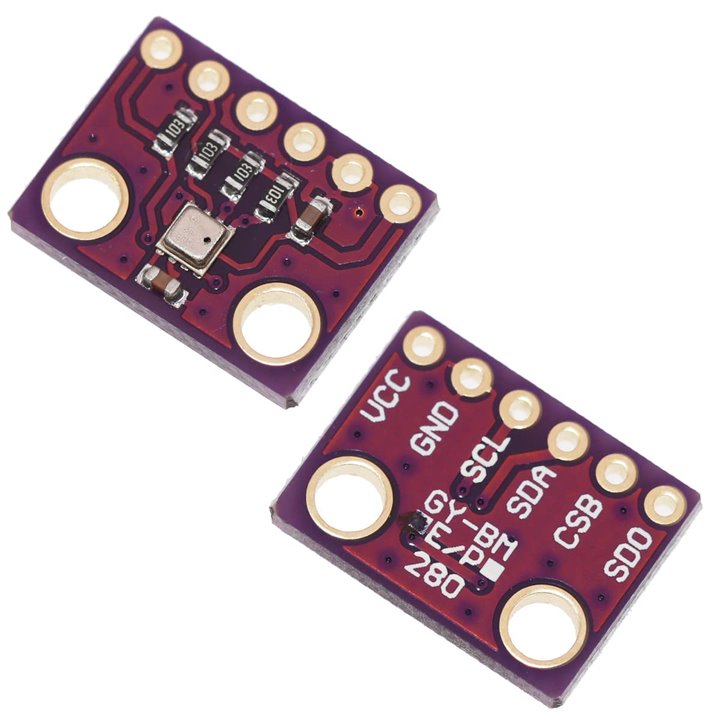
| BME280 PHT Sensor, I2C | BME280 Temperature Humidity Pressure Sensor Product Link |
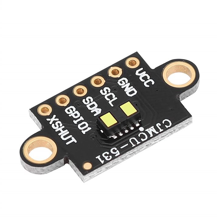
| VL53L1X TOF Distance Sensor, I2C | Vl53L1X Time of Flight Sensor Product Link |
| {gallery}Additional Parts |
|---|
|
RPi Camera Module 3 |
|
Renogy 115W 12V Bifacial Solar Panel |
|
Renogy 10 Amp 12V/24V Solar Charge Controller |
|
Renogy Solar Panel Tilt Mount Brackets |
|
UPLUS 12V 20Ah AGM Battery |
|
TTL to RS232 Serial Level Converter |
|
RCWL-0516 3.2GHz Motion Detector |
|
BME280 PHT Sensor, I2C |
|
VL53L1X TOF Distance Sensor, I2C |
Solar Panel Installation
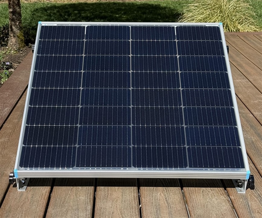
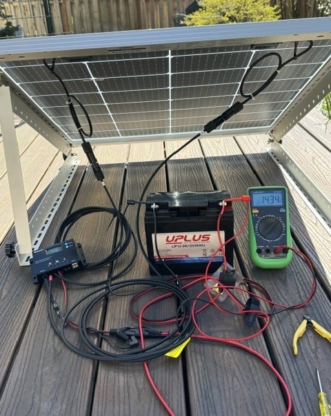
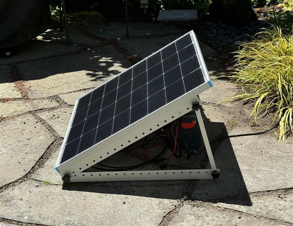
The project duration is mid spring to early summer so I've set the panels up with a south facing orientation and a 30 degree inclination from horizontal. I did a quick test of the panel charging the battery through the charge controller.
A quick video of the charge controller sequencing through its status displays.
Displaying
- Solar Panel Voltage
- Solar Panel Current
- Battery Voltage
- Battery Current
- Controller Load Mode - 15 means that it requires manual turn on
- Load is off so there is no Load Voltage/Current displayed
The panel module on my stone patio. The power cable to the enclosure is exiting to the right.
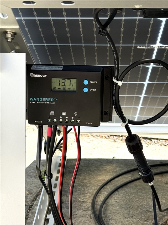
The solar module needs some work to provide a water resistant housing for the charge controller which is currently just mounted under the panel. My temporary solution is to attach shield panels to the mounting rails.
Enclosure Design
The following parts were 3D printed to mount components in the enclosure and to attach the enclosure to the garden pole:
- Baseplate to mount the CM4 IO and RS-232 level converter board to the floor of the enclosure
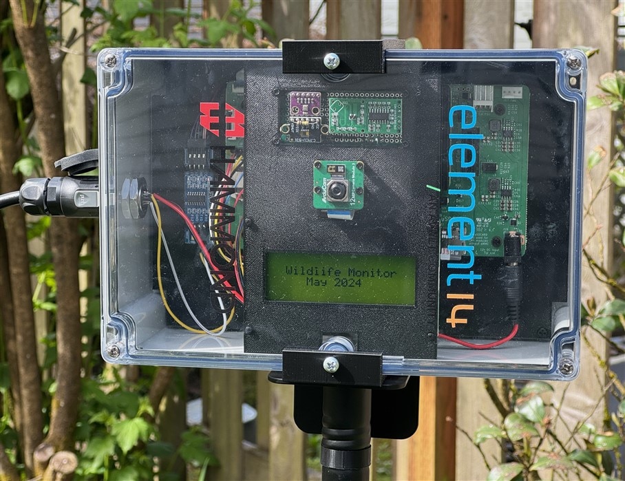
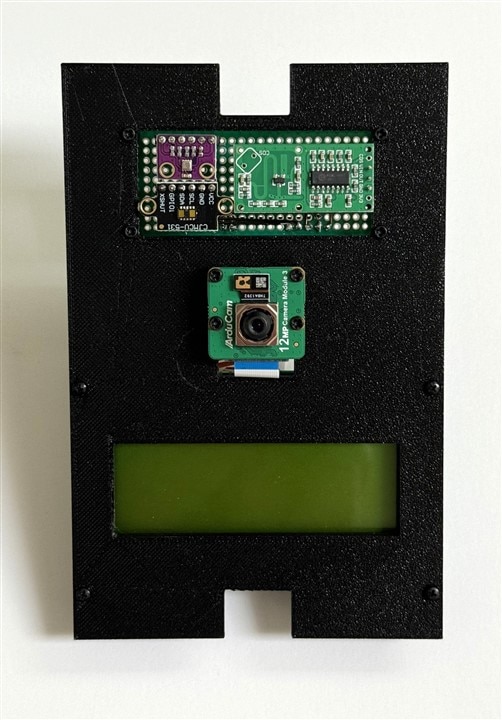
- Front panel to mount the sensors, Pi Camera, and Midas display at the top of the enclosure near the lid
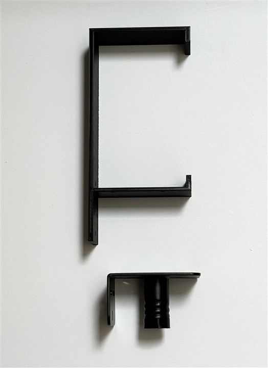
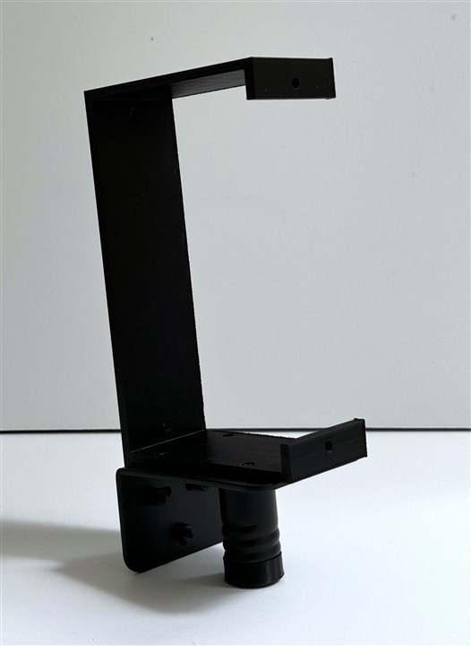
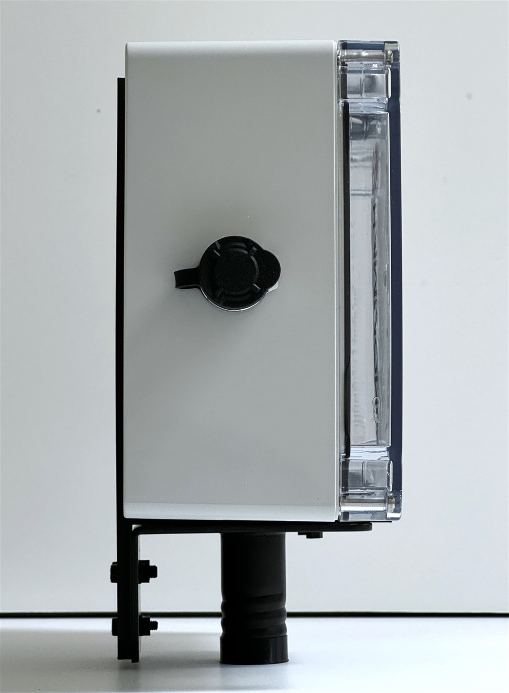
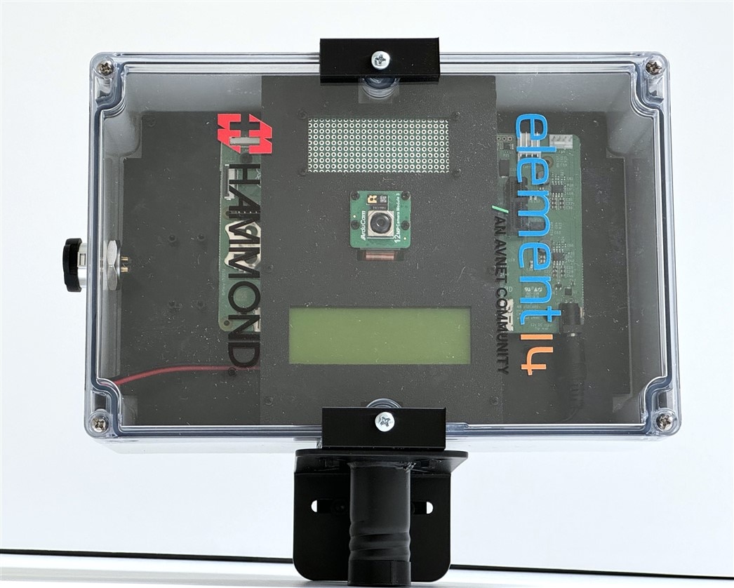
- External Pole Mounting Bracket Adapter to attach enclosure to garden pole
- Rear Plugs to attach Bracket Adapter to rear of enclosure
Baseplate
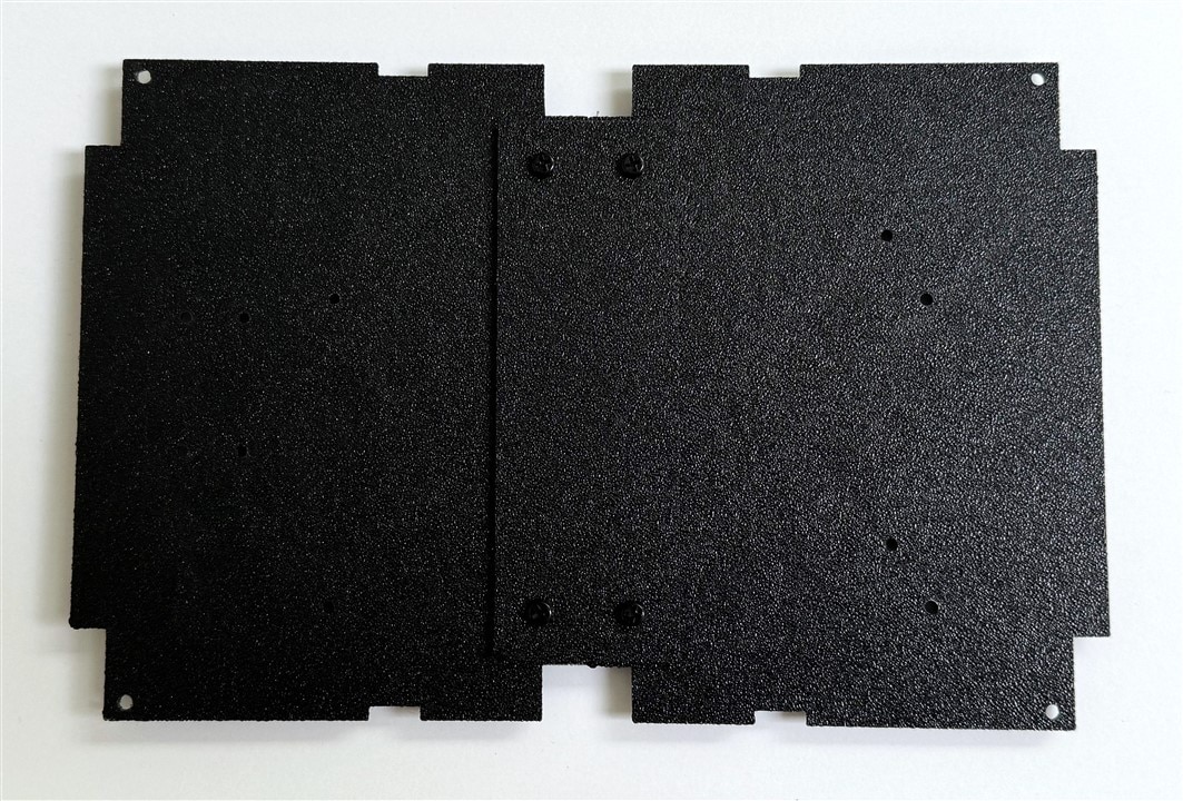
The required dimensions (226mm x 147mm) of the baseplate exceed the printable area on my Anycubic Kobra 2 so I needed to print the baseplate in two halves and add a plate to join the two halves together.
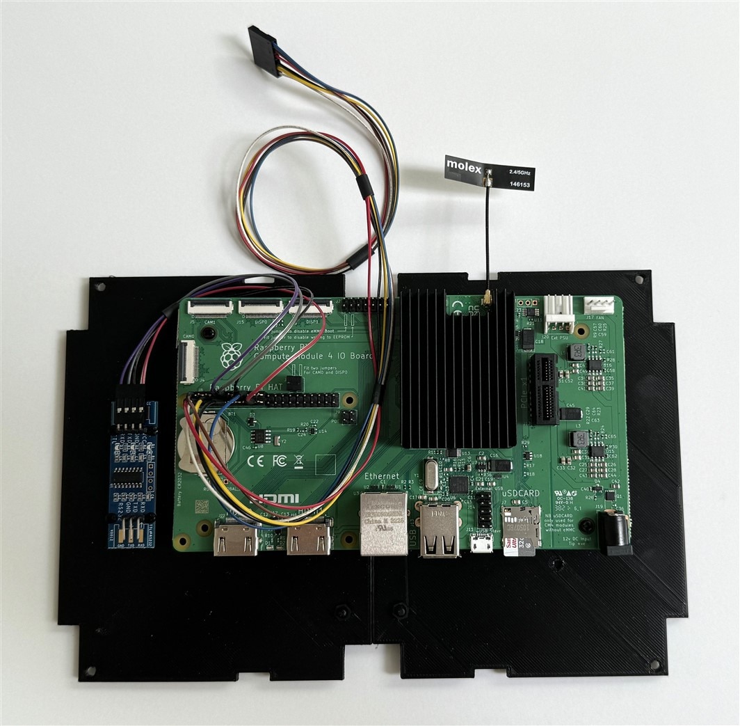
The CM4 IO board is attached to the baseplate using 4 M2.5 standoffs. The position of the CM4 IO board is offset to allow mounting the RS-232 level translator on the left and allowing space for the power barrel plug cable at the bottom right. The bottom space also allows insertion and removal of the uSD card. Luckily, I am not using most of the connectors and just need access to the GPIO header on the left above the RTC battery and the CSI connector on the upper left (I'll need to leave the CSI cable attached unless I dismount the board). The photo below shows the CM4 module mounted on the CM4 IO board with heatsink and WiFi antenna attached. The GPIO cables to the RS-232 level translator and the front panel are also shown.
Front Panel
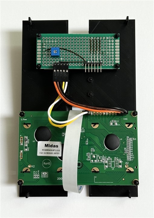
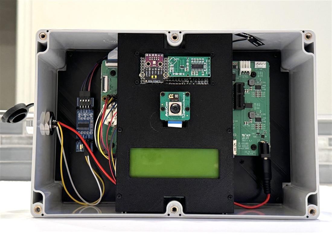
The Front Panel holds the sensors, camera, and 4x20 character display at the top center of the enclosure. The BME280, VL53L1X, and RCWL-0516 are mounted on a protoboard at the top of the panel. In the rear view of the panel, the left connector interfaces the I2C, power, and contrast adjustment potentiometer to the Midas Display. The right connector interfaces I2C, power, and the RCWL-0516 output to the CM4 IO GPIO connector via the wire harness shown in the photo above.

Interconnect
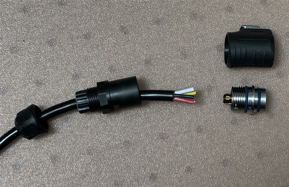
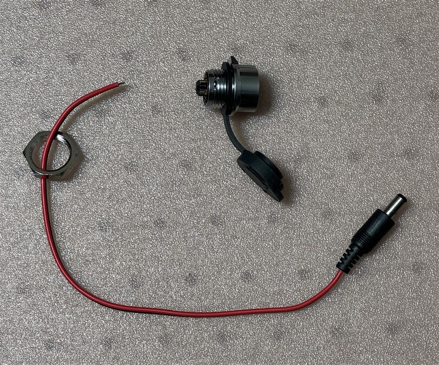
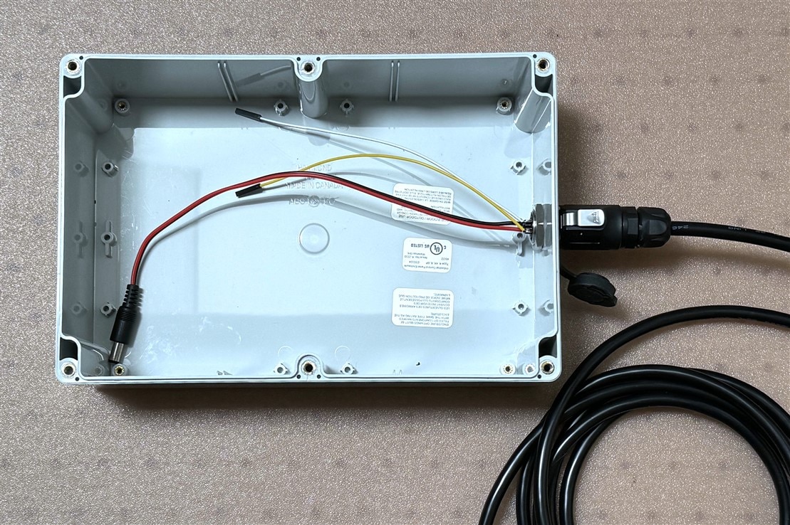
The external interconnect to the enclosure is straightforward as there are only 4 pins involved that connect via the Amphenol 4 pin circular connector pair. The external cable carries the +Load Voltage, Ground, Tx, and Rx signals from the Charge Controller. Internally the +Load Voltage and Ground connect to a 2.1mm barrel plug that delivers power to the CM4 IO board. The Tx and Rx signals connect to the Rx and Tx inputs of the RS-232 level shifter. The Ground for the level shifter is common to the CM4 IO through the GPIO wiring harness. The completed wiring is shown in the bottom photo.
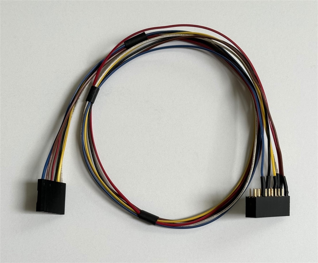
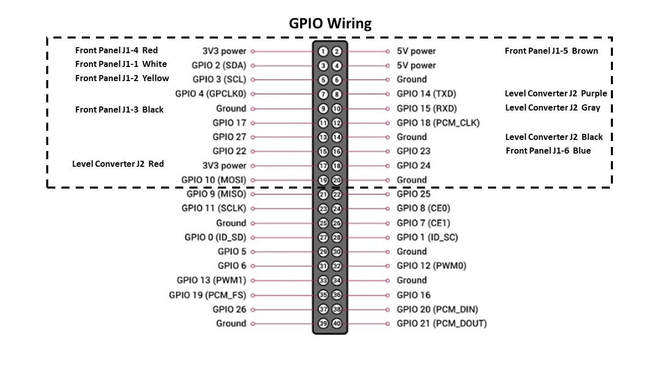
I had initially prototyped GPIO connections using individual single wire jumpers, but realized that it would be complicated to connect and disconnect boards. I decided it would be better to build a wire harness using a 20 pin socket header that I could plug down onto the GPIO pins and wire to two separate connectors for the Front Panel and the RS-232 level shifter. Unfortunately, I only took a photo of the the assembly with the Front Panel connector before I added the RS-232 connector. The completed harness is shown in the earlier Baseplate assembly photo.
Below is the pin diagram of the harness:
The photo below is the completed enclosure assembly.
Pole Mounting Hardware
I needed a method to attach the enclosure to the mounting bracket of the garden pole so I 3D printed a bracket that attaches to the enclosure that uses 4 screws along the centerline - 2 front cover screws and 2 corresponding screws in the back using threaded inserts. Photos below show the attachment assembly.
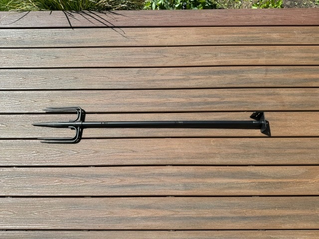
This is the garden pole that I am using. The 5 prong base mechanism is very stable and the height is adjustable by adding or removing 16 inch threaded sections.
Software Development
Operating System
I am using the latest Raspberry Pi OS which is based on Debian 12 (Bookworm). I started out using an RPi4 for software development and migrated that firmware/software to the CM4 mounted on the CM4 IO carrier board. The CM4 module that is used in this project had 4GB of RAM, WiFi, and no eMMC, so when paired with the CM4 IO it booted and operated from the uSD card just as an RPi4. As a matter of fact, I used the same uSD card in both configurations and only required minor device tree tweaks to the /boot/firmware/config.txt file to enable CM4 IO hardware features that aren't on the RPi4 (RTC, second camera).
I have the system set up in headless configuration interfaced over WiFi:
- Hostname "wildlifepi"
- Static ipaddr
- SSH and VNC enabled
- I2C, UART, and RTC enabled
Here is my /boot/firmware/config.txt which shows what is enabled and the device tree modifications:
# For more options and information see
# http://rptl.io/configtxt
# Some settings may impact device functionality. See link above for details

# Uncomment some or all of these to enable the optional hardware interfaces
dtparam=i2c_arm=on
#dtparam=i2s=on
dtparam=spi=on

# Enable audio (loads snd_bcm2835)
dtparam=audio=on

# Additional overlays and parameters are documented
# /boot/firmware/overlays/README

# Automatically load overlays for detected cameras
camera_auto_detect=0

# Automatically load overlays for detected DSI displays
display_auto_detect=1

# Automatically load initramfs files, if found
auto_initramfs=1

# Enable DRM VC4 V3D driver
dtoverlay=vc4-kms-v3d
max_framebuffers=2

# Don't have the firmware create an initial video= setting in cmdline.txt.
# Use the kernel's default instead.
disable_fw_kms_setup=1

# Run in 64-bit mode
arm_64bit=1

# Disable compensation for displays with overscan
disable_overscan=1

# Run as fast as firmware / board allows
arm_boost=1

[cm4]
# Enable host mode on the 2711 built-in XHCI USB controller.
# This line should be removed if the legacy DWC2 controller is required
# (e.g. for USB device mode) or if USB support is not required.
otg_mode=1

[all]

enable_uart=1
dtoverlay=imx708
dtoverlay=imx219,cam0
dtoverlay=i2c-rtc,pcf85063a,i2c_csi_dsi
The biggest surprise for me was the paradigm change in Bookworm to enforce a split in package installation between site-wide packages which are installed with APT and Python packages which are installed with PIP. I resolved the issue by installing the python3-virtualenv package and managing the virtual environment in the Thonny editor.
Remote Application Interfaces used
VNC
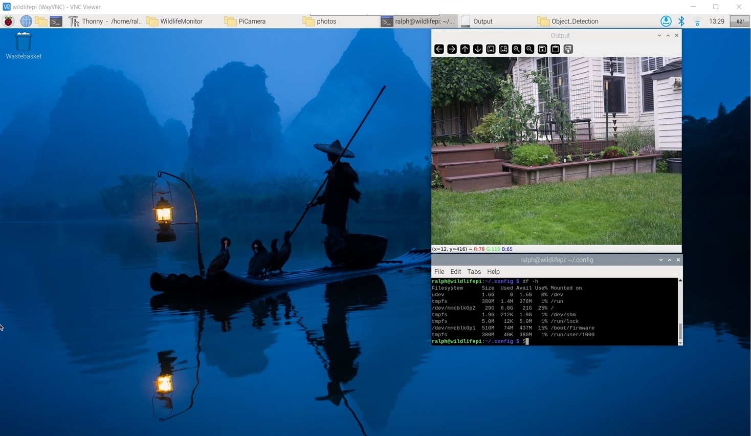
It's convenient to have a remote graphical interface for development and also for documenting projects. The RPi OS image includes VNC so I am using that. Bookworm has switched to using the WayVNC server, but I've continued to use RealVNC for my WIndows PC client. The only configuration setting that I needed to change was the default window size as it was coming up as 1280x720. It took some searching to discover that the default output when running headless is NOOP-1.
In the ~/.config/wayfire.ini file I added the output definition at the end:
[output:NOOP-1]
mode = 1920x1080@60000
position = 0,0
transform = normal
scale = 1.000000
PuTTy
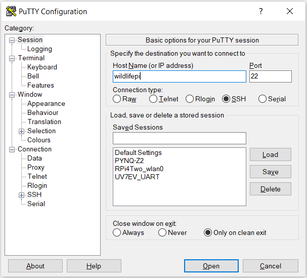
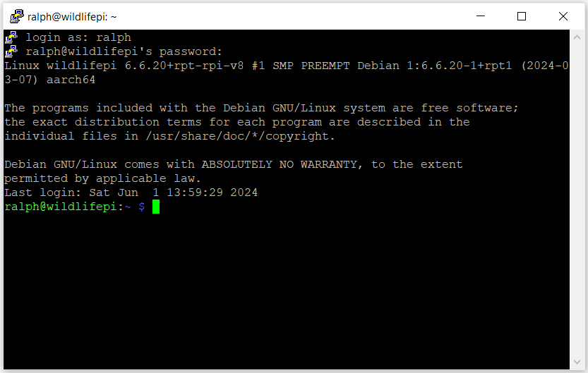
I use PuTTy as the remote SSH terminal when I don't need a graphical interface. For this project I relied mainly on VNC and used the terminal within VNC for command line interface.
WinSCP
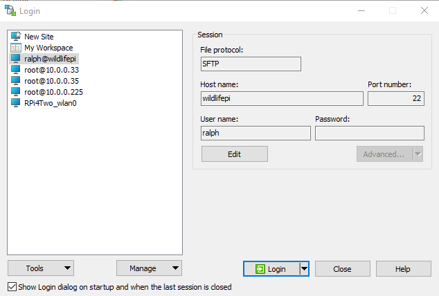
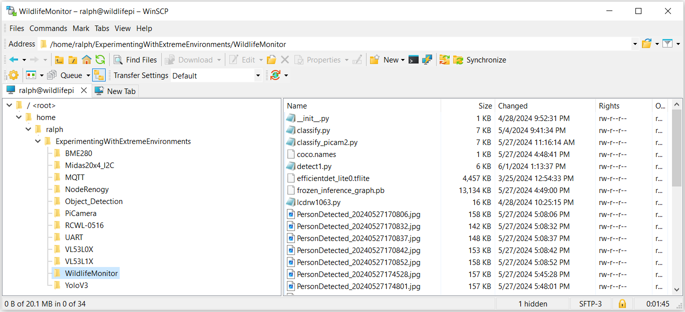
I use WinSCP for remote file transfers to/from the RPi and my WIndows file systems using the SFTP protocol. It opens the remote file system in a familiar interface and provides convenient drag and drop file transfers.
PHP Web Gallery
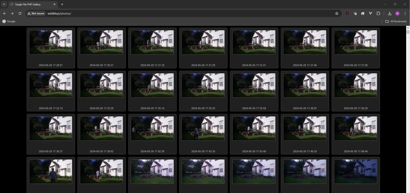
Since I am going to be saving lots of camera images I wanted to enable a Web based image gallery that I could bring up remotely in a browser.
To start I needed to install the Apache2 web server and PHP. There is a good tutorial at this link: https://www.tomshardware.com/news/raspberry-pi-web-server,40174.html.
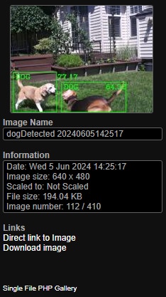
Then I installed the Single File PHP Gallery. As the name suggests there is a single PHP script that you can copy into any directory to create a web image gallery. Clean and simple. Then I just need to save my images in that directory or a sub-directory.
An image from my Object_Detection directory that was downloaded from the browser.
And there is also a nice info panel that lists image details.
Monitor Application Operation
During the process of project implementation and deployment outdoors I encountered problems that required changes to the hardware and software that are described below. First I'll describe the issues and the changes that I made then I'll describe the final software configuration and test results.
Implementation issues and required changes
- LIDAR ToF sensor did not work through the transparent enclosure lid
- Camera image was blurred through the transparent enclosure lid.
Both issues that I encountered were related to the transparency of the polycarbonate enclosure lid. The lid is probably not intended for use with cameras or optical sensors. The LIDAR sensor is using an infrared diode and the lid appears to block transmission of that light frequency. The sensor worked fine without the lid up to 4-5 meters. The sensor did not work at all when I installed the lid. I had initially mounted the sensor so that it was about 1 cm away from the lid. I tried moving the sensor to within 1 mm of separation and that actually got the sensor to have reasonable readings within 200-300 mm but it failed to detect beyond that. I did not do a lot of testing or documentation but I think that I'll try testing the sensor behind different types of glass and plastic in the future. I decided that I would give up on the staged detection feature and just use the microwave radar sensor to directly trigger an object detection inference operation. The microwave sensor works fine through the lid so the only liability is that because it has more range and field of view (FOV) than the camera that there will be more false inference triggers that could have been filtered out using the LIDAR.
A quick illustration using some empirical data to figure out the FOV of the microwave sensor (region that generates motion triggers).:
FOV of microwave sensor
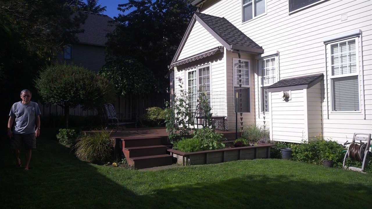
FOV of camera

The second issue with the lid was the blurring of the camera image. I initially thought that it might have been an issue with the autofocus but manually focusing the camera did not help. I took a close look at the lid and there appear to be "striations" in the lid material - possibly caused by the manufacturing process. I have to admit that I didn't notice it initially as it's not real obvious until you look at it from the side with light reflecting off it.
I tried to get a clear picture of it but couldn't get a good focus using my iPhone. The lid doesn't appear this blurry but I couldn't get the striations in focus from this side angle where they are more visible.

It is very obvious in the camera images with the lid and without:
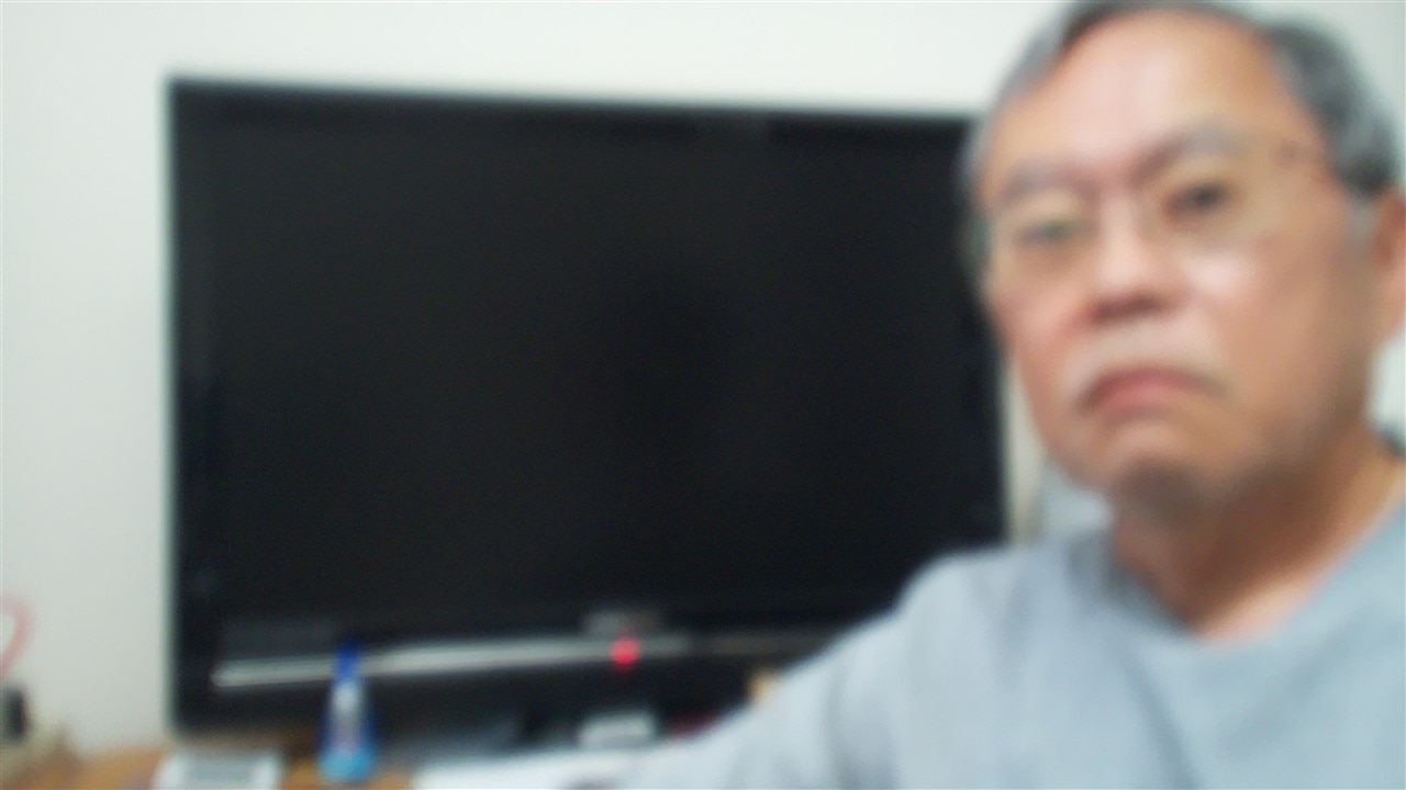

It turns out that we used the same Hammond enclosure for the Waterproof Connectors challenge and the lid from that enclosure didn't have this issue. That lid had some surface scuffs from use but one of the two possible lid orientations worked with where the camera is mounted. Quite a stroke of luck! There is still some image degradation but it's much better.
Final software configuration
I have a number of variants of the monitor application for testing. The version I'm using for deployment uses the microwave motion trigger to run object detection. It will save one or two images - the first is always saved on motion detection and the second is only saved if the inference returns a result. The second will show the bounding box, class detected and confidence. The detection threshold is 0.6.

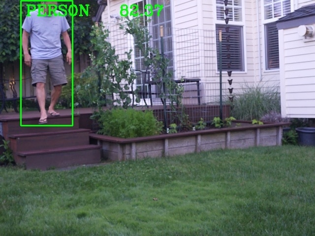
I also have versions that run continuously with and without saving images to test processor performance and thermal issues. The model that I ended up using is "ssd_mobilenet_v3_large_coco_2020_01_14".
The program listing is below:
wmMotionInferenceSensors.py
import cv2
import os
import Sensors
import schedule
from picamera2 import Picamera2
from gpiozero import DigitalInputDevice
from datetime import datetime
from time import sleep

picam2 = Picamera2()
#camera_config = picam2.create_still_configuration(main={"size": (1920, 1080)}, lores={"size": (640, 480)}, display="lores")
#picam2.configure(camera_config)
picam2.configure(picam2.create_preview_configuration(main={"format": 'XRGB8888', "size": (640, 480)}))

radar = DigitalInputDevice(23, pull_up=False, bounce_time=2.0)

#picam2.start_preview(Preview.QT)
picam2.start()
sleep(2)

#This is to pull the information about what each object is called
classNames = []
classFile = "coco.names"
with open(classFile,"rt") as f:
    classNames = f.read().rstrip("\n").split("\n")

# Classes to ignore
ignore_classes = ["backpack", "bench", "car", "chair", "clock", "frisbee", "motorcycle", "potted plant", "skateboard", "umbrella"]  # Add the classes you want to ignore here

#This is to pull the information about what each object should look like
configPath = "ssd_mobilenet_v3_large_coco_2020_01_14.pbtxt"
weightsPath = "frozen_inference_graph.pb"

#This is some set up values to get good results
net = cv2.dnn_DetectionModel(weightsPath,configPath)
net.setInputSize(320,320)
net.setInputScale(1.0/ 127.5)
net.setInputMean((127.5, 127.5, 127.5))
net.setInputSwapRB(True)

#This is to set up what the drawn box size/colour is and the font/size/colour of the name tag and confidence label
def getObjects(img, thres, nms, draw=True, objects=[]):
    classIds, confs, bbox = net.detect(img,confThreshold=thres,nmsThreshold=nms)
#Below has been commented out, if you want to print each sighting of an object to the console you can uncomment below
#print(classIds,bbox)
    if len(objects) == 0: objects = classNames
    objectInfo =[]
    if len(classIds) != 0:
        for classId, confidence,box in zip(classIds.flatten(),confs.flatten(),bbox):
            className = classNames[classId - 1]
            if className in objects and className not in ignore_classes:
                objectInfo.append([box,className])
                if (draw):
                    cv2.rectangle(img,box,color=(0,255,0),thickness=2)
                    cv2.putText(img,classNames[classId-1].upper(),(box[0]+10,box[1]+30),
                    cv2.FONT_HERSHEY_COMPLEX,1,(0,255,0),2)
                    cv2.putText(img,str(round(confidence*100,2)),(box[0]+200,box[1]+30),
                    cv2.FONT_HERSHEY_COMPLEX,1,(0,255,0),2)

    return img,objectInfo

def mdetected():
    timestamp = str((datetime.now()))
    timestamp = timestamp[0:19]
    print("Motion detected at", timestamp)
    picam2.capture_file('/var/www/html/photos/motion_detected/%s.jpg' % timestamp)
    # GET AN IMAGE from Pi camera
    img = picam2.capture_array("main")
    img = cv2.cvtColor(img, cv2.COLOR_BGRA2BGR)
    #Below provides a huge amount of controll. the 0.45 number is the threshold number, the 0.2 number is the nms number)
    result, objectInfo = getObjects(img,0.6,0.2)
    if len(objectInfo) != 0:
        timestamp = datetime.now().strftime("%Y%m%d%H%M%S")
        image_name = f"/var/www/html/photos/motion_detected/{objectInfo[0][1]}Detected_{timestamp}.jpg"
        cv2.imwrite(image_name,img)

if __name__ == "__main__":
    radar.when_activated = mdetected
    schedule.every(1).minutes.do(Sensors.program)

    while True:
        schedule.run_pending()
        sleep(1)

        k = cv2.waitKey(200)
        if k == 27:    # Esc key to stop
            # EXIT
            picam2.stop()
            #picam2.stop_preview()
            cv2.destroyAllWindows()
            #display.lcd_clear_display()
            break
In addition to standard python libraries, there are two custom libraries used
- lcdrw1063.py - written by javagoza to interface with the Midas display
- Sensors.py - an auxiliary module that I wrote to publish sensor data via MQTT
Sensors.py
import paho.mqtt.publish as publish
from subprocess import check_output
from re import findall
import schedule
from time import sleep
from gpiozero import Button
from datetime import datetime
import lcdrw1063 as LCD
from signal import pause
import bme280
import smbus2
import os

port = 1
address = 0x76 # Adafruit BME280 address. Other BME280s may be different
bus = smbus2.SMBus(port)

bme280.load_calibration_params(bus,address)

display = LCD.Lcd()

def get_temp():
    temp = check_output(["vcgencmd","measure_temp"]).decode("UTF-8")
    return(findall(r"\d+\.\d+",temp)[0])

def get_core_clock_speed():
    output = check_output("vcgencmd measure_clock arm", shell=True)
    core_clock_speed_hz = int(output.decode().split("=")[1].strip())
    core_clock_speed_ghz = "{:.3f}".format(core_clock_speed_hz / 10**9)
    return core_clock_speed_ghz

def publish_message(topic, message):
    print("Publishing to MQTT topic: " + topic)
    print("Message: " + message)
    publish.single(topic, message, hostname="10.0.0.234")

def program():
    cpu_temp = get_temp()
    cpu_freq = get_core_clock_speed()
    bme280_data = bme280.sample(bus,address)
    box_humid  = "{:.1f}".format(bme280_data.humidity)
    box_press  = "{:.1f}".format(bme280_data.pressure)
    box_temp = "{:.1f}".format(bme280_data.temperature)
    publish_message("WildlifeMonitor/cpu_temp", cpu_temp)
    buffer = " CPU Temp: " + cpu_temp + " C"
    display.lcd_display_string(buffer, 2)
    publish_message("WildlifeMonitor/cpu_freq", cpu_freq)
    publish_message("WildlifeMonitor/box_temp", box_temp)
    buffer = " Box Temp: " + box_temp + " C"
    display.lcd_display_string(buffer, 3)
    publish_message("WildlifeMonitor/box_humid", box_humid)
    publish_message("WildlifeMonitor/box_press", box_press)

if __name__ == "__main__":
    schedule.every(1).minutes.do(program)

    while True:
        schedule.run_pending()
        sleep(1)
Python packages installed
- opencv-python - for cv2
- mediapipe - auxiliary support for cv2
- picamera2 - interface with rpi camera and cv2
- gpiozero - DigitalInputDevice is used as the interrupt input for the microwave sensor digital output
- schedule - periodically publish sensor data
Node-Renogy - this is a helper program written using Node.js by someone at Renogy to publish the solar charge controller data via MQTT. This program runs separately in the background.
Node-Red Dashboard - running on a separate RPi4 server on my local network to display MQTT data
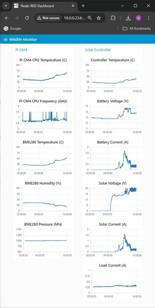
Enclosure Thermal Performance
A major concern as always with electronics in a sealed enclosure is heat, especially with a higher power module like the CM4 which could dissipate over 10 W. From data I've taken so far I don't expect to exceed an average of 5 W and with active mitigation I think I could stay in the range of 2 - 2 1/2 W (my current setup idles at around 1.4 W). But we occasionally get ambient temperatures above 40 C and and I currently have the enclosure out in the open exposed to full sun, so I thought I should get a baseline.
For my first test I'm going to run continuous inferencing with data publishing every minute as this should be the max power for this application.
This data was taken on June 6, 2024, the high temperature was 28 C and the low was 13 C. I wanted to see if the CPU would reach throttling temperature (80 C) under these conditions. System power consumption was around 4 W.
The part of the chart in the yellow box is the time that the enclosure is in full sun. The ambient temperature increased about 10 C in that time so it appears that the additional 10 C is due to sun exposure.
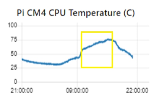
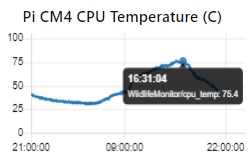
The CPU hit a max temperature of 75.4 C so there was about 5 C of margin before throttling. As we get into summer, both the ambient temperature and length of sun exposure will increase so throttling will occur. Most of this change is driven externally so I doubt that reducing the power will be enough to fix it. The obvious solution here is to put the enclosure in some shade.
If I have time and can find an equivalent day, I'll run the test using triggered inference and increasing the data publishing interval (10 min?).
Solar Module Performance
The solar setup should be capable of continuous supporting a 10-15 W load during the winter when days are much shorter and we have a lot fewer sunny days. We are almost to the longest day of the year so I didn't anticipate any issues but it's good to verify that the setup is operating as expected.
The spec value on the solar panel is 115 W but that is under standard test conditions (25 C ambient, 1000 W/m2, perpendicular incident angle). On mid-day on a sunny day I should be able to get 100 W from the panel. My total continuous load running with a motion trigger is 3 W x 24 hrs = 72 Wh/day. So, I can get that capacity in less than 1 hour. Of course, on a rainy day in the winter it might be challenging to get that capacity in the whole day.
The battery capacity is 12 V @ 20 Ah = 240 Wh. Without recharge a 3 W load should run for 80 hrs so there's lots of margin. Looking at historical data for my location, the panel would probably average 550 Wh/day in June and 150 Wh/day in December so a 10 W (240 Wh/day) load would be okay in the summer but would require another panel in the winter.
What does a typical early summer day look like? Here's the data from June 8.
Sunrise was 05:22 and sunset was 20:57. It was partly cloudy to sunny and the temperature was 15 - 28 C.
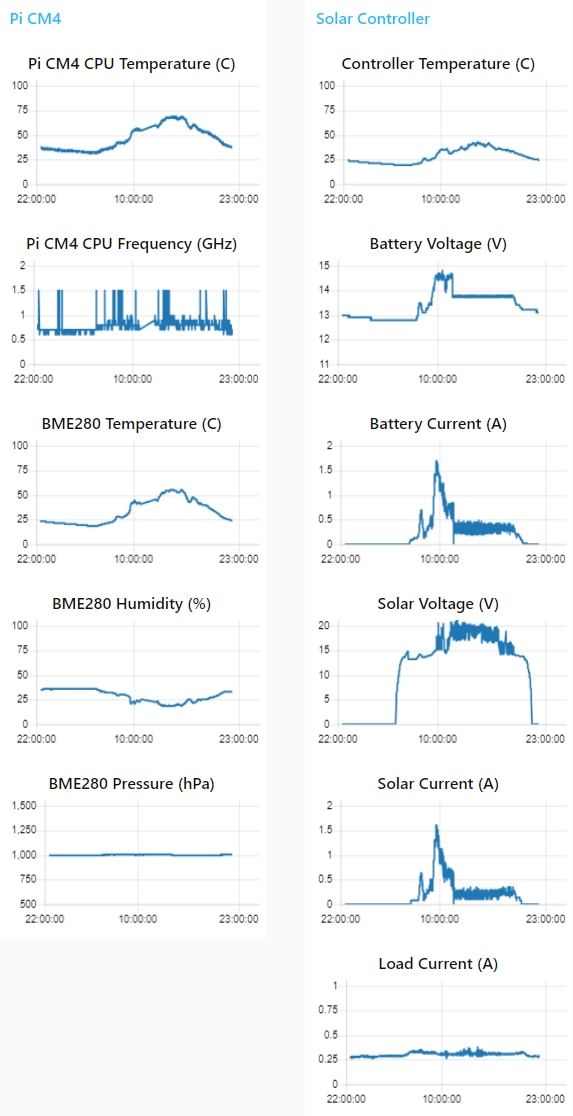
From the CPU Frequency plot I can tell that I'm running in motion trigger mode. Most of the time the processor clock is at 700 or 800 MHz. Most all of the spikes to 1.5 GHz are caused when inferences are run. A similar plot in continuous inference mode will be at 1.5 GHz almost 100 % of the time. Also the Load Current will be 100 - 150 mA higher with continuous inference.
The Solar Voltage shows that the panel is generating voltage from about 30 minutes before sunrise to about 30 minutes after sunset. The smoother parts at the shoulders of the curve are the regions where the panel does not have sufficient power to charge the battery.
The step up in Battery Voltage and Solar Current indicate that the panel is charging the battery and supporting the load. When the battery voltage steps back down the battery is maintaining charge and the panel is supporting the load.
In the sections where the Solar Voltage and Current have lots of "hair" the charge controller is managing the maximum power point (MPPT).
I'm not sure if the Battery Current is a redundant sensor (it has its own register) because it only tracks current into the battery charger which is equivalent to the solar current. The battery plot has a slightly higher value (due to lower voltage) but I may just remove it to conserve dashboard space.
The Load Current is reasonably constant. It is somewhat higher when the panel is on. It doesn't track the changes in battery voltage (which is also the load voltage), so I'm not sure what causes that. Wish I had a schematic.
The controller seems to be working as I expected.
There is a parameter named Battery Capacity that should indicate how much longer the battery will maintain 12V but I'm not sure how that is calculated on this controller. AGM batteries have a very consistent discharge curve so it could just be a function of the output voltage.
I didn't plot the capacity parameter but here is a capture of the status output at midnight after the battery had been discharging for about 3 1/2 hours.
![]()
The battery discharged to 82 % Battery Capacity before there was enough solar energy in the morning to start recharging. If that is accurate then it lost 18 % capacity in 10 hours which would mean that it would take 56 hours to fully discharge. A bit less than my 80 hour estimate but still lots of margin.
Object Detection Performance
The model that I'm using is a general purpose object detection model. It includes 91 classes of which 1 is person and 10 others are animals.
The 10 animal classes are:
- bird
- cat
- dog
- horse
- sheep
- cow
- elephant
- bear
- zebra
- giraffe
Not a good representation of backyard wildlife, but sufficient for proof of concept. As a future improvement I should use transfer learning using this model with more appropriate images to retrain a better model.
So, how did this model perform?
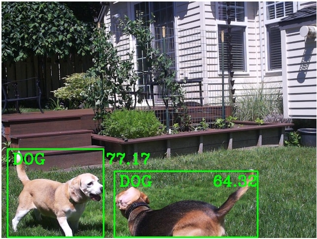
The average inference time was 250 ms. This is the same speed that I achieved with the TFLite 'efficientdet_lite0.tflite' model I had prototyped with on the RPi4. The accuracy felt qualitatively better, but I had run that model indoors vs my current outdoor setup. I have the confidence level threshold set at 60%.
Person
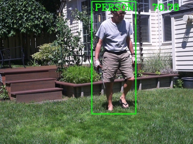
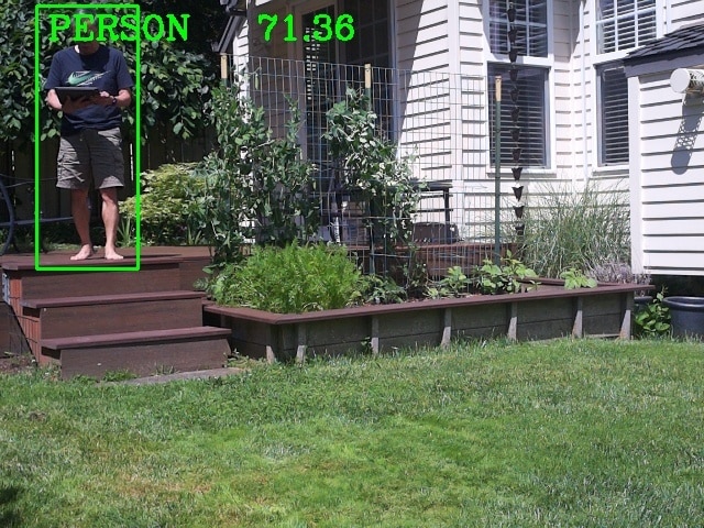
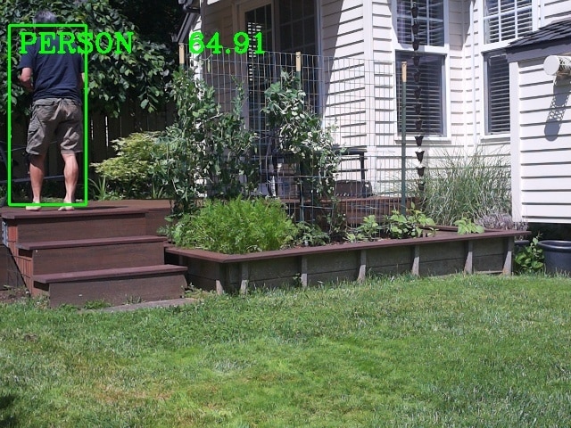
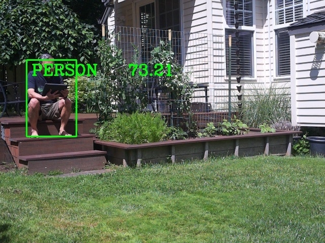
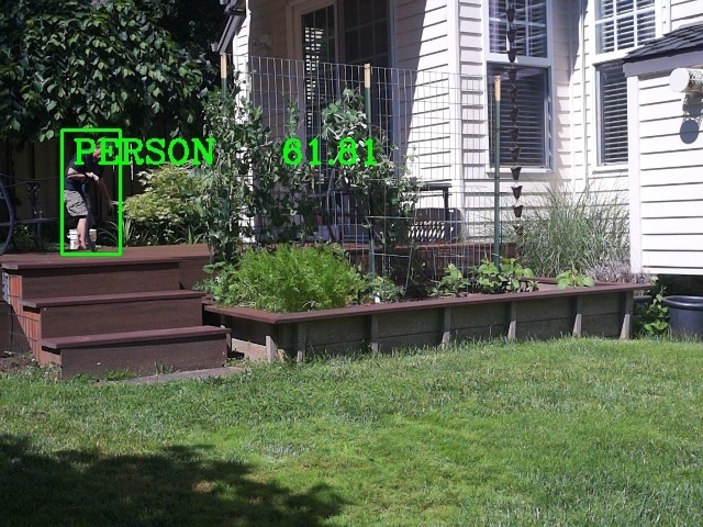
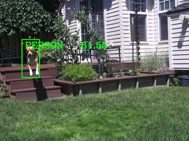
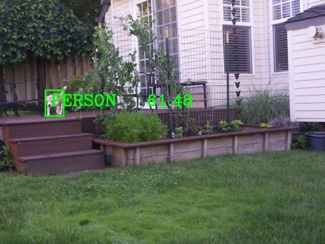
It does well identifying a person as a person - different views, sizes, lighting, partial images. Does not seem to misidentify a person as another class. It will misidentify another class as a person when the image size is small. Here's a sample of different identifications:
Dog
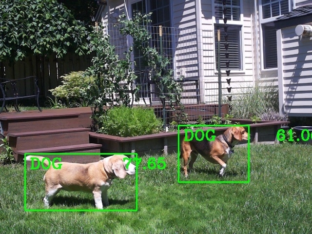
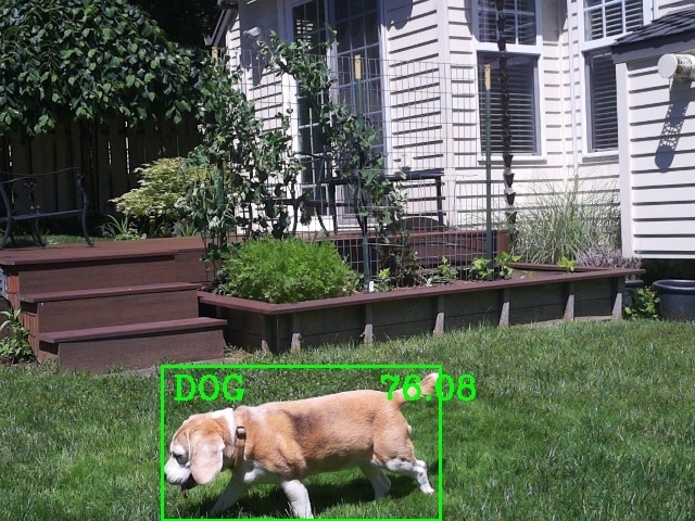
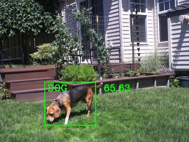
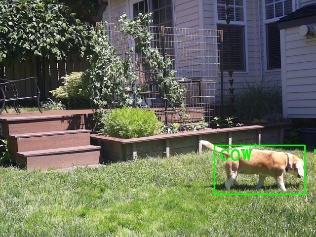
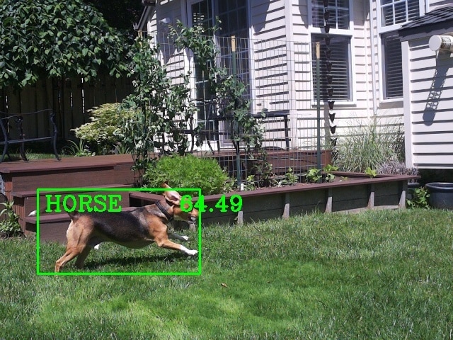
I have two granddogs , both tri-color Beagles. The older dog is smaller and has lighter coloration. The younger one is larger with longer legs and has darker coloration. I think the coloration versus the training dataset confuses the model's ability to identify them as dogs vs a horse or a cow. The lighting, image size, and partial image are more of a problem than for a person.
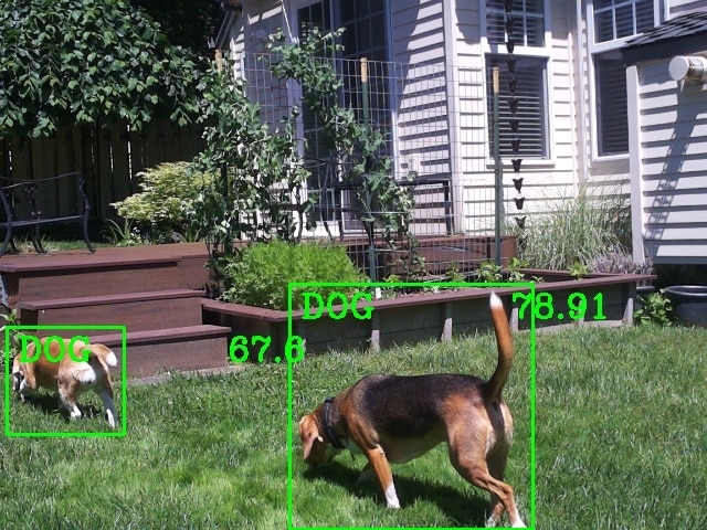
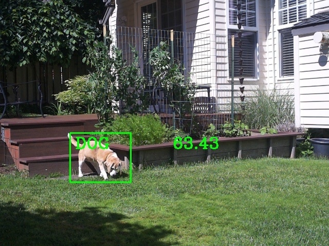
Multiple classes
The model was built with the COCO (Common Objects in Context) dataset which is a large-scale image recognition dataset for object detection, segmentation, and captioning tasks built using over 330,000 images, each annotated with 80 object categories and 5 captions describing the scene. It does well identifying multiple different classes in an image as long as the objects don't significantly overlap.
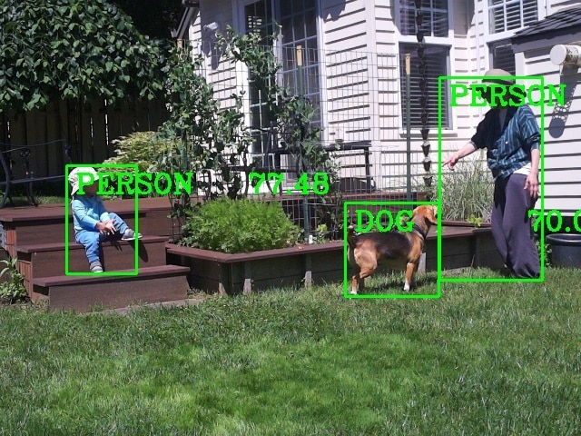
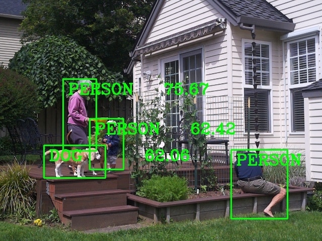
Misclassifications
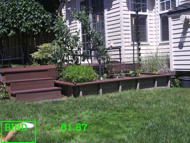
This is like the "blooper" reel. Even with the confidence set at 60% objects get misclassified a lot, especially in poor lighting (low light, glare, shadows, etc.), with small image sizes, and partial object images in the detection frame. Also, in the case of the dogs - color is probably not well represented in the training dataset.
Tip of dog's tail misclassified as a bird
Dog misclassified as a cow
Dog misclassified as a horse
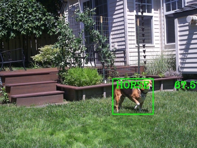
Dog misclassified as a person
Some object detection video
Dog Detection (1/2 speed)
Environmental Testing
I had the project fail after multiple weeks of continuous operation. There were a few warmer days and I was testing to see if the processor would get to the throttling point while running continuous inferencing. Unfortunately, it failed in the early afternoon and I did not realize that it had failed until I checked the data that evening. Data from the monitor stopped after about 15:40. The CPU temperature had peaked at 78.4 C and at last report was 77.5 C. The processor clock was still at 1.5 GHz so no throttling. When I checked the setup, communication was not working. I could not establish a WiFi connection and without access to the module I couldn't determine what state it was in. The red power LED was on and the green ACT LED would light periodically which seemed to indicate there was some SD card access. I checked the local charge controller display and verified that battery voltage was good. The load current was slightly above idle but lower than it would be if the monitor program was running.
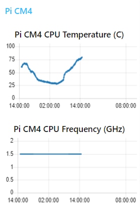
I switched off the load at the charge controller then switched it back on after a minute to reboot the CM4 and everything recovered. Not sure what caused things to hang up. We'll have to see if it happens again.
Finally a couple of days of rain. Unfortunately, just light rain during the early morning so not much to show. Guess I'll need to do a hose spray test. One effect of the cloudier days is that the Battery Capacity got down to 80%.
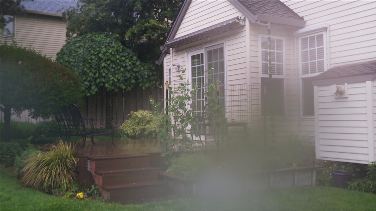
As I was about to do the hose test dark clouds moved in and there were rain showers accompanied by wind gusts. The showers seemed reasonably heavy but after I viewed the video I decided that I should do the hose test anyway.
Rain showers
Video showing the rain and wind gusts.
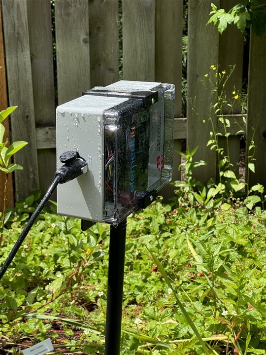
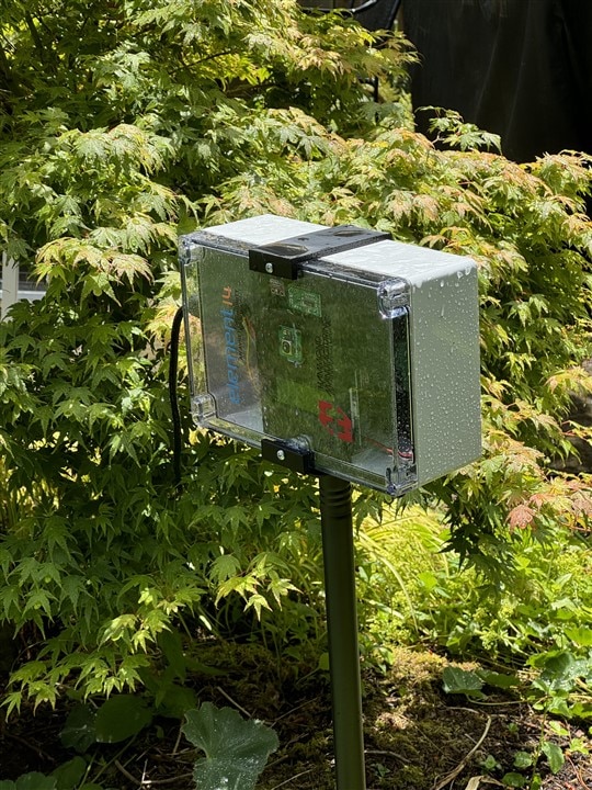
Pictures of enclosure after rain stopped.
Hose Spray
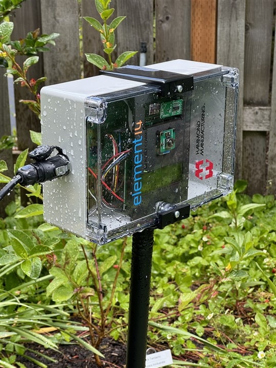
Video of me spraying enclosure with the garden hose with the shower setting on the nozzle. I directed the spray at the cover seams and and the connector mounting. No water incursion as expected. It could still classify me as a person through the spray.
Picture of enclosure after spray stopped.
Summary
Overall, another very satisfying challenge experience. Thanks to Element14 and Hammond for sponsoring the challenge and providing the challenge hardware. As usual I learned lots of new things, got to use new (to me) hardware, and had fun. The weather ended up not being as challenging as it has in the past despite threats of an "atmospheric river" expected early this month that was supposed to deliver as much rain in one day as we would normally see all month. That never occurred - I was hoping to get good video and ended up with just a constant drizzle.
Drizzle just leaves water on the lid
Even the temperature has been fairly moderate with a low of 5 C and a high of 32 C for this period. So not much short term stress but the sun exposure will be a severe test over time. The Hammond enclosure was watertight as expected. It's great that they provide customized cutouts for connectors to ensure a good fit.
My biggest disappointment so far has been the lack of wildlife detected. We usually get our share of normal suburban wildlife - birds, squirrels, rabbits, cats, rats, mice, and an occasional racoon. We do get coyotes and deer also, but so far not in my backyard. And normally they are on or under the deck or in the vegetable garden (right in view of the camera). So, what have I seen so far? Just a couple of birds in the yard in front of the garden.
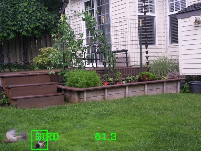
So, I guess I'll just have to keep waiting...
Project Extra Credit Blogs
These blogs provide more detailed descriptions of the build process and software installation and operation.
| Blog 1 - Introduction | |
| Blog 2 - Unboxing and Parts Description | |
| Blog 3 - Enclosure Modification | |
| Blog 4 - Software Development | |
| Blog 5 - Project Integration |




Top Comments
-

genebren
-
Cancel
-
Vote Up
0
Vote Down
-
-
Sign in to reply
-
More
-
Cancel
Comment-

genebren
-
Cancel
-
Vote Up
0
Vote Down
-
-
Sign in to reply
-
More
-
Cancel
Children