


Table of Contents
- Crafting the Magic Lightbox Prototype: From Concept to Foam Board Reality
- Magic Lightbox High Level Design
- Magic Lightbox Dimmable LED Driver Prototype Schematics
- Magic Lightbox Use Cases
- Magic Lightbox Test Mockup Construction
- Unit Testing the Lightbox. It Turns On and Lights Up.
- Manual dimmer. Changing the duty cycle with a rotary encoder
- Prototype Firmware for the Magic Lightbox
- Testing Prototype Firmware for the Magic Lightbox. Simulation mode
- Magic Lightbox Blog Series
Crafting the Magic Lightbox Prototype: From Concept to Foam Board Reality
As we reach the culmination of our adventure, it's time to bring the Magic Lightbox to life with our first prototype. In this blog, we'll consolidate all our learnings to design the prototype schematic and embark on the construction of our first model using foam board.

Magic Lightbox High Level Design
The Magic Lightbox system comprises:
- A chassis
- Two LED Lamps
- One Arduino microcontroller
- One microcontroller with camera sensor
- Adjustable Switched Mode Flyback Converter Using Analog-to-Digital Current Feedback
Magic Lightbox High-Level Circuit Diagram
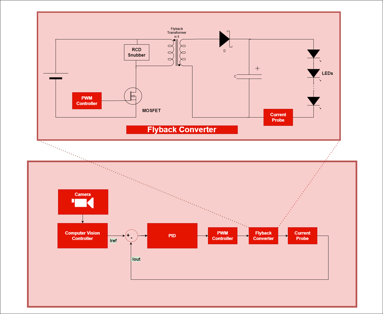
Explanation of the Diagram:
PID Controller: The PID controller regulates a closed-loop system to reach the desired output state. It consists of three elements providing Proportional, Integral, and Derivative actions. The PID controller calculates the difference between actual and desired current, adjusting based on current error, past errors, and future error predictions.
PWM Controller: Pulse Width Modulation (PWM) modifies the duty cycle of a periodic signal, controlling the energy stored in the Flyback transformer.
Flyback Converter: A DC-to-DC converter with galvanic isolation between input and output. When activated, the primary coil connects to the power source, increasing magnetic flux in the core. The secondary voltage is negative, keeping the diode blocked. Power to the load comes from the output capacitor. When the switch is open, energy stored in the core transfers to the LEDs and the output capacitor.
Current Probe: Measures current without direct series connection. Converts current to voltage for measurement using an analog-to-digital converter.
Computer Vision Controller: Analyzes image contrast and suggests a target current value for the PID controller.
Camera: Captures light, converting it into an electrical signal processed to form a digital image.
Magic Lightbox Dimmable LED Driver Prototype Schematics
This the electronic circuit governing our dimmable LED panel.

Let's delve into its key sections:
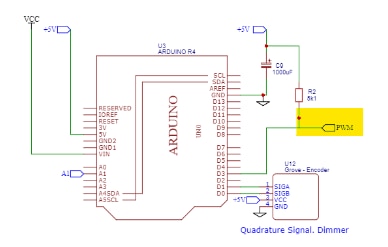
Section 1: Arduino R4 PWM Signal Generation
At the heart of the system is an Arduino R4 responsible for generating the PWM signal that regulates the MOSFET's on-off cycles. This PWM signal is intentionally inverted, passing through an inverter to safeguard the Arduino's output PIN, which supports a limited current of 8 mA. There is a pull-up resistor for when the Arduino output port is in an unstable or undefined state.
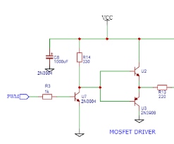
Section 2: NPN Inverter and Totem-Pole MOSFET Driver
The inverted PWM signal flows into an NPN Transistor inverter. The output goes to new stage comprising two complementary transistors (NPN-PNP pair) in a totem-pole configuration. This setup provides the required current and voltage for the MOSFET switching.
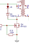
Section 3: MOSFET Protection with Voltage Clamp
Ensuring the MOSFET's longevity and reliability, a protective voltage clamp is implemented. This feature shields the MOSFET from potential voltage spikes that could arise during operation. The clamp consists of a fast diode and a Zener diode, effectively limiting voltage peaks and safeguarding the MOSFET against damage.
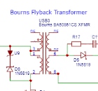
Section 4: Bourns BA60951CS Flyback Transformer
The Bourns BA60951CS Flyback Transformer takes center stage. This transformer stores energy as magnetic flux when the MOSFET switches to the "on" position and subsequently releases that energy to the transformer's secondary circuit when it switches to "off".

Section 5: Secondary Diode
On the secondary side, a fast diode plays a pivotal role. This diode prevents the flow of current when the MOSFET switch is in the "on" position but permits it when the MOSFET switch transitions to "off." At this moment, the primary inductance, charged during the "on" cycle, acts as a generator, contributing to a continuous flow of energy. An RC snubber network protects the diode.

Section 6: Secondary: Filter Capacitor
On the secondary side, a filtering capacitor charges and acts as an "electricity pump" for the load.
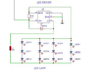
Section 7:LED Driver and Load
The load consists of 12 LEDs grouped into 4 sets of three LEDs, all controlled by an LED Driver. The LED driver is a CL6807 LED driver.
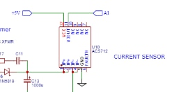
Section 8: Current Sensing Probe
In this section, a dedicated current sensing probe plays a crucial role. It generates a voltage signal that mirrors the magnitude of the current flowing through the secondary circuit to the load. The generated voltage from the current sensing probe is integrated into one of the channels of the Arduino R4's 14-bit analog-to-digital converter (ADC). This high-resolution converter provide the measurement of the current signal, providing the Arduino with data for real-time monitoring and control.
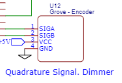
Section 9: Simulation with Rotary Encoder
This segment introduces a rotary encoder, serving as a valuable tool for simulating incremental and decremental signals corresponding to the desired setpoint for the PID controller. The encoder's rotation allows for dynamic adjustments, mimicking the real-world scenarios the system is designed to encounter during operation.
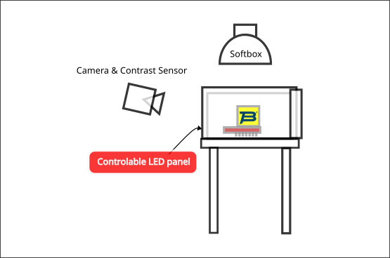
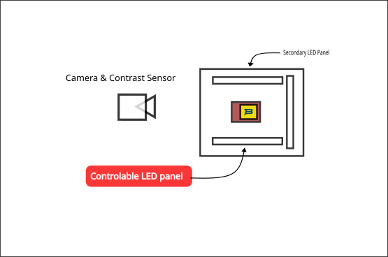
Magic Lightbox Use Cases
The Magic Lightbox serves as a versatile tool for various applications, with its primary focus being on the photography of small electronic components. Its equipped with two softbox-style LED lights on the sides of the cube. The open top allows for additional overhead lighting, and the front opening accommodates the camera.
Magic Lightbox Test Mockup Construction
The prototype of the Magic Lightbox is crafted using white foam board, with the interior forming a cube measuring 10x10x10 cm.
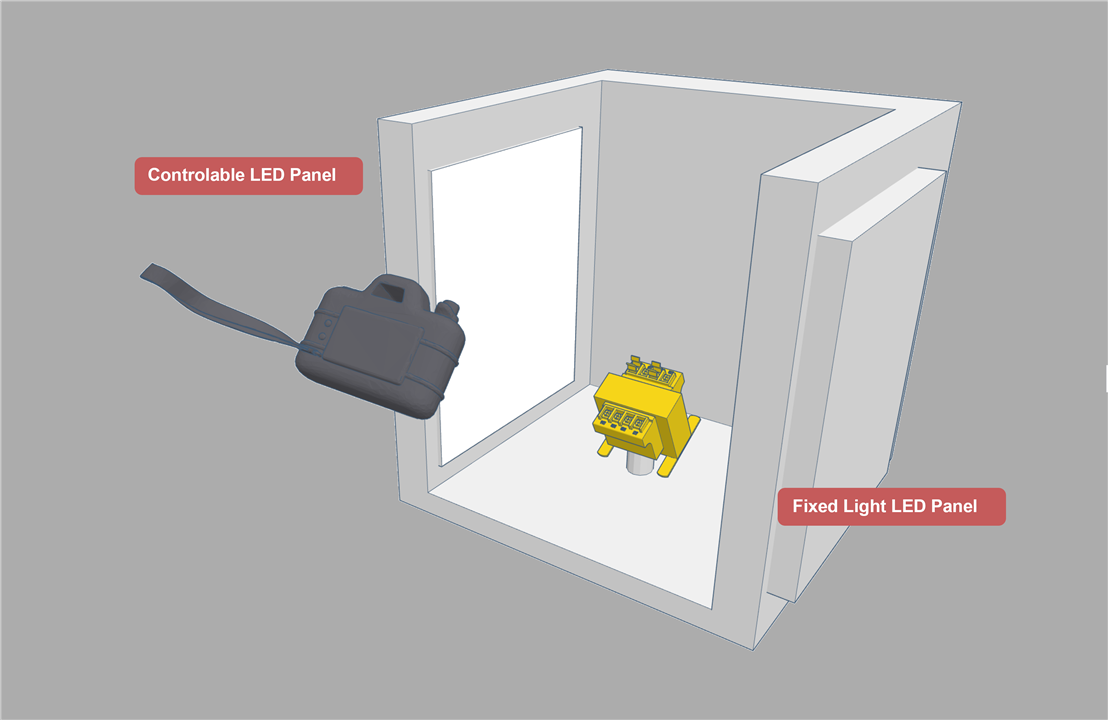
Prototype Material:
Material: White foam board
Internal Dimensions: 10x10x10 cm (Cube)
Lighting Specifications:
- LED Lights: Two LED lights are integrated, each capable of emitting up to 200 lumens.
- LED Power Rating: 2W per LED
- LED Current: Rated at 248 mA

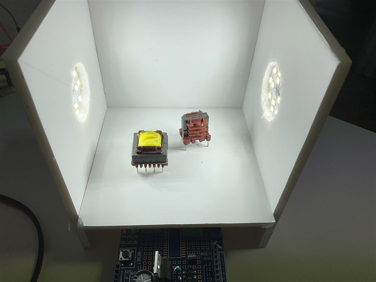
Unit Testing the Lightbox. It Turns On and Lights Up.
Before integrating the complete Magic Lightbox system, a preliminary unit test connecting the two lamps directly to a power source, bypassing our control circuit. This preliminary test allows us to ensure that each lamp unit operates as expected before incorporating them into the complete Magic Lightbox system.
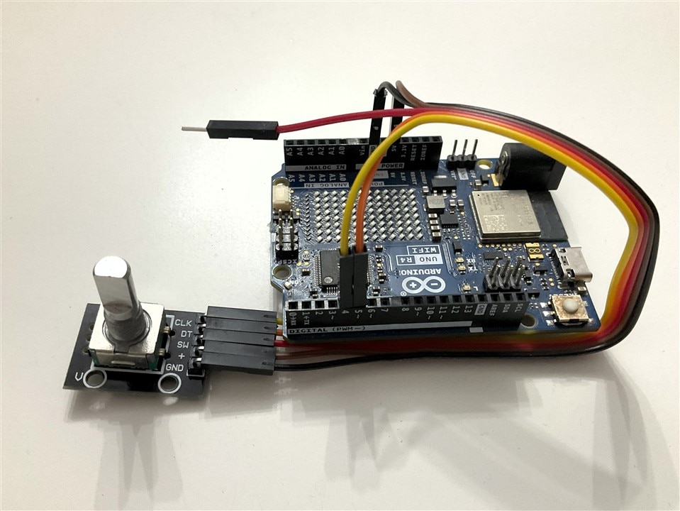
Manual dimmer. Changing the duty cycle with a rotary encoder
In the testing phase, the prototype incorporates a rotary encoder as an input device to simulate the increment and decrement signals that would be sent by the contrast sensor.
Rotary Encoder Module
// This example checks the state of the rotary encoder using interrupts and in the loop() function.
// The current position and direction is printed on output when changed.
// Credits to Matthias Hertel, http://www.mathertel.de

// Hardware setup:
// Attach a rotary encoder with output pins to
// * D4 and D5
// Swap the pins when direction is detected wrong.
// The common contact should be attached to ground.
//

#include <Arduino.h>
#include <RotaryEncoder.h>

#define PIN_IN1 D4
#define PIN_IN2 D5

// A pointer to the dynamic created rotary encoder instance.
// This will be done in setup()
RotaryEncoder *encoder = nullptr;

void checkPosition()
{
  encoder->tick(); // just call tick() to check the state.
}

void setup()
{
  Serial.begin(9600);
  while (!Serial)
    ;
  Serial.println("InterruptRotator example for the RotaryEncoder library.");

  // setup the rotary encoder functionality
  // use FOUR3 mode when PIN_IN1, PIN_IN2 signals are always HIGH in latch position.
   encoder = new RotaryEncoder(PIN_IN1, PIN_IN2, RotaryEncoder::LatchMode::FOUR3);

  // register interrupt routine
  attachInterrupt(digitalPinToInterrupt(PIN_IN1), checkPosition, CHANGE);
  attachInterrupt(digitalPinToInterrupt(PIN_IN2), checkPosition, CHANGE);
} // setup()


// Read the current position of the encoder and print out when changed.
void loop()
{
  static int pos = 0;

  encoder->tick(); // just call tick() to check the state.

  int newPos = encoder->getPosition();
  if (pos != newPos) {
    Serial.print("pos:");
    Serial.print(newPos);
    Serial.print(" dir:");
    Serial.println((int)(encoder->getDirection()));
    pos = newPos;
  } // if
} // loop ()
Prototype Firmware for the Magic Lightbox
For the prototype model of the Magic Lightbox, the firmware orchestrates the control and interaction between various components.
Here's an overview of the whole firmware functionalities:
PWM signal for MOSFET Control:
The firmware on the Arduino R4 governs the overall control system. It generates the PWM signals to regulate the MOSFET, managing the LED intensity based on the desired luminosity.
PID Controller Integration:
Incorporates a PID controller within the Arduino firmware. Ensures precise regulation of LED brightness by continuously adjusting the duty cycle based on the feedback from the contrast sensor.
Contrast Sensor Communication:
Manages communication with the contrast sensor module. Retrieves feedback on the contrast level of the scene to dynamically adjust the LED brightness.
Softstart Algorithm:
Implements a softstart algorithm to gradually increase the LED intensity, preventing sudden spikes that may impact the system.
Encoder Input Handling:
Integrates the input from the rotary encoder for simulation purposes. Mimics the signals expected from the contrast sensor, allowing comprehensive testing and validation.
ADC for Current Measurement:
Utilizes the Analog-to-Digital Converter (ADC) to measure the current in the secondary circuit, providing valuable data for system monitoring.
Simulation Mode:
Enables a simulation mode using the rotary encoder to replicate scenarios without the actual contrast sensor.
Testing Prototype Firmware for the Magic Lightbox. Simulation mode
#include "pwm.h"
#include "math.h"

#include <Arduino.h>
#include <RotaryEncoder.h>

// PWM PERIOD FOR A 100 kHz frequency, 10 us
#define PWM_PERIOD_USEC 10
// Arduino output port for the PWM signal
#define PWM_SIGNAL_PIN D3
// Encoders PINS
#define PIN_IN1 D4
#define PIN_IN2 D5

#define PWM_SOFTSTART_TARGET_DUTY_PCTE 15.0
#define PWM_TIME_BETWEEN_TRANSITIONS_MS 10

const int analogInPin = A1;  // Analog input pin that the current sensor is attached to
float sensorValue = 0.0;  // value read from the pot
float actualPercentage = 0.0;

PwmOut pwm(PWM_SIGNAL_PIN);

#define PIN_IN1 D4
#define PIN_IN2 D5

// A pointer to the dynamic created rotary encoder instance.
// This will be done in setup()
RotaryEncoder *encoder = nullptr;


/**
* PRE: Given the Duty cycle in percentage 0.0 to 100.0
* for the inverted pwm signal High off, Low on.
* POS: Sets the pwm duty cycle for the inverted
* pwm signal. High off, Low on.
*/
bool invertedPwmPerc(float invert_duty_cycle_pcte) {
  if (invert_duty_cycle_pcte > 100.0) {
    invert_duty_cycle_pcte = 100.0;
  }
  if (invert_duty_cycle_pcte < 0.0) {
    invert_duty_cycle_pcte = 0.0;
  }
  return pwm.pulse_perc(100.0 - invert_duty_cycle_pcte);
}

/**
* PRE: Given the initial duty cycle in percentage 0.0 to 100.0,
* the target duty cycle in percentage 0.0 to 100.0 for the PWM signal
* and the dalay between steps
* POS: Performs a soft transition between the two duty cycles
*/
bool pwmSoftTransition(float initial_duty_cycle, float target_duty_cycle, float time_steps_ms) {
  float pcte_increments;

  if (target_duty_cycle > initial_duty_cycle) {
    pcte_increments = .1;
  } else {
    pcte_increments = -.1;
  }

  int steps_delay = (int)(abs(target_duty_cycle- initial_duty_cycle) / .1);

  float percentage = initial_duty_cycle;
  for (int i = 0; i < steps_delay; ++i) {
    percentage += pcte_increments;
    bool success = invertedPwmPerc(percentage);
    if (!success) {
      return false;
    }
    actualPercentage = percentage;
    delay(time_steps_ms);
  }
  return true;

}

/**
* PRE: Given the target duty cycle in percentage 0.0 to 100.0 for the PWM signal
* and the delay between steps in ms
* POST: Performs a soft start till reaching the target duty cycle
*/
bool pwmSoftStart(float target_duty_cycle, float time_steps_ms) {
    return pwmSoftTransition(0.0, target_duty_cycle, time_steps_ms);
}

void setUpPWMSignal() {
  pwm.begin(PWM_PERIOD_USEC, 0.0);
  pwmSoftStart(PWM_SOFTSTART_TARGET_DUTY_PCTE, PWM_TIME_BETWEEN_TRANSITIONS_MS);
}

void setUpADCForCurrentSensor() {
  analogReadResolution(14); //change to 14-bit resolution
}


void checkPosition()
{
  encoder->tick(); // just call tick() to check the state.
}

void setup()
{
  Serial.begin(9600);
  while (!Serial)
    ;
  Serial.println("InterruptRotator example for the RotaryEncoder library.");

  // setup the rotary encoder functionality
  // use FOUR3 mode when PIN_IN1, PIN_IN2 signals are always HIGH in latch position.
   encoder = new RotaryEncoder(PIN_IN1, PIN_IN2, RotaryEncoder::LatchMode::FOUR3);

  // register interrupt routine
  attachInterrupt(digitalPinToInterrupt(PIN_IN1), checkPosition, CHANGE);
  attachInterrupt(digitalPinToInterrupt(PIN_IN2), checkPosition, CHANGE);

  setUpADCForCurrentSensor();

  setUpPWMSignal();
} // setup()


// Read the current position of the encoder and print out when changed.
void loop()
{
  static int pos = 0;

  encoder->tick(); // just call tick() to check the state.

   int newPos = encoder->getPosition();


    if (pos != newPos) {

    if ((int)(encoder->getDirection()) == 1) {
      if (actualPercentage < 45) {
        pwmSoftTransition(actualPercentage, actualPercentage + 1, PWM_TIME_BETWEEN_TRANSITIONS_MS);
      }

    } else if (actualPercentage > 0 ){
        pwmSoftTransition(actualPercentage, actualPercentage - 1, PWM_TIME_BETWEEN_TRANSITIONS_MS);
    };
    pos = newPos;
  }

      // read the analog in value:
  float sensorValueOld = sensorValue;
  sensorValue = 0.0;

  sensorValue += analogRead(analogInPin);
    // wait 2 milliseconds before the next loop for the analog-to-digital
    // converter to settle after the last reading:
     delay(2);


} // loop ()
Magic Lightbox Blog Series
- Blog 1 - Magic Lightbox: Smart LED Dimmer Flyback Driver Project Introduction.
- Blog 2 - Magic Lightbox: Understanding Flyback Transformers. How to characterize them.
- Blog 3 - Magic Lightbox: Understanding Flyback Converters.
- Blog 4 - Magic Light Box: DC/DC Flyback Converter Testbench and LED Dimmer Driver
- Blog 5 - Magic Light Box: Building The Prototype
- Final - Magic Lightbox: Project Summary
Top Comments