


Table of Contents
- To start, a little history of Bourns and Kaschke Components
- A quick look at the components manufactured by Kaschke
- Flybacks transformers
- Galvanic Isolation and Safety Standards
- Push-Pull Transformers vs Flyback Transformer
- Continuous mode (CCM) and Discontinuous Mode (DCM)
- Identifying transformer wirings and polarities
- Calculating transformer wirings turn ratios
- Measuring the transformer impedances
- Impedance measurements
- Individual, parallel or series operating mode of the outputs.
- Transformers types comparison
- Appendix
- Examining Model 063932 SP-E 16/5 Flyback Transformer
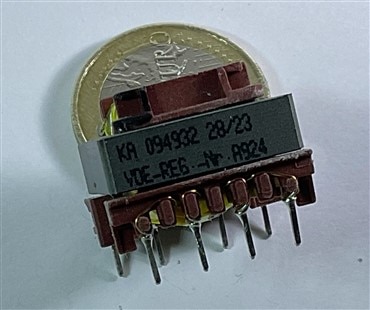
- Examining Model 094932 SP-E 20/6 Flyback Transformer
- Examining BA60951CS – Flyback Transformer
- Bourns PFBR45 Power Line Communication Transformers
- Examining PFBR45-ST13150S PLC Transformer
- Examining PFBR45-SP13150S PLC Transformer
- Examining HCT Series - High Clearance and Creepage Distance Transformers
- Summary and conclusions
- Magic Lightbox Blog Series
To start, a little history of Bourns and Kaschke Components
Just like many others, as I went through the datasheets of the Flyback Transformers provided in the competition kit, I encountered acronyms and names that confused me. So, I started digging for answers. One acronym that stumped not just me but other competitors too was 'SP' on several Flyback transformers. After checking the certifications, I figured out that 'SP' stands for SmartPower. Turns out, SmartPower is what Kaschke Components calls a series of transformers designed specifically for controlling Switched-Mode Power Supplies (SMPS) using integrated circuits (ICs).
In 2021, Bourns, the sponsor of this Experimenting with Flyback Transformers competition, acquired Kaschke Components, a market leader in the field of customized magnetic components and ferrite cores. Kaschke Components is one of the leading manufacturers of inductive components and ferrites in Europe.
![]()

Later this year, 2023, Bourns incorporated into its Bourns Custom Magnetics Product Line the following series of Kaschke SMPS transformers and EMC Filter Chokes
- Model 063xxx and 093830 Series SP-E16/5 Flyback Transformers
- Model 0949xx Series SP-E 20/6 Flyback Transformers
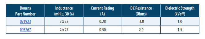
- Model 071923/093267 EMC Filter Chokes
Bourns/Kaschke Plug & Play transformers are designed for standard transformer solutions for Switched-Mode Power Supplies (SMPS) control IC’s. The designs meet the necessary safety and performance criteria for many applications.
The magnetic components kit supplied for this challenge contains 9 components from these three series. In this blog we will analyze them, understanding their characteristics and comparing them with other types of Bourns transformers, the PFBR45 series Power Line Communication Transformers, the BA60951CS Flyback Transformer and the HTC series of pulse transformers.
A quick look at the components manufactured by Kaschke
The kit contains components from three of the Kaschke series incorporated into the Bourns catalogue:
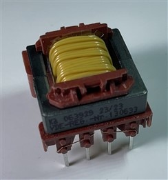
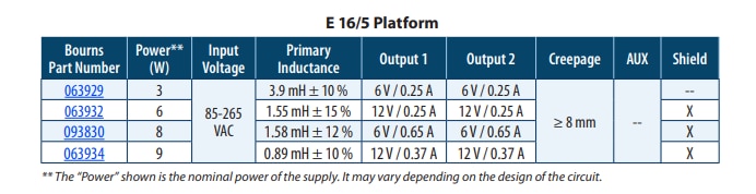
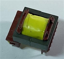
Model 063xxx and 093830 Series SP-E16/5 Flyback Transformers are based on a standard E 16/4,7 power ferrite core with a high clearance, high creepage distance coil construction designed for various silicon controller families. The Model 063xxx Transformer Series is capable of transferring up to 9 watts and is optimized for a working frequency of 132 kHz.
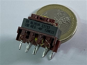
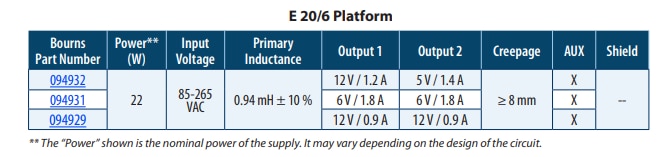
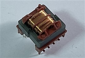
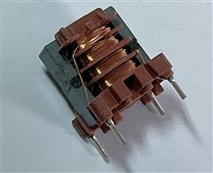
Model 0949xx Series SP-E 20/6 Flyback Transformers are based on a standard E20/6 power ferrite core shape with a high clearance and high creepage distance coil construction designed for various silicon controller families. These transformers are capable of transferring up to 22 watts and are optimized for a working frequency of 132 kHz.
Model 071923/093267 EMC Filter Chokes are characterized by wide-band performance of interference suppression with excellent attenuation of symmetric and asymmetric noise. These EMC filter chokes, ideally designed for the SmartPower Safety Transformer series, also target applications such as low power Switched-Mode Power Supplies (SMPS), drives and control circuits, home appliances and industrial applications.
Flybacks transformers
One of the key takeaways from this experimentation challenge is gaining a clear understanding of what a Flyback transformer is. Despite having encountered them throughout my career as a dedicated IT technician and studying them in university, I never gave them the special attention they deserved until now.
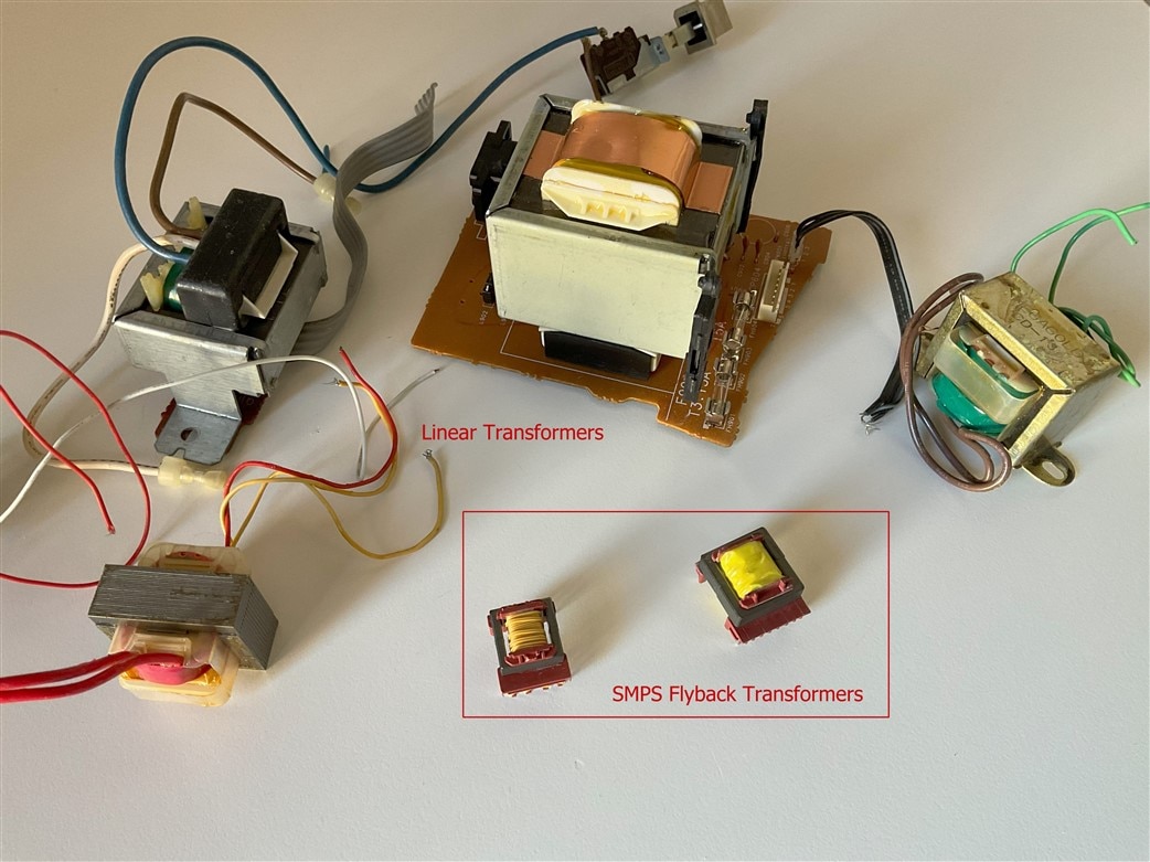
Size comparison between Linear and Switched Mode Power Transformers
The two most prevalent types of power supplies are coil, also known as linear, and switched-mode power supplies (SMPS). In an SMPS, the AC line power is directly converted into DC voltage, which is then transformed into a higher frequency AC signal. This high-frequency signal is utilized in the regulator circuit to generate the desired current and voltage. Consequently, SMPS employs a smaller and lighter transformer that adjusts the voltage as needed, leading to a higher power conversion ratio. In contrast, a coil or linear power supply applies the AC line voltage to a power transformer to either decrease or increase the voltage before reaching the regulator circuit. This results in the need for a larger and heavier power supply.
A flyback transformer is made up of a primary and secondary inductive winding on a core material. In some cases, a flyback transformer is also referred to as a coupled inductor. Like regular transformers, the flyback transformer converts primary voltage to secondary voltage through the ratio of the winding and the core material.
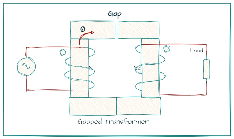
The air gap, is a non-magnetic part of a magnetic circuit. It is usually connected magnetically in series with the rest of the circuit, so that a substantial part of the magnetic flux (or magnetic field) flows through the gap. In classical transformers air gap is usually avoided. The role of transformer is to deliver the energy from the primary winding to the secondary winding instantaneously, without the need for energy storage.
Any air gap in the magnetic core increases leakage inductance and stores additional energy, which needs to be cyclically transferred or dissipated. All these factors impact efficiency of energy transformation.
The air gap lowers the total inductance of the primary winding and causes an increase in apparent power through the increase of magnetizing current. Unlike a regular transformer, which continuously transfers the energy from the primary to secondary windings, the flyback transformer store the energy in its core prior to releasing it.
In a typical flyback transformer, you’ll find a switch connected to the primary winding. The switch is usually in the form of a power transistor. When the switch is turned on, the magnetic field is gradually built-up on the core. A diode is placed on the secondary part of the transformer so that no current goes through during the energy build up stage.
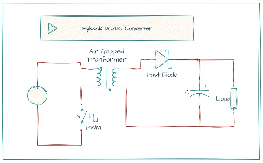
When the transistor is turned off, the current is cut off from the primary winding. As such, the voltage polarity changes to the opposite on the secondary winding and current is released on the circuit.
Placing a bypass capacitor after the secondary winding helps to smoothen the ripples generated by the fast switching speed of the transistor.
Galvanic Isolation and Safety Standards
In my role as an auditor and specialist in the implementation of information security management systems, I'm well-versed in handling international security standards. Information security is a vast arena, covering everything from the physical infrastructures where data resides, including buildings and computers, to considering individuals as vessels of information. I've always had a bit of a qualm about this perspective, but it gains significance when urging the company to regard people as valuable information assets. This is why I am very interested in what circuits that use flyback transformers contribute to safety.
Flyback transformers provide galvanic isolation. Galvanic isolation is a technique that provides electrical separation between circuits or systems to enhance safety, prevent ground loops, and protect electronic components from electrical hazards.
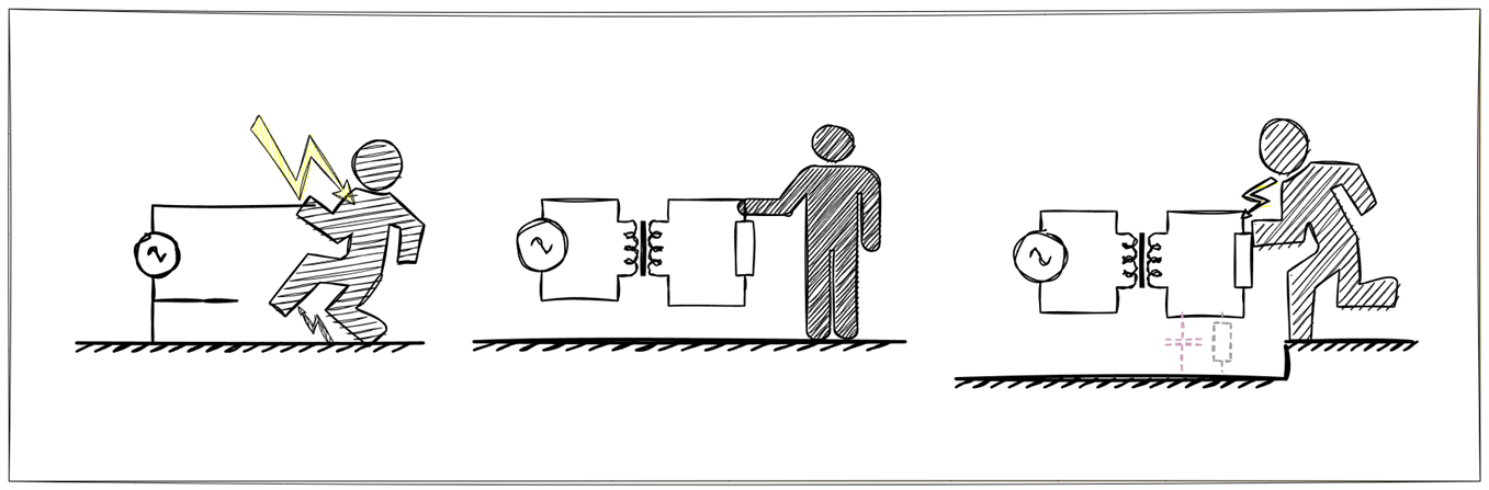
Electrical risks without and with galvanic isolation.
International safety standards are constantly changing and it is difficult to stay up to date with them if you are not a specialist in safety standards. I have tried to make a small summary of the standards under which this Bourns components are been designed. Safety is super important, and we're talking about things like fire risks and electric shocks here. It's a good idea to really dig into all the certifications these components have earned to make sure they're up to snuff in protecting against these kinds of hazards.
Bourns SmartPower Series SP-E16/5 Flyback Transformers and Series SP-E 20/6 Flyback Transformers comply with EN 62368, EN 60335 and EN 61558 safety standards. All transformers are also VDE approved.
- IEC 62368: is a product safety standard that classifies energy sources, prescribes safeguards against those energy sources, and provides guidance on the application of, and requirements for, those safeguards. The prescribed safeguards are intended to reduce the likelihood of pain, injury and, in the case of fire, property damage.
- IEC 60335: deals with the safety of electrical appliances for household and similar purposes, their rated voltage being not more than 250 V for single-phase appliances and 480 V for other appliances including direct current (DC) supplied appliances and battery-operated appliances. Appliances not intended for normal household use but which nevertheless may be a source of danger to the public, such as appliances intended to be used by laymen in shops, in light industry and on farms, are within the scope of this standard.
- IEC 61558: deals with the safety of separating transformers for general applications and power supply units incorporating separating transformers for general applications. Transformers incorporating electronic circuits are also covered by this standard.
- The VDE e. V. (German: Verband der Elektrotechnik, Elektronik und Informationstechnik) is a German technical-scientific association. VDE is best known for creating and maintaining standards in the field of electric safety and has a strong influence on the DIN (German Institute for Standardization).
Push-Pull Transformers vs Flyback Transformer
In the last Element14 experimenting challenge, while tinkering with magnetic components, I got my hands on a duo of pulse transformers that are typically employed in DC/DC converter designs featuring push-pull topology. Let's take a pause to draw a comparison between these two topologies. Since I've got units of both - the flyback transformers and pulse transformers - I intend to delve into the details and conduct some measurements, and see how they stack up against each other.
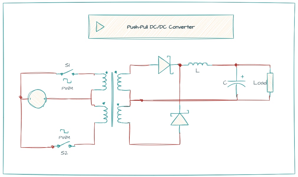
Push-pull transformers, such as the Bourns HCTSM8 series, are widely employed in push-pull DC/DC converter setups. While flyback converters effectively handle a broad range of input voltages, they often present electromagnetic interference (EMI) issues and generally necessitate intricate closed-loop control systems for stable operation. In contrast, a push-pull transformer operates more straightforwardly in an open-loop configuration. Schematic source: SN6501-Q1 Transformer Driver for Isolated Power Supplies
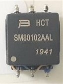
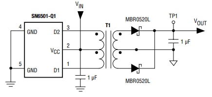
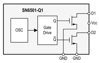
HCTSM8 Series Transformer & Typical Application
Comparatively, flyback converter topologies exhibit lower efficiency and higher energy waste than push-pull topologies, which ensure efficiency with stable input and output current. Unlike typical flyback topologies, the push-pull configuration stands out for its high efficiency and stability in handling input and output current.
Especially for low voltage applications, a push-pull transformer offers the added benefit of space efficiency. It typically comes in a smaller size than flyback transformers, making it a compact and efficient choice for specific electronic setups.
And because push-pull transformers are designed as “pure” transformers, they usually have physically smaller ferrite cores compared to flyback transformers. Plus, there is no gap required in the ferrite core of a push-pull transformer, and, therefore, the effective permeability remains high and the magnetizing inductance can be quite high for a low number of turns.
Given a sufficiently high switching frequency and low DC voltages, the flux generated (Volt Seconds per Turn) remains well below the saturation point. Contrast this result with the gapped ferrite core in a flyback transformer where more turns are needed to ensure the current does not saturate the transformer. If there are tight space considerations and restrictions, the DC resistance will inevitably increase with the higher number of turns, resulting in reduced efficiency.
In the next graph a comparison of the frequency response of two coils, one form a flyback transformer and the other one from a push-pull transformer:
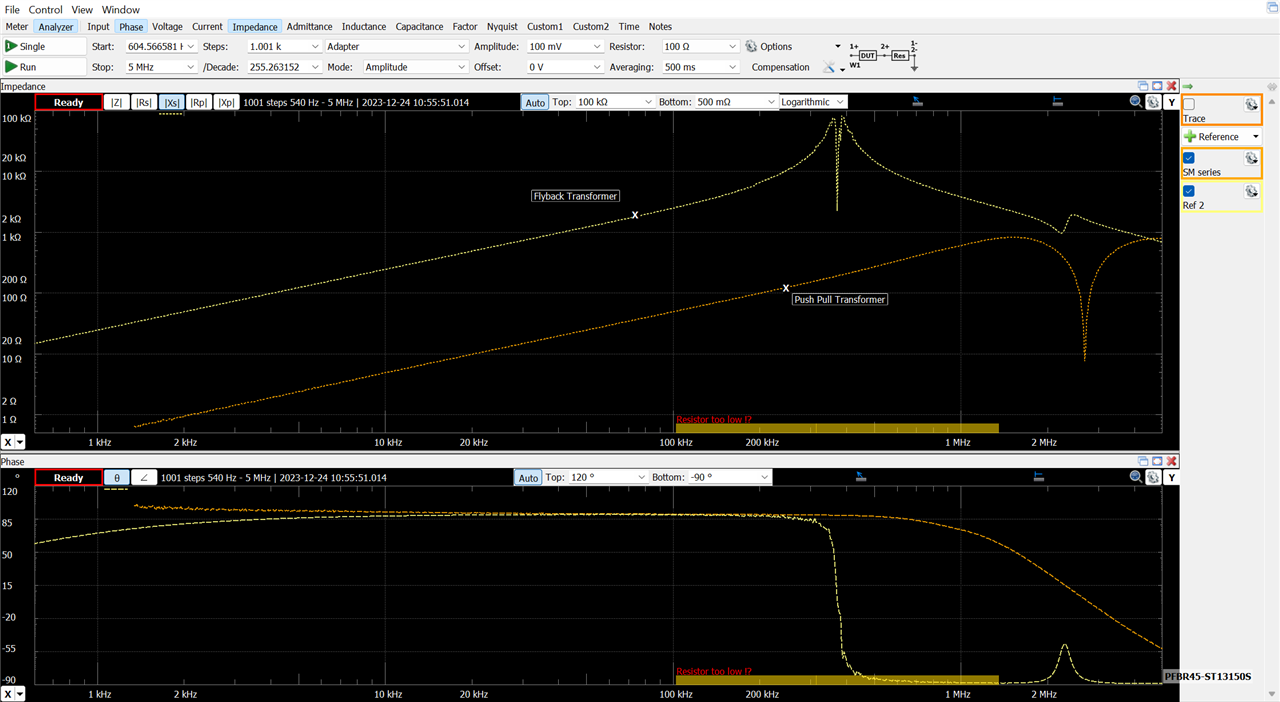
Inductance response: Flyback transformer primary winding vs push-pull transformer primary winding
Push-pull transformers, designed as "pure" transformers, usually incorporate physically smaller ferrite cores compared to flyback transformers. Additionally, there's no need for a gap in the ferrite core of a push-pull transformer, ensuring high effective permeability and potentially high magnetizing inductance with fewer turns. More practical results at the end of the blog.
Continuous mode (CCM) and Discontinuous Mode (DCM)
When designing a flyback transformer, the designer faces a lot of design restrictions, one of which should not be overlooked is the mode of operation in which the transformer will work.
The flyback transformer can be used in a continuous or non-continuous mode. In the discontinuous mode (DCM), the energy is fully transferred to the secondary winding before the transistor is turned back on whereas, in continuous mode (CCM), the transistor is turned on before the energy is fully depleted.
Although the two operational modes of a flyback converter might look similar, but each mode has its own set of pros and cons. One must carefully consider these factors during the design process, as the chosen mode significantly impacts efficiency, transformer performance, regulation, electromagnetic interference (EMI), and overall cost.
Concerning efficiency, Discontinuous Conduction Mode (DCM) generally outperforms Continuous Conduction Mode (CCM) due to reduced diode reverse recovery loss and a smoother MOSFET turn-on. However, an excessively small duty cycle in DCM can result in a high current charging the primary inductor, lowering the converter's overall efficiency. One have to choose a reasonable duty cycle to optimize the advantages offered by DCM.
In terms of transformer size, Discontinuous Conduction Mode (DCM) theoretically allows for a smaller transformer due to a reduced inductance requirement. However, larger wire gauges are needed because of increased current spikes. As a result, the transformer sizes in both DCM and Continuous Conduction Mode (CCM) are generally similar. DCM's higher efficiency allows for an increased switching frequency, enabling the use of a smaller transformer.
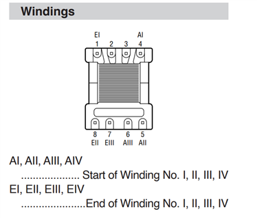
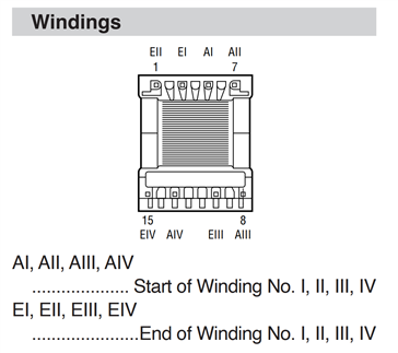
Identifying transformer wirings and polarities
To figure out the different components of a transformer we can use a Digital Multimeter (DMM), start by turning on the DMM and checking out the pairs of wires on the transformer. Measure the resistance of each pair by touching the DMM probes to the wires, noting the readings.

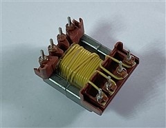
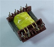
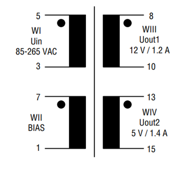
Bourns 094932 SMPS Flyback Transformer
For determining the polarity of the windings, we can perform a polarizing test by applying a small AC voltage (using a low-voltage AC power source) to one winding and observing the direction of current flow in the other windings. We can obtain the direction of current through several voltmeter measurements as in the diagram shown below:
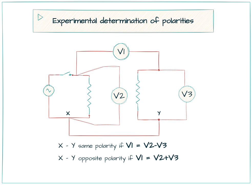
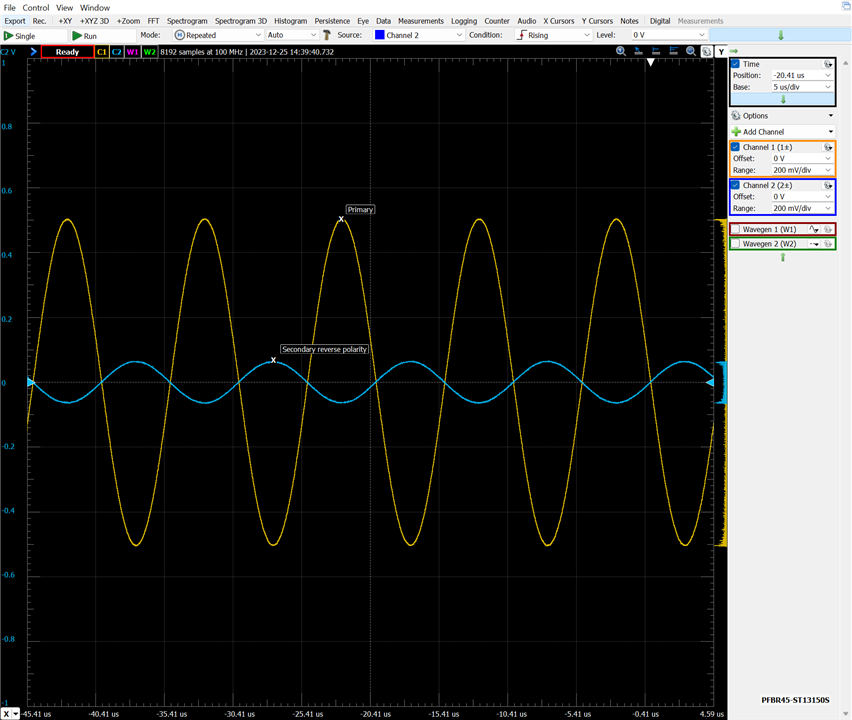
If we have a two-channel oscilloscope and a signal generator it would be much easier. Fortunately, Digilent's Analog Discovery 2 provides us with an all-in-one. Same polarity vs opposite polarity with an oscilloscope. Sine wave 100 kHz applied to the primary:

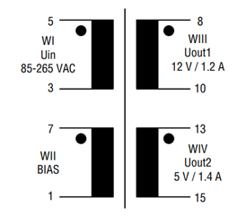
Identifying wiring polarities for the Bourns 094932 SMPS Flyback Transformer
Calculating transformer wirings turn ratios
The turns ratio (N1/N2) of a transformer can be calculated using the relationship between the primary and secondary winding inductances and their respective turns.The turns ratio is the square root of the ratio of inductances. This formula assumes an ideal transformer, neglecting factors like core losses and leakage inductance.
N1/N2 = sqrt(L1/L2)
Here:
- N1 is the number of turns in the primary winding,
- N2 is the number of turns in the secondary winding,
- L1 is the inductance of the primary winding,
- L2 is the inductance of the secondary winding.
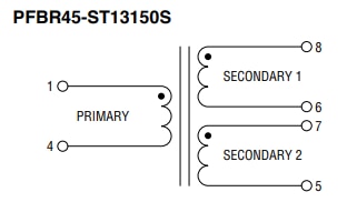
Let's check it empirically with the PFBR45-ST13150S PLC transformer

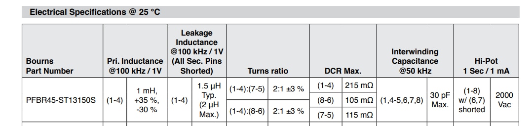
Inductance measured applying a 100 kHz sine wave.
| Primary 1-4 | Secondary 1 8-6 | Secondary 2 7-5 | |
| Ls Series Inductance | 1.08967844 mH | 280.822975 uH | 281.295945 uH |
|
sqrt(L1/L2) sqrt(1.08967844 / 0.280822975) = 1.96984865901 |
sqrt(L1/L3) sqrt(1.08967844 / 0.281295945) = 1.96819191404 |
||
| Turns ratio Primary/other |
aprox. 2:1 |
aprox. 2:1 |
The result is very close to that indicated in the data sheets.
Measuring the transformer impedances
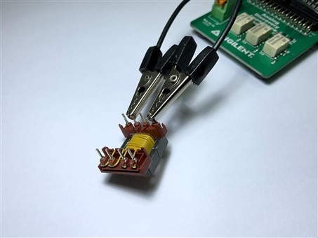
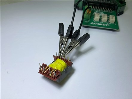
For the previous impedance measurements, to empirically obtain the turns ratio between two windings we have used an Impedance Analyzer.
An impedance analyzer is a type of electronic test equipment used to measure complex electrical impedance as a function of test frequency. An impedance analyzer takes sensitive measurements of both current and voltage are applied to the device under test (DUT) while the measurement frequency is varied.
In the image the Analog Discovery Impedance Analyzer Adapter. With this device I have analyzed the inductive, resistive and capacitive behavior of the different windings of the transformers in different configurations.
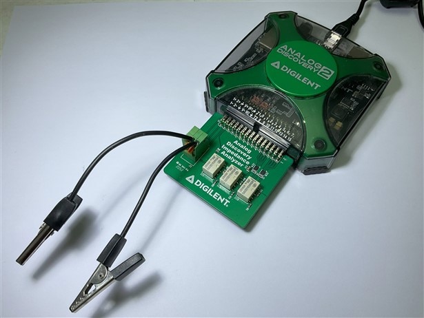
It uses the one wave generator, and the two oscilloscope channels from the Analog Discovery 2 device, and a reference resistor.
The impedance analyzer circuit is constructed as in the circuit below.
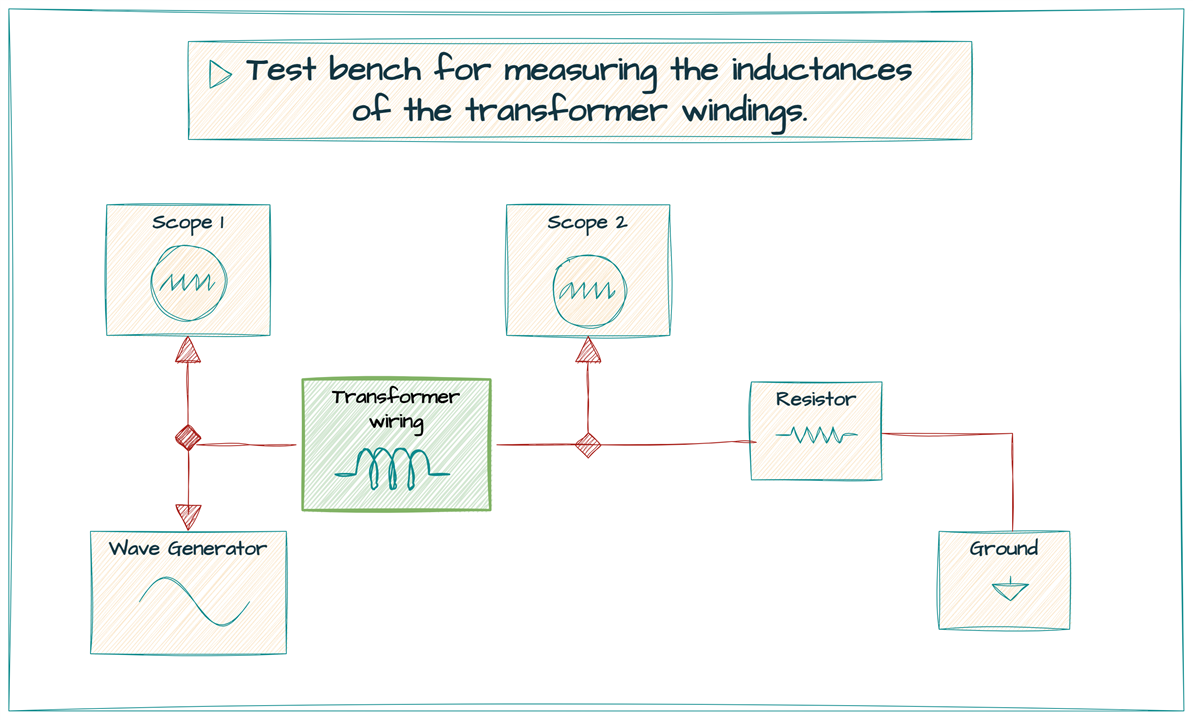
The Load, here the a winding of the transformer, to be analyzed and Resistor is the reference resistor that is already loaded on the board. The resistor value depends on the load value and frequency. The Analog Discovery 2 can automatically select the most appropriate component for the job that it needs to do.
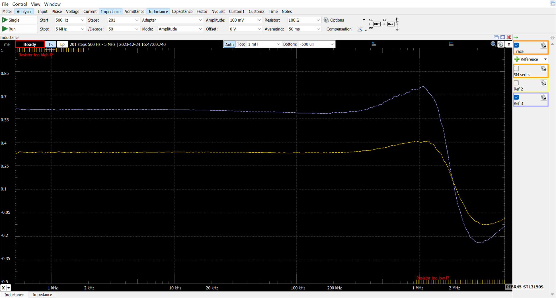
Impedance measurements
Here a compilation of the formulas we will use for the different characterization parameters in series mode:
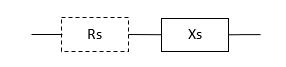
- |Z| Impedance = sqrt (Rs^2 + Xs^2)
- Θ Phase = tan-1 (Xs / Rs) with Rs Series Resistance
- Gs Series Conductance = 1 / Rs
- Xs Series Reactance = ω × Ls = -1 / (ω × Cs)
- Bs Series Susceptance = 1 / Xs
- Ls Series Inductance = Xs / ω
- Cs Series Capacitance = -1 / (ω × Xs)
- D Dissipation Factor = Rs / Xs = Rs / (ω × Ls) = 1 / (ω × Ls × Gs) = ω × Cs × Rs = ω × Cs / Gs
- Q Quality Factor = Xs / Rs = ω × Ls / Rs = ω × Ls × Gs = 1 / (ω × Cs × Rs) = Gs / (ω × Cs)
- ω Angular Frequency = 2 × π × Frequency
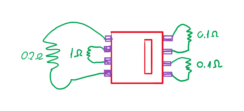
Individual, parallel or series operating mode of the outputs.
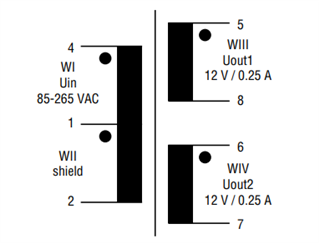
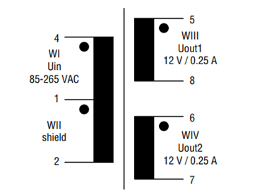
Model 063xxx and 093830 Series SP-E16/5 Flyback Transformers and Model 0949xx Series SP-E 20/6 Flyback Transformers offer two outputs with reinforced insulation.
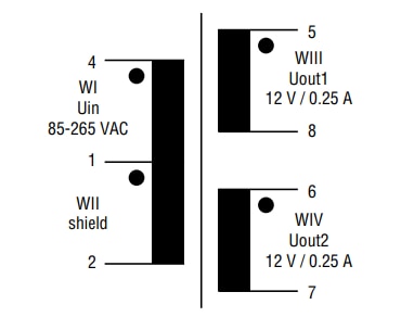
These two outputs can be operated either individually, in parallel or in serie:
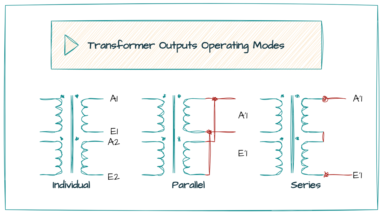
When we choose a determinate operating mode we must consider several aspects:
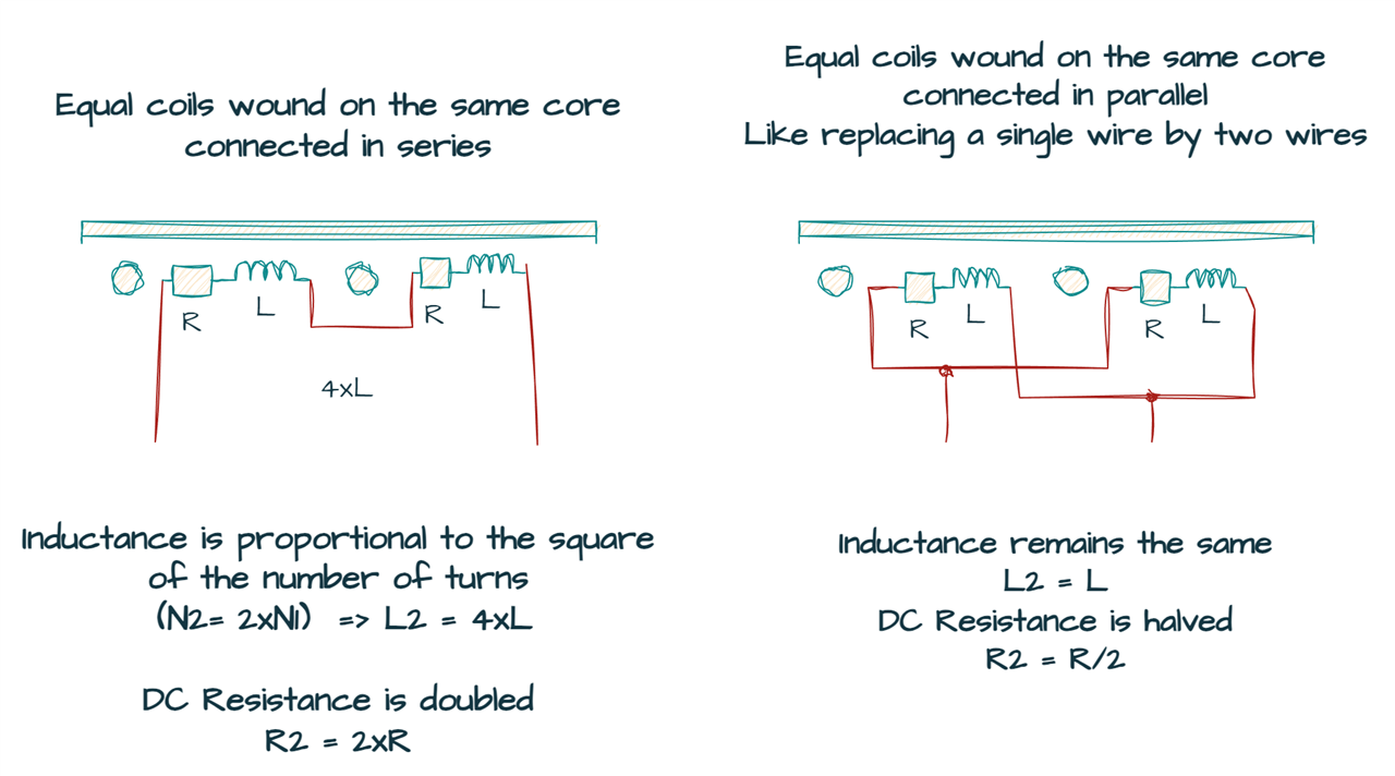
Inductance (L): Inductance refers to the property that influences the transformer's ability to store energy in its magnetic field. The energy stored in the magnetic field is directly proportional to the square of the current and the inductance. The inductance of a transformer depends on the number of turns in the coils and the core's cross-sectional area. More turns and a larger core area result in higher inductance. If two coils with equal turns are wound on the same core and connected in series, their inductance is four times that of the parallel configuration.
When connecting two equal-turn windings in parallel on the same core, the inductance remains the same, but the DC resistance is halved. This is different from connecting separate inductors in parallel, where the inductance is halved. When in parallel, the inductance stays the same because it's like replacing a single wire with two wires.
If the transformer winding has multiple wires intended for parallel connection, we can consider connecting them in series to increase inductance or turns ratio. However, we must carefully analyze all variables before attempting alternative configurations.
Inductance comparison for the different three modes, individual, parallel and series configuration mode for the Bourns 063932 SP-E 16/5 Flyback Transformer.
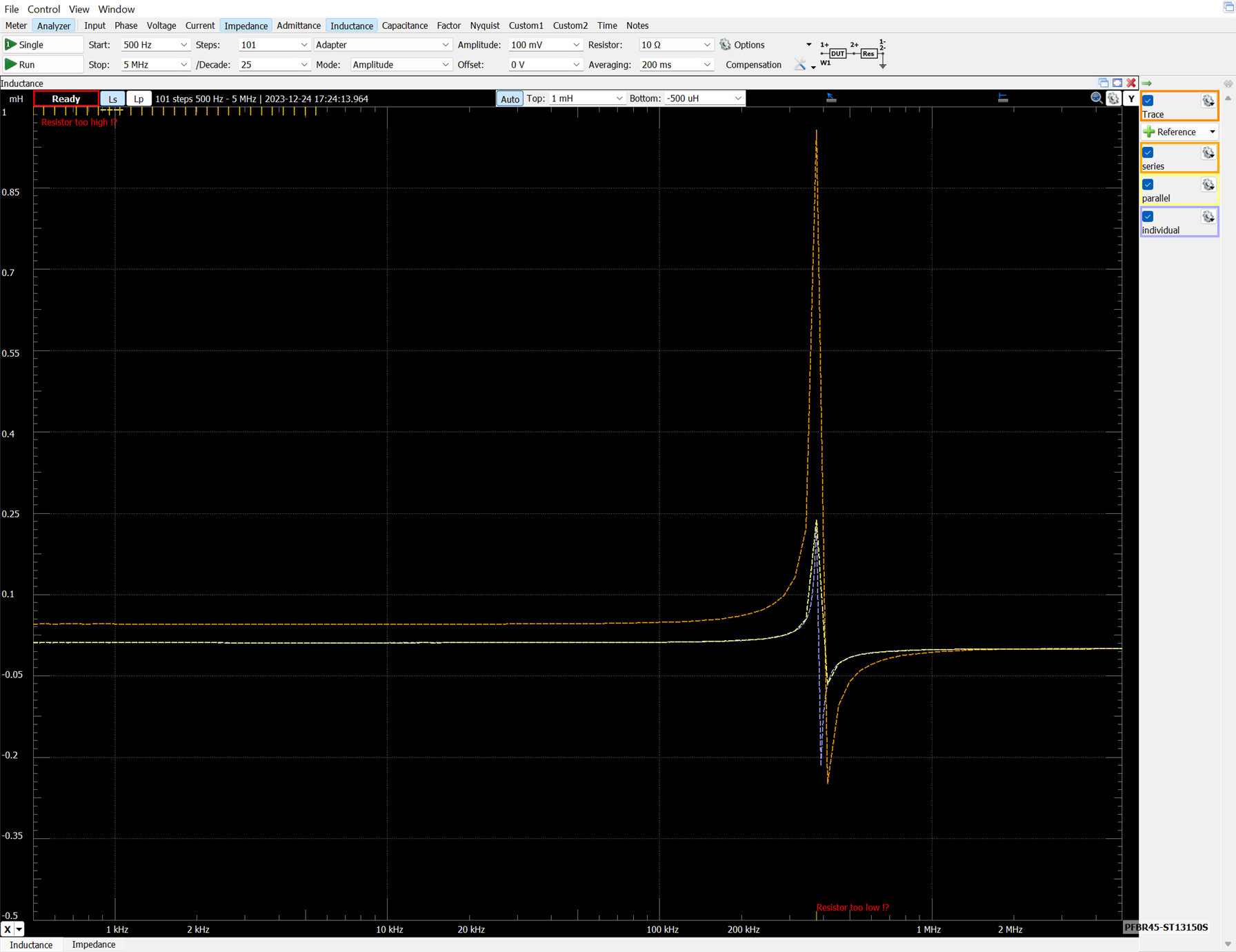
DC Resistance (DCR): DC Resistance assumes significance in Flyback Transformers as it characterizes the opposition to direct current flow within the winding coils. When connecting two equal windings in parallel, the combined DC resistance is halved, impacting the transformer's efficiency and power dissipation characteristics. Conversely, when connecting two equal windings in series, the combined DC resistance is two times that of each winding. When equal windings are connected in series, the DC resistance is fourfold (4×) compared to the same windings in a parallel combination.
RMS Current: Root Mean Square (RMS) current, a critical parameter in Flyback Transformers, is intricately linked to the transformer's thermal behavior. It is contingent upon the temperature rise, and the relationship between series and parallel connections directly influences the RMS current.
The current flowing through the series connection causing the same temperature rise as the parallel connection is calculated as:
Iseries^2 x DCRseries = Iparallel^2 x DCRparallel, then Is/Is = sqrt(DCRparallel/DCRseries ) = 1/2
For equal windings, Irms for the series connection is half that of the parallel connection.
Saturation Current: Saturation current is closely tied to the maximum magnetic flux the transformer can withstand before reaching saturation. This phenomenon is crucial for preventing core saturation, which could lead to a reduction in inductance and overall performance.
Saturation of ferrite or powdered iron cores is related to the energy storage capability of the inductor. With two equal windings in parallel, the saturation current is the same. In series, the volt-time product doubles, quadrupling inductance and halving the saturation current compared to a single winding.
Self Resonant Frequency (SRF): The self resonant frequency of two bifilar-wound wires depends on the inductance and capacitance influencing the transformer's natural frequency of oscillation. When connected in series, the interwinding capacitance and winding capacitance to ground may change. The effective capacitance change may be small compared to inductance but should be considered. The series SRF will be about 1/ 2 , approximately half that of the parallel configuration.
Voltage / Isolation / Safety: Isolation between windings is designed for separate use, as with coupled inductors or transformers. Bifilar-wound wires may have limited isolation, so thorough testing is recommended to ensure safe isolation voltage for the application.
Outputs for the Bourns 063932 SP-E 16/5 Flyback Transformer. Examining the response of impedances to frequency.
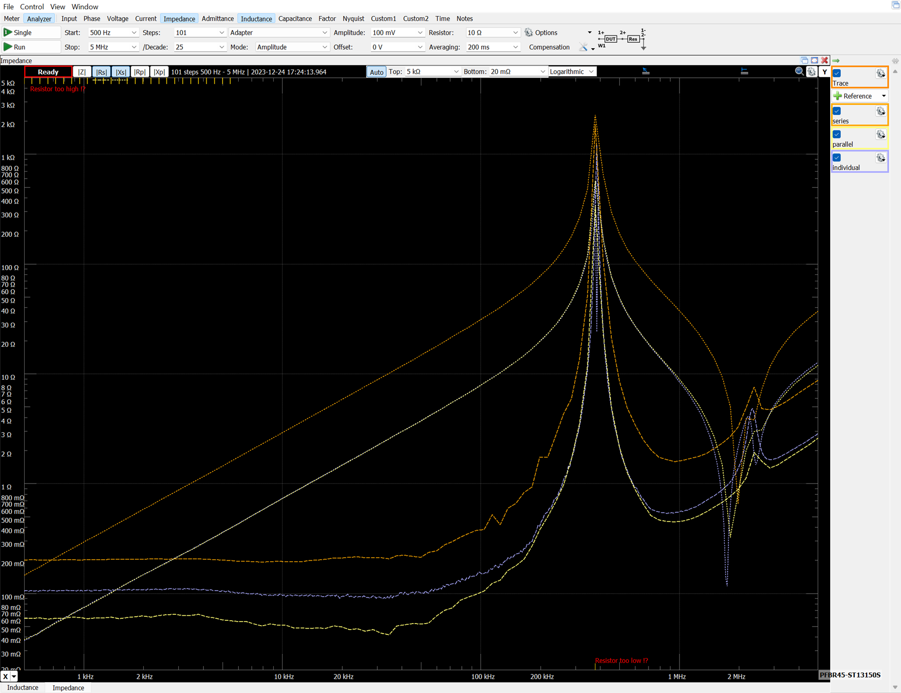
In series, the SRF is approximately half that of the parallel configuration due to the increased inductance.
Amplitude 0.1V, Resistor 10Ω Frequency 100 kHz
| WIII 5-8 | WIV 6-7 | Series | Parallel | |
| Ls Series Inductance | 12.4349263 uH | 12.4234684 uH | 48.9916305 uH | 12.3645565 uH |
| |Z| Impedance | 7.81443603 Ω | 7.80734698 Ω | 30.7846309 Ω | 7.769542 Ω |
| Rs Series Resistance | 144.785743 mΩ | 150.546082 mΩ | 374.79241 mΩ | 101.422428 mΩ |
| Xs Series Reactance | 7.81309462 Ω | 7.80589539 Ω | 30.7823493 Ω | 7.76888 Ω |
| ∠ Input Phase | 37.6081431 ° | 37.5668892 ° | 71.3883966 ° | 37.5695579 ° |
| θ Phase | 88.938364 ° | 88.8951189 ° | 89.3024261 ° | 89.2520483 ° |
| D Dissipation | 0.018531165 | 0.019286203 | 0.012175562 | 0.013054961 |
| Q Quality | 53.9631488 | 51.8505381 | 82.1317307 | 76.5992308 |
Let's check if If the inductance of the series configuration is four times that of the parallel configuration when two coils with equal turns are wound on the same core.
| WIII 5-8 | WIV 6-7 | Series | Parallel | |
| Ls Series Inductance | 12.4349263 uH | 12.4234684 uH | 48.9916305 uH | 12.3645565 uH |
| Inductance Relation: series vs parallel configuration inductances |
48.9916305 uH / 12.3645565 uH = 3.94 ≈ x4 (series inductance is four times that of the parallel configuration) |
|||
Transformers types comparison
We have seen a lot of theory about different transformers, in this section we are going to take values on real transformers of the three types that we have mentioned, flyback transformers, push-pull transformers and PLC transformers.
| Flyback Transformer | Flyback Transformer | Flyback Transformer | PLC Transformer | PLC Transformer | Push-Pull Transformer | |
|---|---|---|---|---|---|---|
|
 |
 |
 |
 |
 |
|
|
063932 SP-E 16/5 |
094932 SP-E 20/6 |
BA60951CS |
PFBR45-ST13150S |
PFBR45-SP13150S |
HCTSM80102AAL |
|
| Nominal Inductance | 1.55 mH | 0.94 mH | 0.025 mH | 1 mH | 1.15 mH | 0.250 mH |
| Leakage Inductance max | 60 µH | 35 µH | 0.6 µH | 0.25 µH | 1.3 µH | 0.6 µH |
| Maximum Transmissible Power | 6W | 22W | 2.25W | 0.45W | 0.45W | 1.75W |
| Volume mm^3 |
14.5x19x22 6061 mm3 |
20x15x17.5 5250 mm3 |
5.97x13.6x15 1217 mm3 |
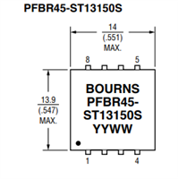
15.4x14x13.9 2996 mm3 |
12.7x13.5x15.4 2640 mm3 |
10x12.3x10.8 1328 mm3 |
|
|
|
|
|
|
|

Flyback transformers may have higher DC resistance in the windings due to their design emphasizing energy storage and release. Push-pull transformers typically have lower leakage inductance
Appendix
Some appendices are added below as annexed documentation, with the data obtained in the different tests with the transformer windings.
You can skip it or I invite you to click and zoom in on the photos and graphics.
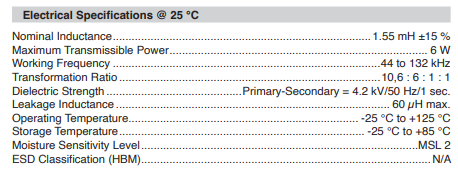
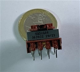
Examining Model 063932 SP-E 16/5 Flyback Transformer
063932 SP-E 16/5 Flyback Transformer: Buy Now
Bourns SMPS Flyback Transformer, 250 mA, 44khz to 132khz, 6 W, 85v at 265v
Amplitude 0.1V, Resistor 10Ω Frequency 100 kHz
| WI 1 4-1 | WI-WII 4-2 | WII 1-2 | WIII 5-8 | WIV 6-7 | |
| Ls Series Inductance | 1.45310055 mH | 3.78585954 mH | 523.994067 uH | 14.9685025 uH | 14.8770987 uH |
| |Z| Impedance | 914.405684 Ω | 2.37891466 kΩ | 329.251215 Ω | 9.40634805 Ω | 9.34820614 Ω |
| Rs Series Resistance | 50.5023702 Ω | 29.9829335 Ω | 3.24920372 Ω | -159.979268512 mΩ | 110.180558 mΩ |
| Xs Series Reactance | 913.010003 Ω | 2.3787257 kΩ | 329.235183 Ω | 9.40498752 Ω | 9.34755681 Ω |
| ∠ Input Phase | 86.2242024 ° | 87.0269224 ° | 72.7314015 ° | 5.38304654 ° | 42.7630041 ° |
| θ Phase | 86.8339592 ° | 89.2778467 ° | 89.4345695 ° | 90.9745099 ° | 89.3246804 ° |
| D Dissipation | 0.055314148 | 0.01260462 | 0.009868944 | 0.017010046 | 0.011787097 |
| Q Quality | 18.0785575 | 79.3359897 | 101.327959 | 58.7887894 | 84.8385318 |
Frequency response of the individual wirings:
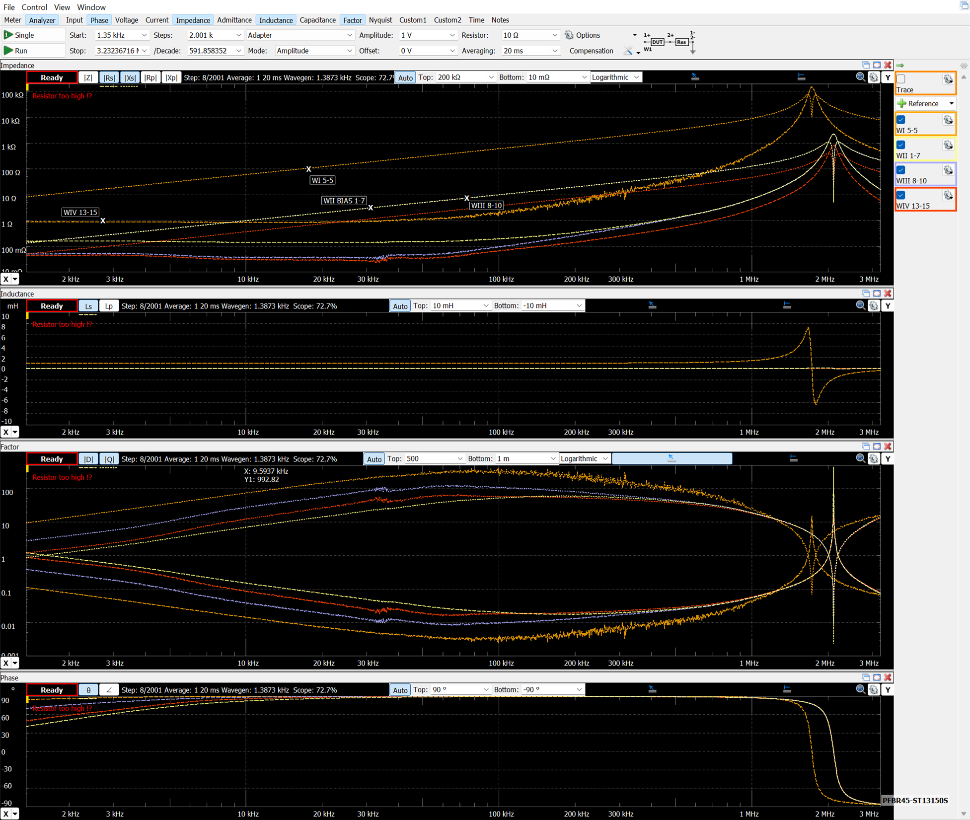
Examining Model 094932 SP-E 20/6 Flyback Transformer
Model 094932 SP-E 20/6 Flyback Transformer: Buy Now
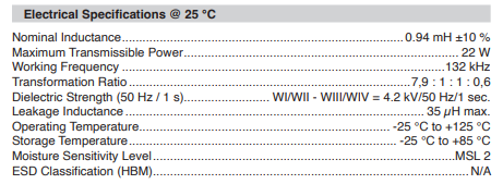
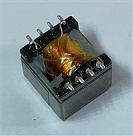
Model 094932 SP-E 20/6 Flyback Transformer

Amplitude 0.1V, Resistor 10Ω Frequency 132 kHz
| WI 1 5-3 | WII 1-7 | WIII 8-10 | WIV 13-15 | |
| Ls Series Inductance | 829.661863 uH | 15.0554441 uH | 15.2006369 uH | 5.69572509 uH |
| |Z| Impedance | 688.746087 Ω | 12.4885068 Ω | 12.6077117 Ω | 4.72459588 Ω |
| Rs Series Resistance | 29.7021179 Ω | 212.948263 mΩ | 123.043942 mΩ | 79.7294894 mΩ |
| Xs Series Reactance | 688.105338 Ω | 12.4866912 Ω | 12.6071113 Ω | 4.7239231 Ω |
| ∠ Input Phase | 86.7182489 ° | 50.7327174 ° | 51.2496131 ° | 25.1144299 ° |
| θ Phase | 87.5283577 ° | 89.0229714 ° | 89.4408176 ° | 89.0330644 ° |
| D Dissipation | 0.043165074 | 0.017054019 | 0.009759884 | 0.016877813 |
| Q Quality | 23.1668778 | 58.637206 | 102.460235 | 59.2493836 |
Frequency response of the individual wirings:
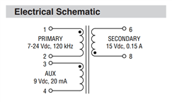
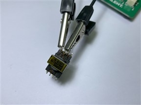
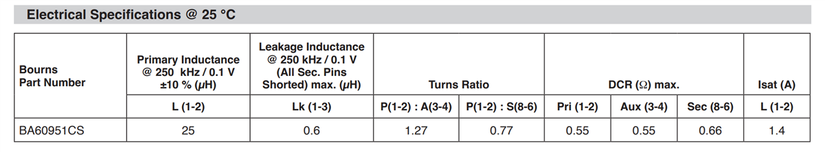
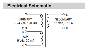
Examining BA60951CS – Flyback Transformer
BA60951CS – Flyback Transformer Buy Now
FEATURES: Isolated flyback transformer, Designed for isolated power supplies operating at 120kHz, 800V working voltage, Basic insulation, 2.25W of output power
APPLICATIONS: Electric vehicles requiring high isolation voltage, Battery management systems, Flyback controller ICs,SPECIFICATIONS 25µH at 250kHz/0.1V primary inductors, 8mm minimum creepage distance, -40°C to +155°C operating temperature range
Amplitude 0.1V, Resistor 10Ω Frequency 250 kHz
| Primary 1-2 | AUX1 1-4 | Secondary 6-8 | |
| Ls Series Inductance | 26.0613937 uH | 16.3672187 uH | 43.7414393 uH |
| |Z| Impedance | 40.9427379 Ω | 25.7238413 Ω | 68.7185145 Ω |
| Rs Series Resistance | 676.93365 mΩ | 856.842683 mΩ | 1.1499414 Ω |
| Xs Series Reactance | 40.9371414 Ω | 25.709567 Ω | 68.7088922 Ω |
| ∠ Input Phase | 75.4186898 ° | 67.1397423 ° | 80.8203976 ° |
| θ Phase | 89.0526474 ° | 88.0911656 ° | 89.0411629 ° |
| D Dissipation | 0.016535929 | 0.033327776 | 0.016736428 |
| Q Quality | 60.474378 | 30.0050026 | 59.7499076 |
Frequency response of the individual wirings:
Bourns PFBR45 Power Line Communication Transformers
Bourns PFBR45 Power Line Communication (PLC) Transformers offer excellent transmission characteristics in a compact surface-mount housing.
The PFBR45 PLC Transformers are designed for ST Micro 8500 PLC System-on-Chip (SoC).
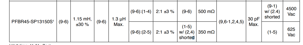
The PFBR45-ST (standard) is for functional insulation, and the PFBR45-SP (extended) is for reinforced insulation, with a working voltage of 400VDC.
These components feature a 1.5µH typical leakage inductance, a 0.45W power rating, and a -40°C to +125°C operating temperature range. Applications include smart grids, automatic meter reading, CCTV cameras, PC home networks, street lighting, and home automation.
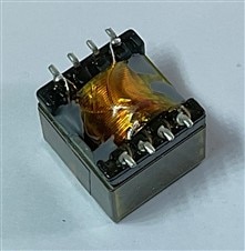
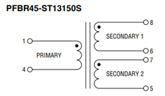
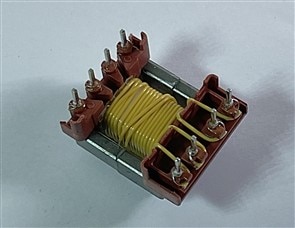
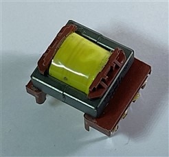
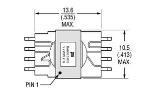
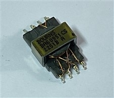
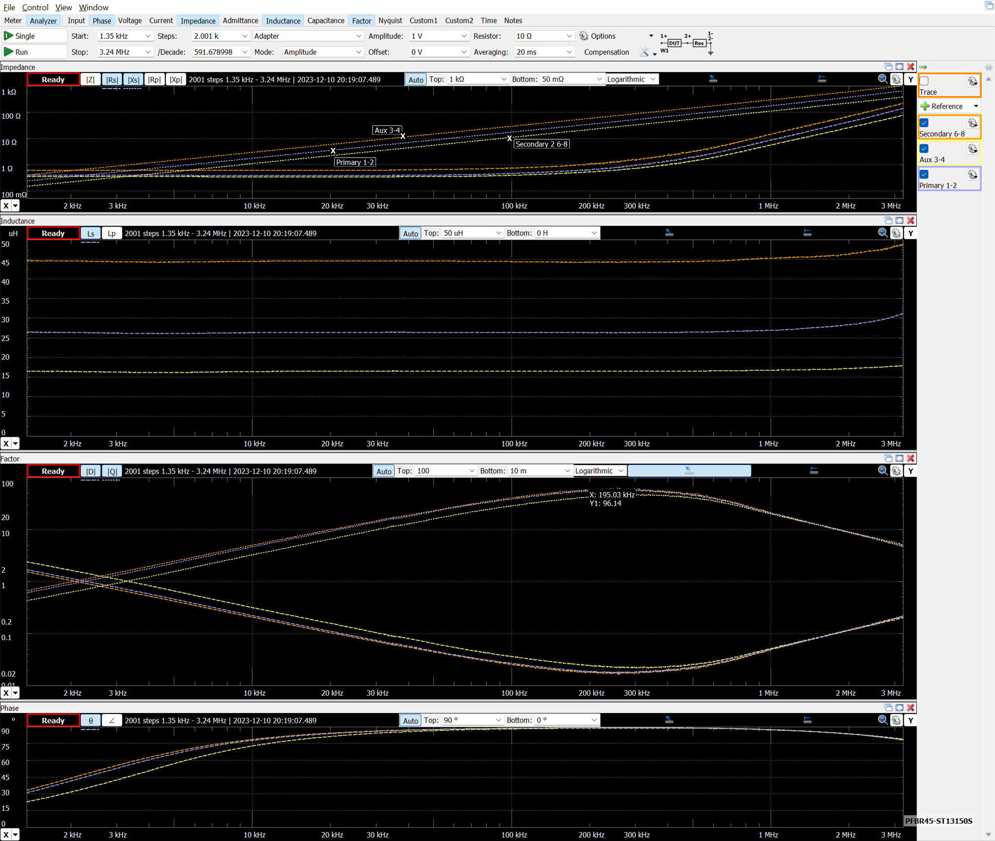
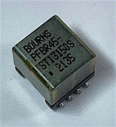
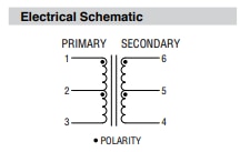
Examining PFBR45-ST13150S PLC Transformer
PFBR45-ST13150S PLC Transformer Buy Now
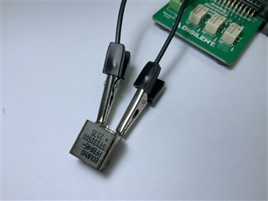

Amplitude 1V, Resistor 10Ω Frequency 100 kHz
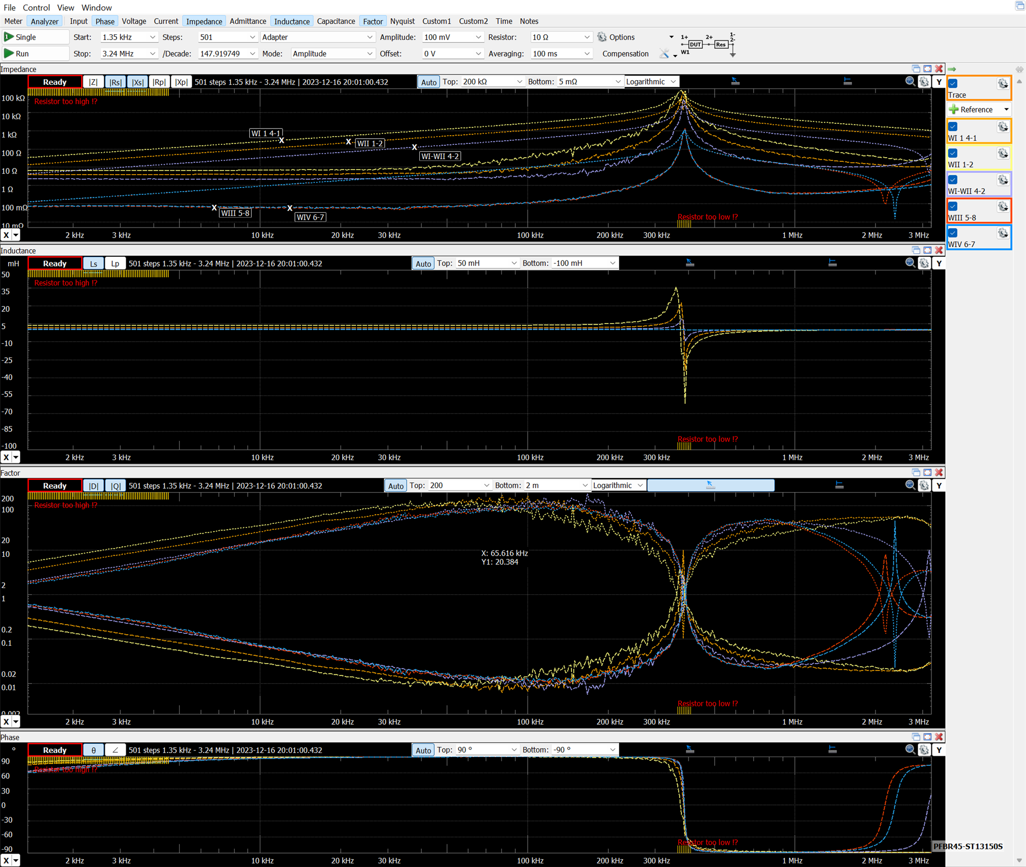
| Primary 1-4 | Secondary 1 8-6 | Secondary 2 7-5 | |
| Ls Series Inductance | 1.08967844 mH | 280.822975 uH | 281.295945 uH |
| |Z| Impedance | 684.69877 Ω | 176.470021 Ω | 176.766244 Ω |
| Rs Series Resistance | 6.78445132 Ω | 2.89464116 Ω | 2.83836654 Ω |
| Xs Series Reactance | 684.665157 Ω | 176.446279 Ω | 176.743455 Ω |
| ∠ Input Phase | 88.6111673 ° | 85.8357192 ° | 85.8608692 ° |
| θ Phase | 89.432266 ° | 89.0601341 ° | 89.0799521 ° |
| D Dissipation | 0.009909152 | 0.016405226 | 0.016059246 |
| Q Quality | 100.916806 | 60.956184 | 62.2694259 |
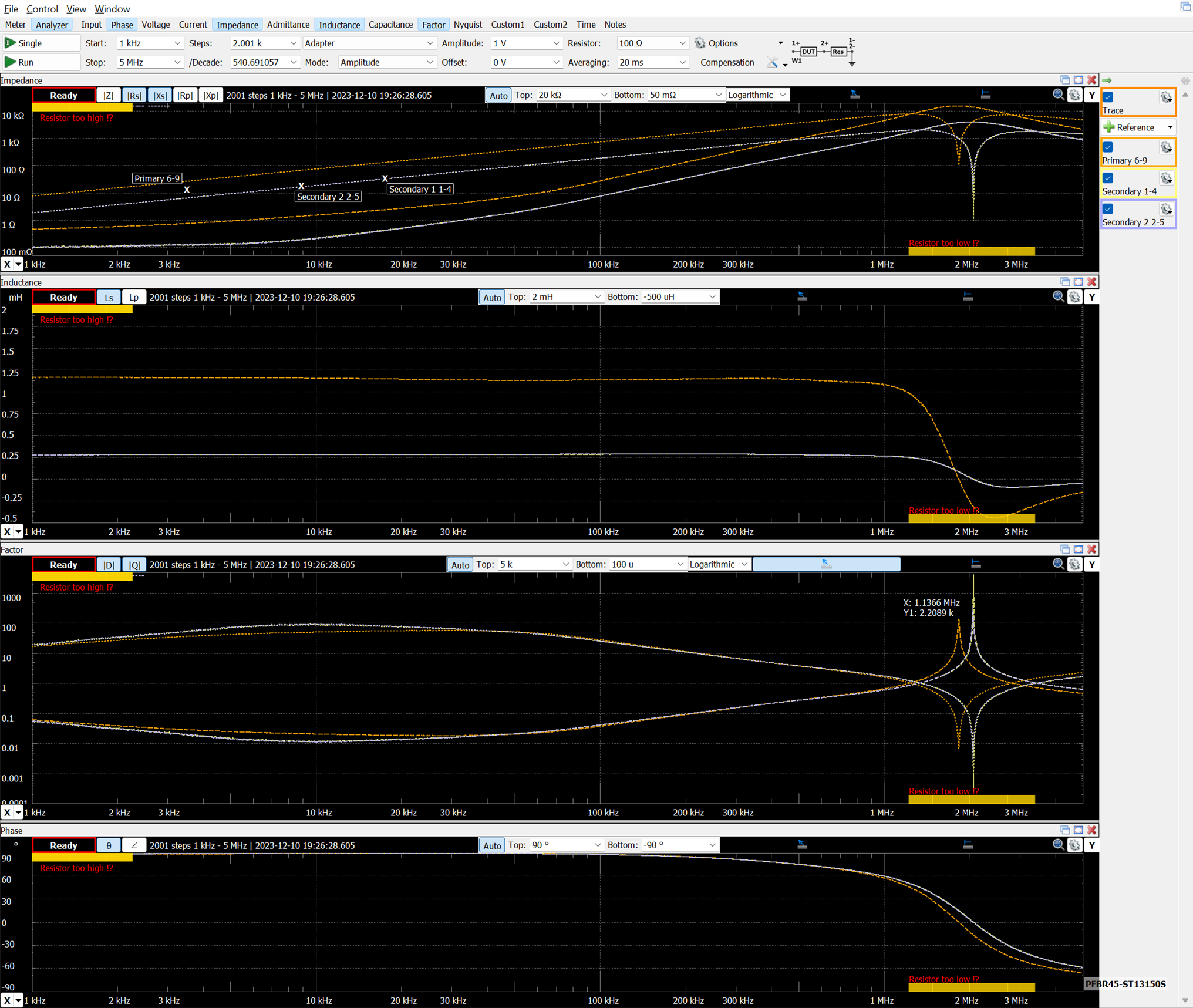
Frequency response of the individual wirings:
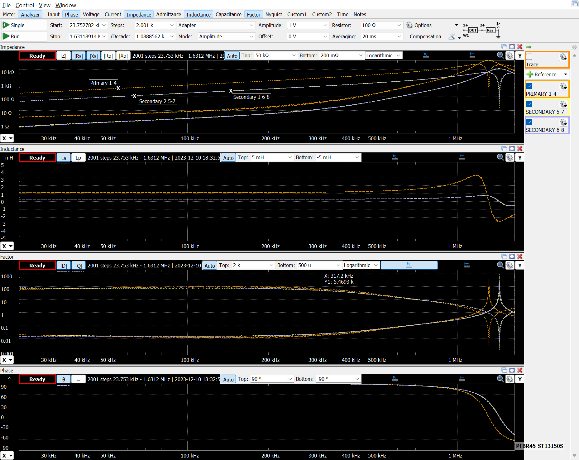
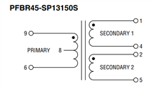
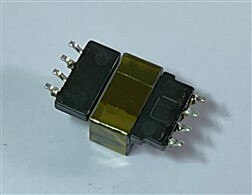
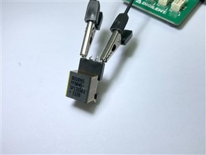
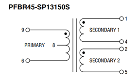
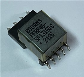
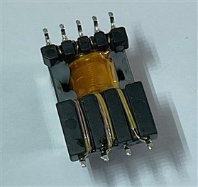
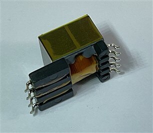
Examining PFBR45-SP13150S PLC Transformer
PFBR45-SP13150S PLC Transformer: Buy Now
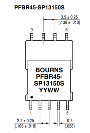
Amplitude 1V, Resistor 10Ω Frequency 100 kHz
| Primary 6-9 | Secondary 1 1-4 | Secondary 2 2-5 | |
| Ls Series Inductance | 1.11966808 mH | 281.845642 uH | 280.421545 uH |
| |Z| Impedance | 703.913293 Ω | 177.121999 Ω | 176.224541 Ω |
| Rs Series Resistance | 23.8773736 Ω | 3.42716994 Ω | 3.27789959 Ω |
| Xs Series Reactance | 703.508206 Ω | 177.08884 Ω | 176.194053 Ω |
| ∠ Input Phase | 80.1652801 ° | 10.0702897 ° | 10.0214737 ° |
| θ Phase | 88.0561026 ° | 88.891303 ° | 88.934197 ° |
| D Dissipation | 0.033940434 | 0.019352828 | 0.018603917 |
| Q Quality | 29.4633831 | 51.6720334 | 53.7521202 |
Frequency response of the individual wirings:
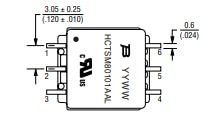
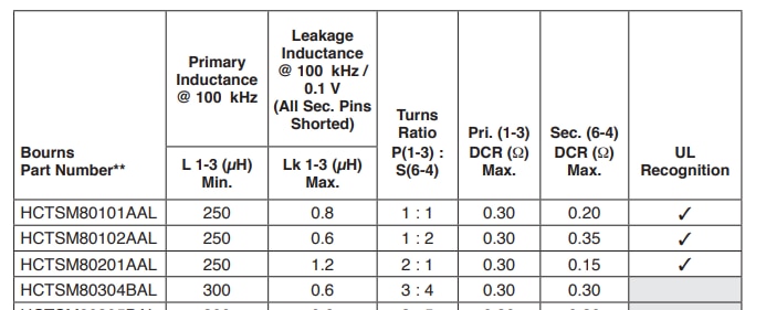
Examining HCT Series - High Clearance and Creepage Distance Transformers
BOURNS HCTSM80304BAL-E1PULSE TRANSFORMER, 3:4, 300UH Buy Now
Toroid core for high coupling and low radiation. Designed for isolation power supplies using TI SN6501 and SN6505B
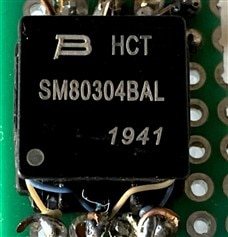
Amplitude 0.1V, Resistor 100Ω Frequency 100 kHz
| 1-3 | 4-6 | |
| Ls Series Inductance | 339.598493 uH | 590.988858 uH |
| |Z| Impedance | 213.389562 Ω | 371.341824 Ω |
| Rs Series Resistance | 2.40351115 Ω | 3.05579424 Ω |
| Xs Series Reactance | 213.376026 Ω | 371.329251 Ω |
| ∠ Input Phase | 64.4914217 ° | 74.6344769 ° |
| θ Phase | 89.3546359 ° | 89.5285043 ° |
| D Dissipation | 0.011264204 | 0.008229339 |
| Q Quality | 88.7767987 | 121.516444 |
Frequency response of the individual wirings: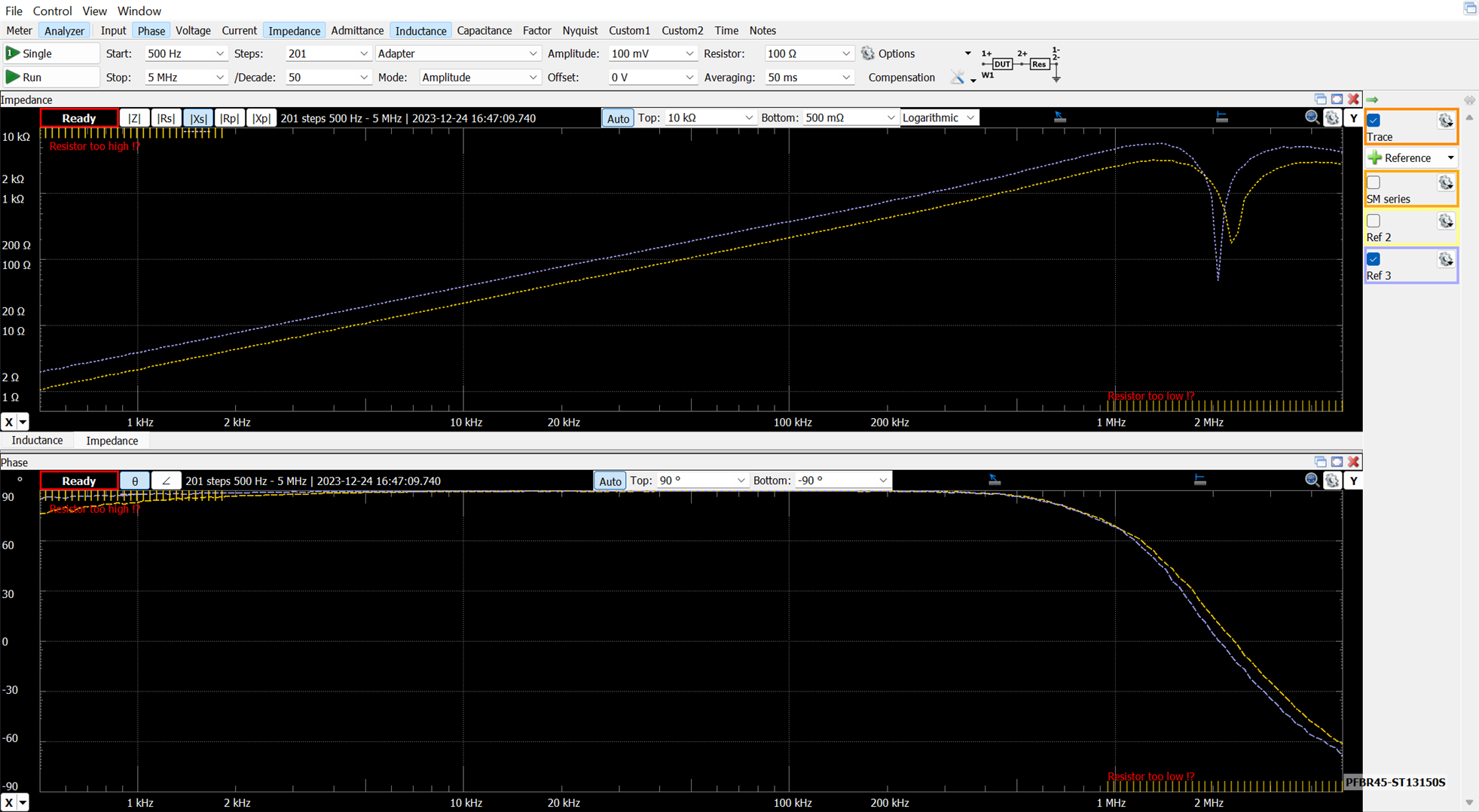
Summary and conclusions
If you have come this far you would have been able to read about some of the properties and characteristics of flyback transformers and other transformers used for isolation, transmission of power and conversion for power supplies.
The design of power transformers is a very complex subject in which designers face multiple design restrictions and which often requires trial-error refinement phases. Traditionally transformers are custom designed to meet all constraints. It is not a simple task and we must never forget safety, a bad design or using a transformer for a use for which it was not designed can cause fires or electrocution.
Magic Lightbox Blog Series
- Blog 1 - Magic Lightbox: Smart LED Dimmer Flyback Driver Project Introduction.
- Blog 2 - Magic Lightbox: Understanding Flyback Transformers. How to characterize them.
- Blog 3 - Magic Lightbox: Understanding Flyback Converters.
- Blog 4 - Magic Light Box: DC/DC Flyback Converter Testbench and LED Dimmer Driver
- Blog 5 - Magic Light Box: Building The Prototype
- Final - Magic Lightbox: Project Summary
