


Introduction
This marks my initial post introducing myself to the Experimenting with Flybacks Transformers competition, generously sponsored by Bourns and Element14. Bourns, an established American electronics company with over 70 years of experience, is dedicated to the development, manufacturing, and distribution of top-notch electronic components. Two years ago, I engaged in a similar experimenting competition, also sponsored by Bourns and Element14, which centered on various magnetic components such as line filters, RF chokes, inductors, common mode chokes, and pulse transformers.
Experimenting with Magnetics Components (year 2021)
On the Experimenting with Magnetics Components with Bourns I decided to learn about magnetic components by developing an application that interested me quite a bit, the discrimination of coins using their magnetic properties. The design led me to experiment on the magnetic properties of coins, on Eddy currents, on magnetic insulation and magnetic flux losses. I learned how to make oscillators with magnetic components, used EMI filters and pulse transformers to galvanically isolate two stages of the circuit. It was a fascinating learning journey of which I have very fond memories.
Image from my participation in the 2021 Experimenting with Magnetics Components Competition: Smart Coin Sorter by Inductive Sensing
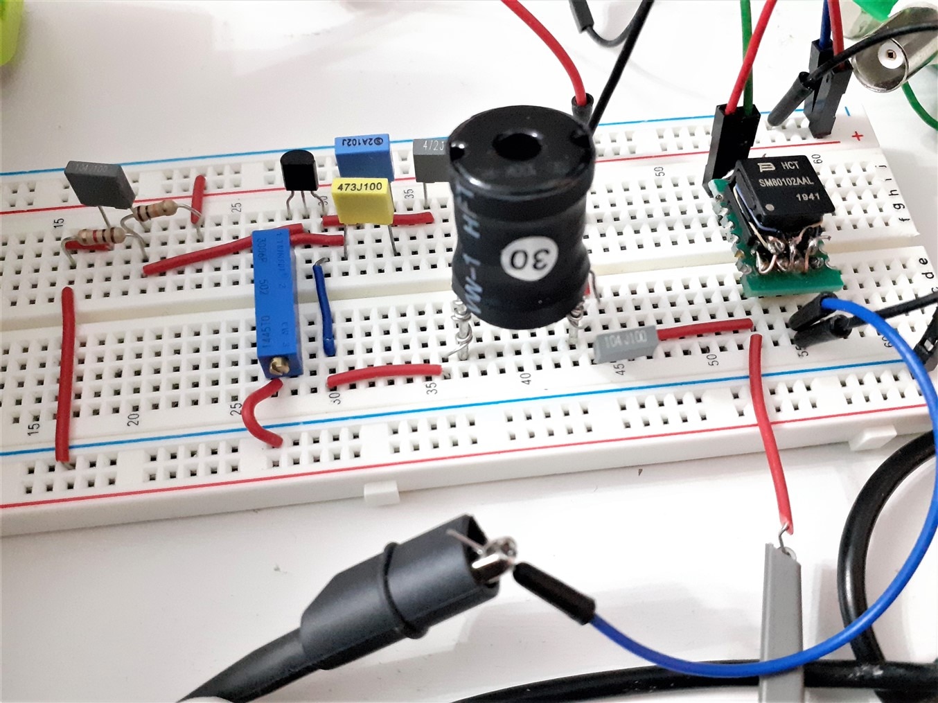
2021 Experimenting with Magnetics Components: Experimenting with BJT C-B Colpitts Oscillators
Power electronics. Experimenting with Flyback Transformers
This time I participate in the Experimenting with Flyback Transformers challenge with the same enthusiasm and desire to learn. Power electronics have always scared me quite a bit. My experiments as a teenager were not very successful. I remember leaving my entire building without electricity on one occasion by repairing and short-circuiting with a screwdriver a power supply that I forgot to unplug. On another occasion I painted the ceiling of my room bluish green with a filter capacitor that exploded when placed with the polarity reversed. I have always found it difficult to understand why the positive terminal is called the anode and the negative terminal the cathode, it goes against my understanding like many other conventions in electronics.
In this edition of the competition I want to follow a work scheme similar to when I participated in the previous experimentation challenge with magnetic components. Consider an application, the Magic Lightbox, explore designs and learn as I go to solve the problems I encounter. As I research I am discovering how difficult it is to work with flyback transformers so it is going to be an adventure into the unknown, I hope to be able to produce blogs that are interesting with what I assimilate.
What's in the Experiment with Flyback Transformers kit?
In the image below you can see all the components supplied in the experimentation kit for this Experimenting with Flyback Transformers Challenge

Experimenting with Flyback Transformers Kit
The kit contains magnetic components from three important groups:
- Two Power Line Communications (PLC) Transformers,
- eight SMPS Flyback Transformers for use in Switched Mode Power Supplies (SMPS)
- and two EMC FIlter Chokes.
The challenge presentation page indicated that two gate driving transformers were supplied but they are two power line communications (PLC) coupling circuit transformers.
Image top row from left to right:
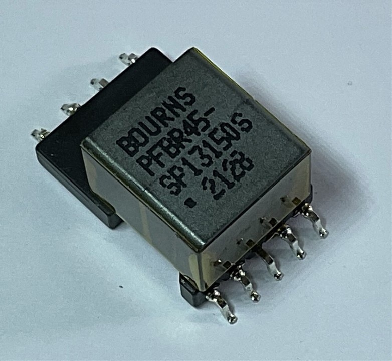
- PFBR45-ST13150S PLC Transformer, 1MH, 2KV Buy Now
- PFBR45-SP13150S PLC Transformer, 1.15MH, 4.5KV Buy Now
- BA60951CS XFMR, SMPS, FLYBACK, 2.5KV Buy Now
- 094929 SMPS Transformer, Flyback, 900 mA, 132kHz, 22 W, 85V to 265V Buy Now
Middle row from left to right:
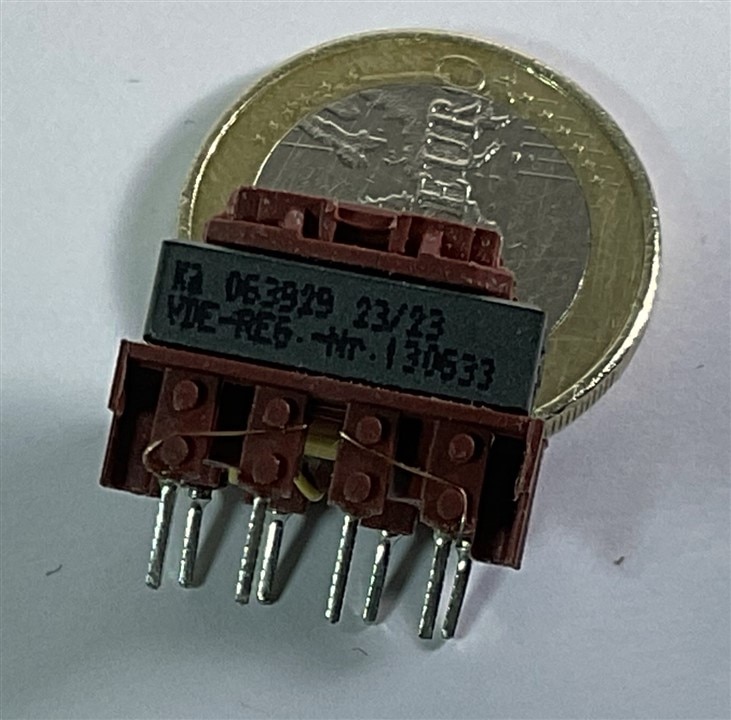
- 063929 SMPS Transformer, Flyback, 250 mA, 44kHz to 132kHz, 4 W, 85V to 265V Buy Now
- 063932 SMPS Transformer, Flyback, 250 mA, 44kHz to 132kHz, 6 W, 85V to 265V Buy Now
- 093830 SMPS Transformer, Flyback, 650 mA, 132kHz, 8 W, 85V to 265V Buy Now
- 063934 SMPS Transformer, Flyback, 370 mA, 44kHz to 132kHz, 9 W, 85V to 265V Buy Now
Button row from left to right:
- 094931 SMPS Transformer, Flyback, 1.8 A, 66kHz to 132kHz, 22 W, 85V to 265V Buy Now
- 094932 SMPS Transformer, Flyback, 1.2 A, 132kHz, 22 W, 85V to 265V Buy Now
- 071923 Choke, Common Mode, 0.28 A, 22 mH, Through Hole Buy Now
- 093267 Choke, Common Mode, 0.5 A, 27 mH, Through Hole Buy Now
What is a Gate Drive transformer?
The kit does not contain gate drive transformers but PLC transformers, but what are a gate drive transformers?
Gate drive transformers are used to deliver the controlling gate-voltage pulses between the drain and source of a MOSFET, while providing isolation between the MOSFET and the controlling drive circuit. A gate drive transformer isolates the controlling gate-drive circuit from the switch node when driving the MOSFET gate and may also scale the output voltage via an appropriate primary-to-secondary turns ratio.
A gate-drive transformer is needed in a Switched Mode Power Supply (SMPS) to control the timing of the circuit. These devices provide electrical pulses for turning on and off semiconductors, such as high-voltage power MOSFETS or IGBTs. They also are used for voltage isolation and impedance matching. Any coupled inductor or transformer can be used as a gate drive transformer if it has the inductance, turns ratio, leakage inductance, isolation, and volt-time rating required by the application.
What is a PLC transformer?
Power line communication (PLC) carries data on the power line. PLC transformers are designed for detection and transmission of wideband low voltage differential data and communication signals (LVDS). The PLC transformer provides galvanic isolation between the PLC modem and the power line, helping separate the PLC from the AC mains. A key characteristic of these transformers is their minimal insertion loss, which reduces signal distortion and attenuation.

What is a Switched Mode Power Supply (SMPS)?
A switched-mode power supply (SMPS), also called switching-mode power supply, switch-mode power supply, switched power supply, or simply switcher, is an electronic power supply that incorporates a switching regulator to convert electrical power efficiently.


A generic power supply for charging mobile batteries is shown that uses the ubiquitous flyback converter topology.
What is a SMPS Flyback transformer?
A flyback transformer is actually a coupled inductor with a gapped core. Flyback transformers are used to provide voltage transformation and circuit isolation in Flyback converters. During each cycle, when the input voltage is applied to the primary winding, most of the energy is stored in the core gap. It is then transferred to the secondary winding to provide power to the load.

What is a Common Mode Choke?
A common mode choke is an electrical filter that blocks high frequency noise common to two or more data or power lines while allowing the desired DC or low-frequency signal to pass. Common mode (CM) noise current is typically radiated from sources such as unwanted radio signals, unshielded electronics, inverters and motors. Left unfiltered, this noise presents interference problems in electronics and electrical circuits.


In the image Bourns Common Mode Choke, 12.5 uH from the 2021 Experimenting with Magnetics Components with Bourns.
What is an Electromagnetic Compatibility (EMC) Filter?
EMC (Electromagnetic Compatibility) filters are used to ensure that electrical and electronic equipment does not generate, or is not affected by, electromagnetic disturbance. In Europe we have (EMC) Directive 2014/30/EU, in North America they have FCC Part 15, and military applications have MIL specs, Other regions may have different regulations.


What is Magic Lightbox?
Magic Lightbox is a project that aims to solve a lighting problem in photography. Magic Lightbox is a lighting box for small objects that will try to find optimal contrast when taking a photograph of a small electronic component.
The magic light box consists of two LED panels facing each other like light softboxes, as shown in the image below.

Magic Lightbox Lighting Diagram - 3D View
One of the softboxes has manual dimming control and the other has automatic dimming control using a switched dimming circuit which will use a flyback converter topology.
What is a Flyback Converter?
The flyback converter is a DC to DC converter with galvanic isolation between input and output. It has the same structure as a buck-boost converter with two coupled coils instead of a single coil. The flyback converter uses a flyback transformer, a type of magnetic component that was initially designed to generate high-voltage sawtooth signals at a relatively high frequency. In modern applications, it is used extensively in switched-mode power supplies. Although it is called a transformer, it is not exactly a transformer. A transformer does not store more than a minimal part of the energy while it works, unlike the flyback transformer which is designed with an air gapped magnetic core that allows the storage of a large part of the energy.
Evaluating Image Quality. Calculating image contrast.
To control the contrast, the Magic Light Box will gradually vary the lighting of a softbox built with LEDs and will adjust the lighting level to the level that provides the best contrast. To do this, it will use digital image processing, evaluating different aspects of the image, such as the intensity of the edges or the number of corners found or the shape of various tonal histograms of the photograph.
Simulation of the variation of the light intensity of the LED panel controlled by our intelligent driver. In the video you can see how the histograms vary when the light intensity of one of the LED panels increases or decreases.
We can apply various types of indices and algorithms to evaluate the quality of our image. Our definition of quality is that the image has the maximum separation of details. The objective is not an artistic photo but a photo that allows us to clearly see the characteristics of the electronic component to be photographed.
Evaluating contrast by edge detection.
Edge and corner detection algorithms can help us distinguish between a photo with more "quality" than another. See the example in the following photos applying the Sobel algorithm for edge detection.


Application of the Sobel edge detection algorithm for image contrast evaluation.
Lighting diagram
For simplicity, one of the panels will be set to a certain light intensity manually. The other Panel is a controllable panel using a switched converter circuit with current control using a PWM signal.
A camera will continuously take images from the same point from which the final photo will be obtained. Using a PID controller and an algorithm to scan possible contrasts, the intensity of one of the LED panels will vary.
|
Top View |
Side View |


Magic Lightbox Lighting Diagram
High Level System Diagram
The Magic Lightbox system consists of:
- A chassis
- Two LED panels.
- One microcontroller and/or FPGA
- One Camera sensor.
- Adjustable Constant-Current Switched Mode Flyback Controller Using Analog to Digital Current Feedback
Adjustable Constant-Current Switched Mode Flyback Controller
Constant-Current Flyback Controller Using Analog to Digital Current Feedback

Explanation of the diagram blocks:
- PID controller: A PID controller or regulator is a system that allows controlling a closed-loop system so that it reaches the desired output state. The PID controller is composed of three elements that provide Proportional, Integral and Derivative action. The PID controller calculates the difference between our actual current versus the desired current. The proportional value depends on the current error, the integral depends on past errors, and the derivative is a prediction of future errors.
- PWM Controller: The Pulse Width Modulation (PWM) allows us to modify the duty cycle of a periodic signal that controls the amount of energy that will be stored in the Flyback transformer.
- Flyback Converter: The flyback converter is a DC to DC converter with galvanic isolation between input and output. When the switch is activated (top diagram), the primary coil is connected directly to the power source. This causes an increase in the magnetic flux in the core. The voltage on the secondary is negative, so the diode is in reverse (blocked). The output capacitor is the only one that provides power to the load. When the switch is open the energy stored in the magnetic core is transferred to the LEDs array and the output capacitor.
- Current Probe: The current probe allows us to measure current without being connected in series. It converts the current into a voltage that we will measure using an analog to digital converter.
- Computer Vision Controller: The computer vision controller module will analyze the contrast of the image and propose a target current value for the PID controller to follow.
- Camera: This sensor captures light and converts it into an electrical signal that is then processed to form a digital image.
PLC extension: Controlling the Lightbox over the power line.
Although it does not make much practical sense to control this light box over the power line, I have proposed it as an exercise to practically understand how communications over the power line work.
To make things easier, communication is one-way from the control unit to the light box and the commands will be reduced to raising or lowering the intensity of the light.
The diagram shows a high-level block diagram of the PLC communication system.

PLC transformers are essential for the coupling circuits of the data signal with the power line signal.
Communication will be carried out using a very simple scheme generally called OOK. On–off keying (OOK) denotes the simplest form of amplitude-shift keying (ASK) modulation that represents digital data as the presence or absence of a carrier wave. In its simplest form, the presence of a carrier for a specific duration represents a binary one, while its absence for the same duration represents a binary zero. I will study communications with the X-10 protocol
What is the X-10 protocol?
X10 is a low-bandwidth communications protocol for remote control of electrical devices that uses the pre-existing power line (220V or 110V AC) to transmit control signals between home automation (home automation) equipment in digital format. https://en.wikipedia.org/wiki/X10_(industry_standard)
X10 control signals are based on the transmission of bursts of RF pulses (120 kHz) representing digital information. These pulses are synchronized at the zero crossing of the mains signal (50 Hz or 60 Hz). With the presence of a pulse in a half cycle and its absence in the following half cycle, a logical '1' is represented and conversely a '0' is represented. In turn, each order is transmitted twice, meaning that all transmitted information has quadruple redundancy. Each order involves 11 network cycles (220 ms for 50 Hz and 183.33, for 60 Hz).
The way forward from now on
I have presented the application with which I intend to learn more about flyback transformers and the rest of the magnetic components received with the kit around a unique application, a smart light box for photographing small electronic components.
- I will begin the challenge by learning to characterize flyback transformers,
- I will learn the theory behind switched converters with special emphasis on those galvanically isolated by transformer,
- I will learn how to design flyback converters using commercial drivers and online tools,
- I will build a circuit with LED light dimming control,
- and explore the possibilities of data communication over the power line.
Thanks for getting here.
Magic Lightbox Blog Series
- Blog 1 - Magic Lightbox: Smart LED Dimmer Flyback Driver Project Introduction.
- Blog 2 - Magic Lightbox: Understanding Flyback Transformers. How to characterize them.
- Blog 3 - Magic Lightbox: Understanding Flyback Converters.
- Blog 4 - Magic Light Box: DC/DC Flyback Converter Testbench and LED Dimmer Driver
- Blog 5 - Magic Light Box: Building The Prototype
- Final - Magic Lightbox: Project Summary
Top Comments