


Table of Contents
- Introduction
- Project Vision
- Project Components
- TM251MESE PLC
- HMIST6200 HMI
- ABLM1A24025 Power Supply 24VDC 2.5A
- ZBRN2 Harmony Hub (Wireless Serial Gateway)
- ZBRRH Wireless Receiver
- ZBRT2 Transmitter
- ZBRA2 External Antenna
- ZBRA1 Relay Antenna
- 1 - ZB5AK1233 Wireless Selector Switch
- 2 - ZB5AW333 Push button
- 3 - ZB5AZ009 Collar
- 4 - 70-782D8-1A Relay Socket
- 782XBXM4L-24D Power Relay
- ZBRV1 Visual Feedback
- TM3DM8R Discrete IO Module
- Project Execution
- Project Completion
- Conclusion
- Stretch Goal
- Other Blogs
Introduction
First I would like to thank Schneider Electric and element14 for selecting me to participate in the Experimenting with Industrial Automation Design Challenge. This Design Challenge has really been a "bucket list" experience for me. I have always wanted to use a real Industrial Programmable Logic Controller (PLC) in an application that provides a genuine benefit or upgraded capability. Sounds super nerdy. Well... yes. Thank you. Adding the Human Machine Interface (HMI)... that's just icing on the cake. And wireless switches and outputs?! I don't know if the phrase "geeking" is still acceptable, but I am definitely geeking over this. Not sorry one bit.
If you read some of the other blogs I did during this Design Challenge, please forgive me for repeating myself. I promise that it won't be an exact copy of previous blogs. For those that did not read those blogs, I will provide a list of them at the end of this blog.
Project Vision
The purpose of this project is to turn on a roof mounted exhaust fan to extract engine exhaust and heat from my training bay. Those are natural gas fueled generators.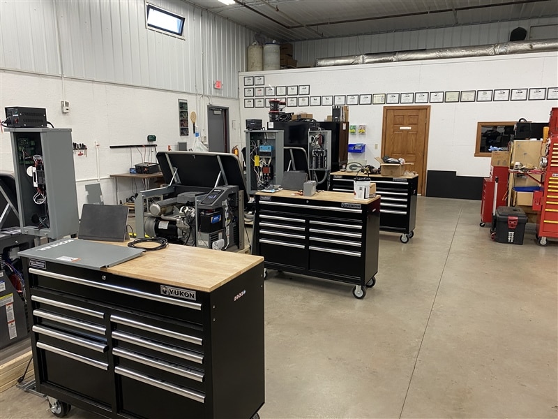
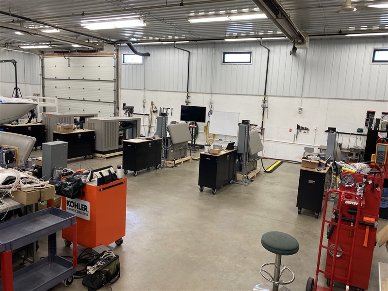
In addition to the engines that we (work) run for training, we also have a bank of Bitcoin miners that generate a surprisingly large amount of heat.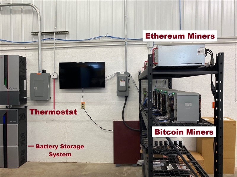
We use that heat during the Winter to warm the Training Bay and defer the use the natural gas radiant heaters. At the beginning of this Design Challenge, this system used a thermostat from the local hardware store and a Raspberry Pi Pico to control the exhaust fan and, thus, the heat in the Training Bay. Pi Pico in Industrial Fan Control
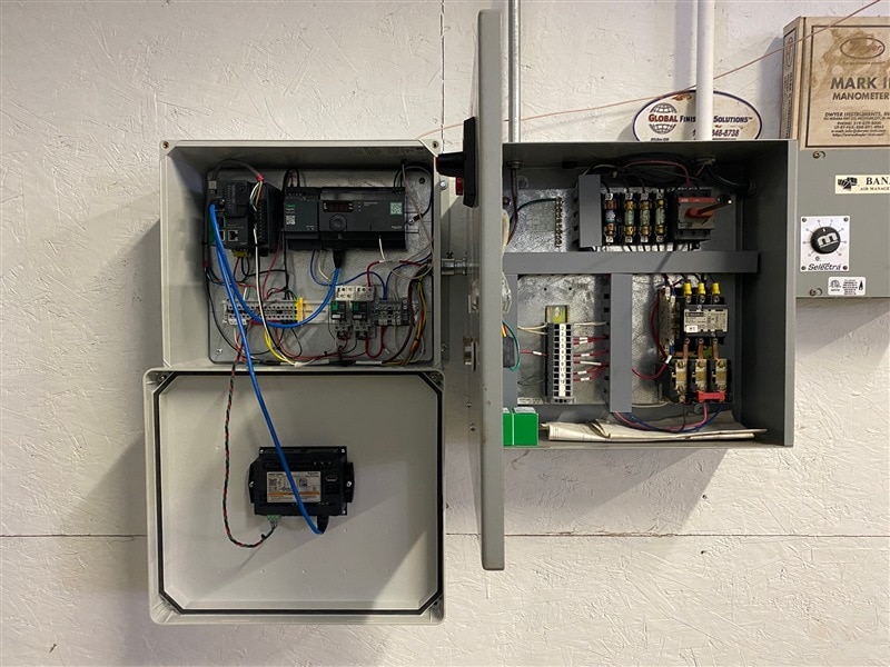
While we do not run the engines even weekly, when we do run them - it would be nice to extract the carbon monoxide and other unfriendly gasses. But... the exhaust fan is in a smaller back bay and the controls are not easily accessible. We "affectionately" refer to these blocking items as "executive storage".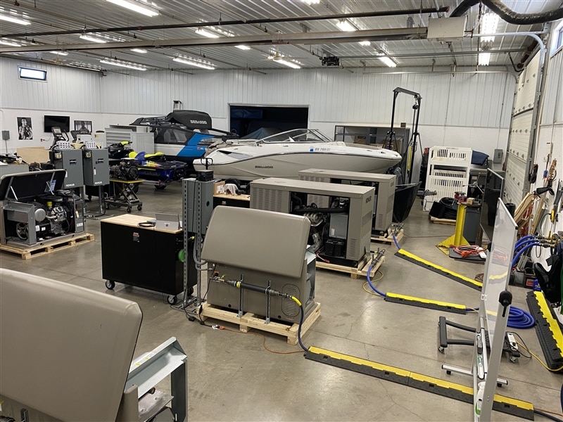
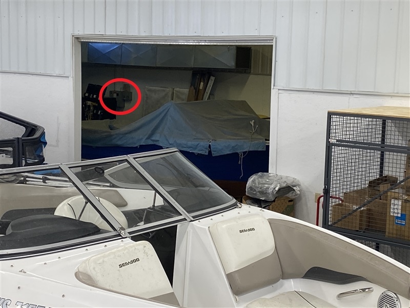
That red circle is where the fan ON/OFF control resides. Despite my best efforts, if I clear a space - miraculously - stuff appears to fill that space. Navigating to the fan controls isn't impossible - just VERY inconvenient.
So the project vision is to install a more user friendly control system that would keep the current functionality but add wireless ON/OFF fan control - so we could run the fan when the engines were running but revert back to thermostat control when they are not. I also want to add a "Ventilate Now" feature (button) that would turn the exhaust fan ON and open the large garage door should the carbon monoxide detector alarm.
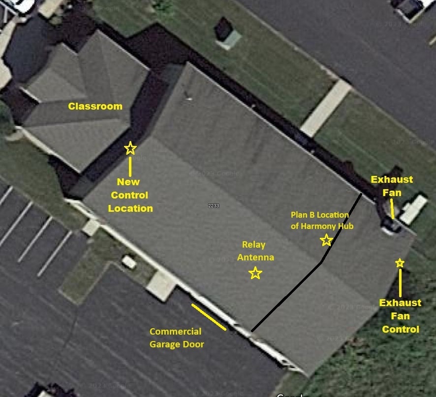
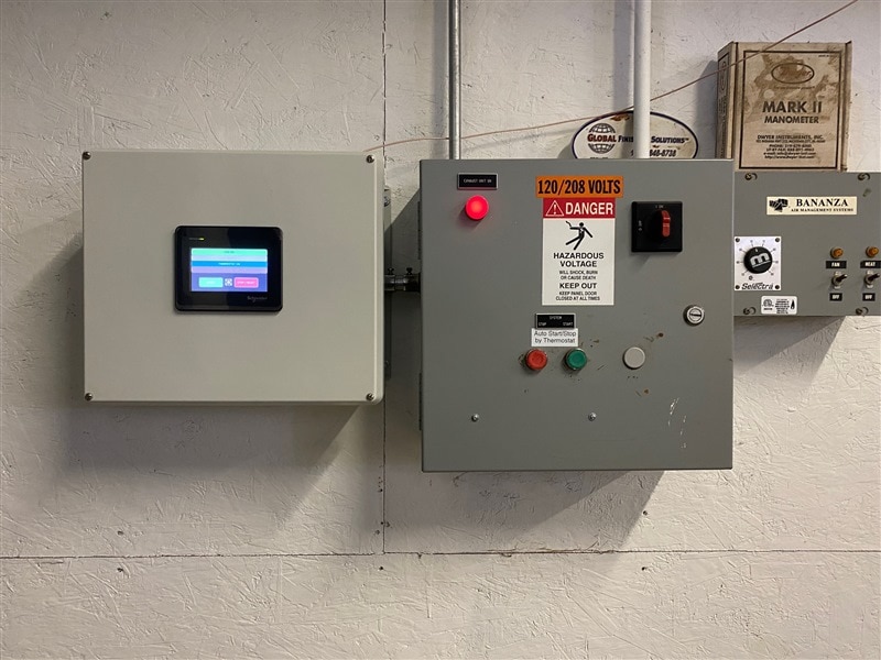
On the picture above, you can see the exhaust fan and the fan control locations on the right. The desired additional fan control location is on the left. Not including the front classroom, the building is 60 feet by 100 feet. The black line on the picture shows the approximate location of the dividing wall with the smaller opening (shown in the pictures with all the boats). You can also see the commercial garage door on a few of the picture above.
Since the Design Challenge includes wireless control, I also would like to draw your attention to the metal cladding on the upper half of the walls. It's not quite a Faraday cage, but it definitely will limit WiFi communication through that dividing wall. It has metal cladding on both sides. Thankfully, one of the devices included is a relay antenna. Lucky me.
Project Components
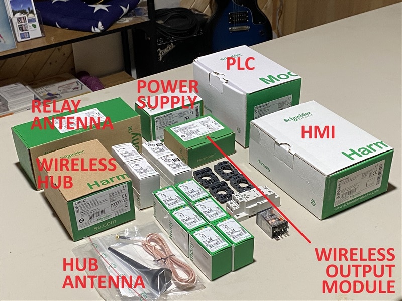
Schneider Electric and element14 really provided a comprehensive array of equipment. If you would like more information on any individual component, the device name is also a link to the web page about that item.
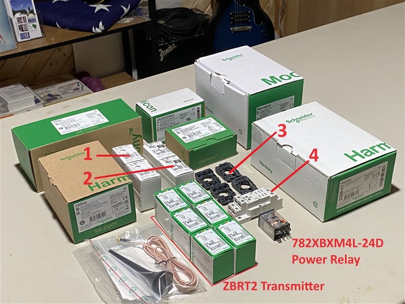
1 - Selector switch 2 - Pushbutton 3 - Switch collar 4 - Relay base
TM251MESE PLC
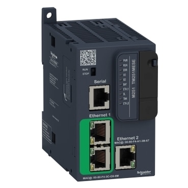
Two ethernet channels
Serial port
USB port
SD card slot
Real time clock
Web server
Expandable with snap on modules
HMIST6200 HMI
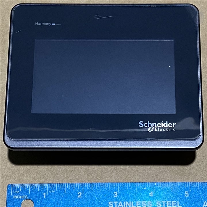
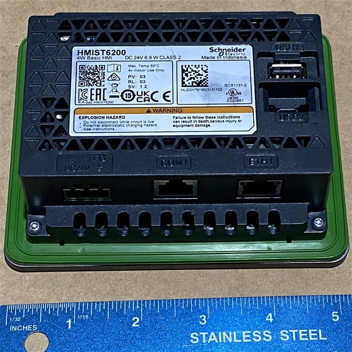
Ethernet port
Serial port
USB micro port
USB A port
ABLM1A24025 Power Supply 24VDC 2.5A
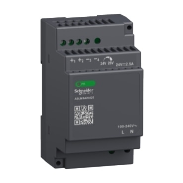
I did wind up buying a second one of these for the receiver module.
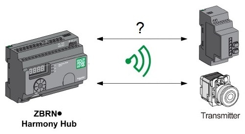
ZBRN2 Harmony Hub (Wireless Serial Gateway)
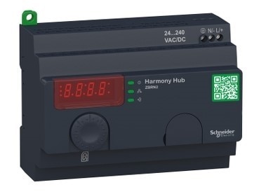
Dual serial ports
External antenna connection
24VDC to 240VAC power input
Accepts up to 60 transmitters
Communicates with up to 60 ZBRRH receiver output modules
ZBRRH Wireless Receiver
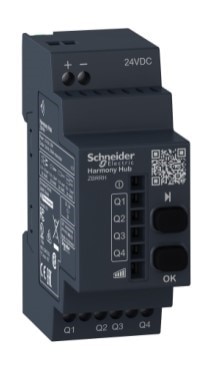
Four PNP output channels
200mA switching capability
ZBRT2 Transmitter
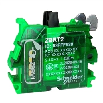
Transmits when pressed
Transmits again when released
No battery
Unique transmitter ID
The components above are the workhorses of the system but they wouldn't be complete without the other components. The numbers correspond to the picture with the numbers above.
ZBRA2 External Antenna
ZBRA1 Relay Antenna
1 - ZB5AK1233 Wireless Selector Switch
2 - ZB5AW333 Push button
3 - ZB5AZ009 Collar
4 - 70-782D8-1A Relay Socket
782XBXM4L-24D Power Relay
ZBRV1 Visual Feedback
Additional Component: In that I wanted my project to have additional physical input and output, I purchased an expansion module for the PLC.
TM3DM8R Discrete IO Module
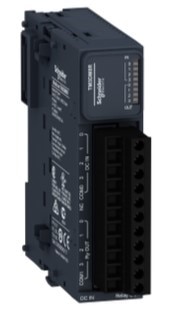
4 input
4 relay output (2A)
Isolated I/O
Project Execution
The PLC is really the heart of Industrial Automation and I couldn't wait to plug into this one. Fortunately for me, Schneider Electric has a series of training videos to familiarize you with the equipment provided for this Design Challenge.
https://www.youtube.com/playlist?list=PLFqT6GhMpgpI5lYxJBCmI8N84eV3uhbEr
That's the good news. The bad news is there is an expectation of familiarity with modern PLCs that I did not posses. This was the "challenge" part of Design Challenge for me.
Software Installation
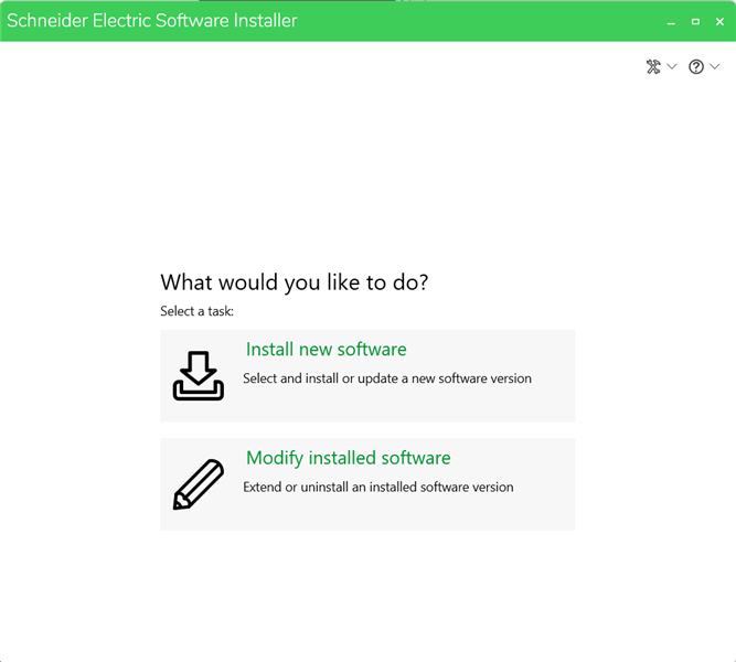
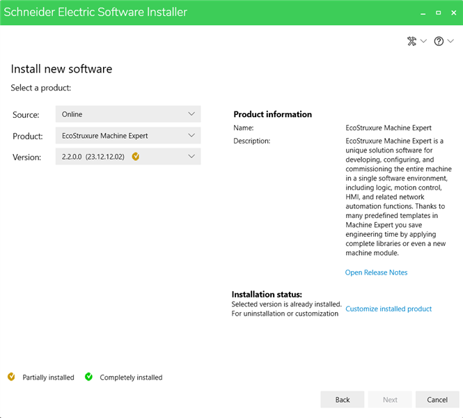
The tutorials direct you to use Schneider Electric's EcoSturuxure Machine Expert software to communicate with the TM251MESE PLC (M251). This link actually downloads the Schneider Electric Software Installer. Part of the download is a pdf instruction sheet on how to install the software.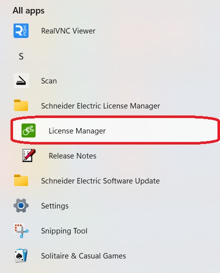
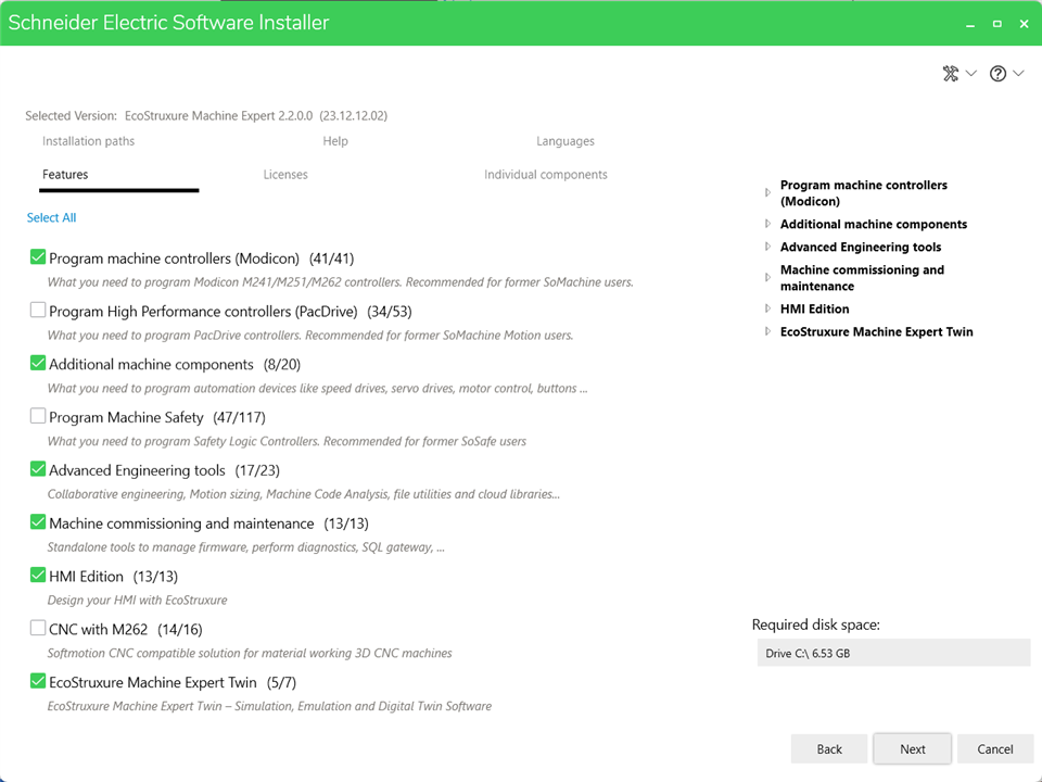
There is a selection to perform a full install, but I did not need the Safety, CNC or all the language files. There are a lot of language files.
The software has a fully functional trial mode that is good for 42 days. If there is something it does not do, I did not experience it. The 42 days was sufficient to complete the Design Challenge. My software was activated through a web portal after creating an account with Schneider Electric. I have received ZERO spam from signing up with Schneider Electric so this is a no risk account. https://secureidentity.schneider-electric.com/identity/setup/secur/RemoteAccessAuthorizationPage.apexp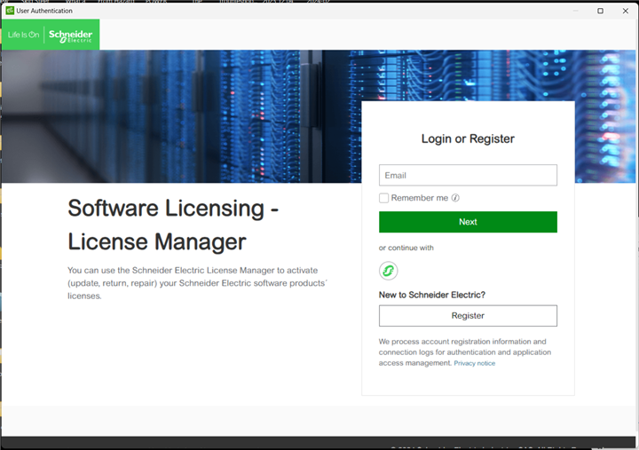
Note: EcoStruxure Machine Expert is different than the EcoStruxure Machine Expert - Basic that is used on the M221 series PLCs.
Firmware Upgrade
Initially, I had problems accessing the PLC. The default user name and password are "Administrator" but that was not working for me. Thank you to rsc for sharing how to upgrade the firmware because that allowed me to reset the security in the PLC and actually gain access. This action requires Controller Assistant - which is loaded when you select Machine Commissioning and Maintenance during the install process. Firmware upgrade instructions: https://www.se.com/us/en/faqs/FA272065/
Using EcoStruxure Machine Expert
The initial setup of the PLC using Machine Expert required the USB connection. After setting up the ethernet ports, I was also able to communicate using ethernet.
After launching the Machine Expert software and selecting New Project, you see the screen below.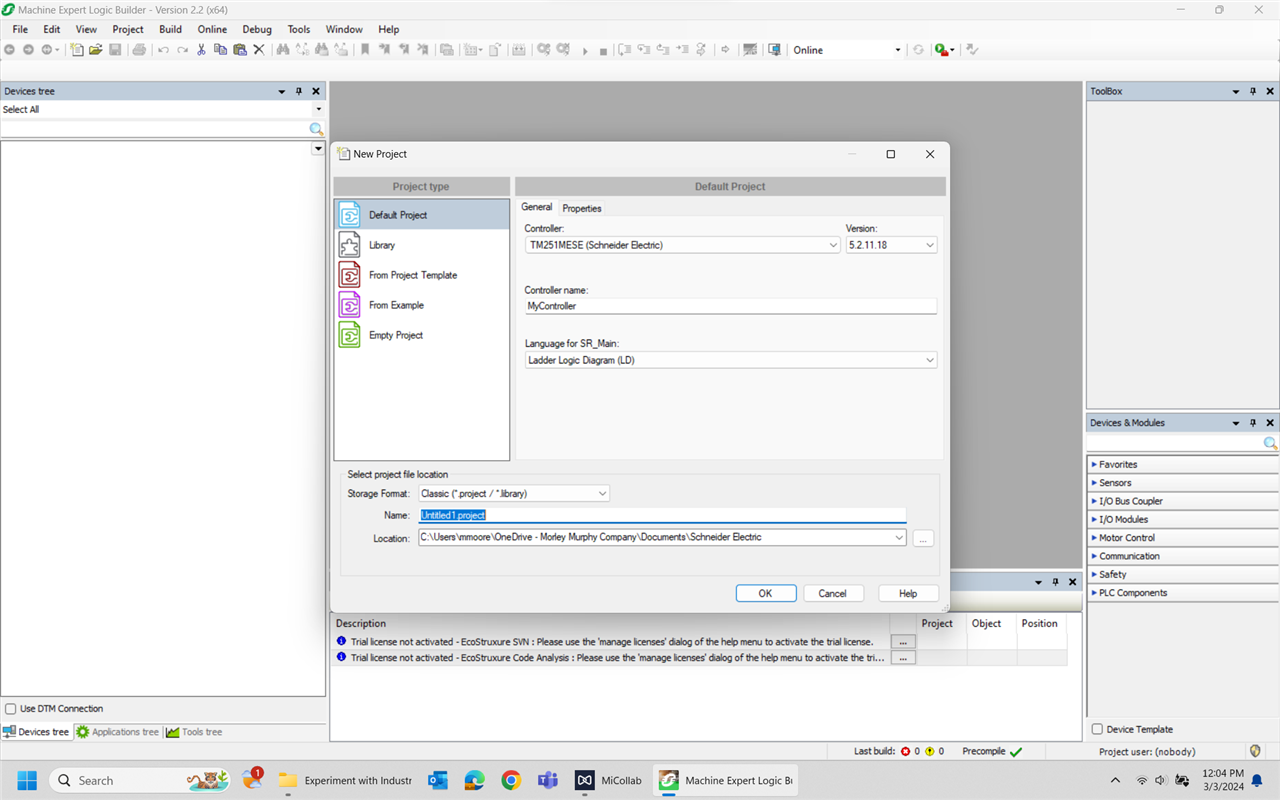
You are able to select your PLC, give it a simpler name, select your programming language and name your project. I was not able to find any difference between the Default Project and the Empty Project so I used the default. This gives you a default Device Tree - which is really hardware configuration.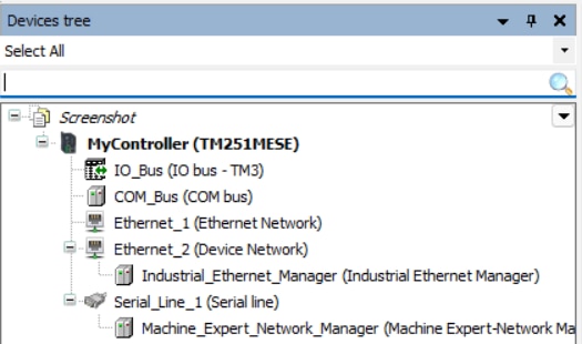
Adding the IO Module
While I had already snapped on my additional IO module, I still needed to let the PLC know that it was attached. Highlighted the IO_Bus line. Right click and selected Add Device. From the new pop-up window, select the correct module and click Add Device. The window does not auto-close. You have to close it.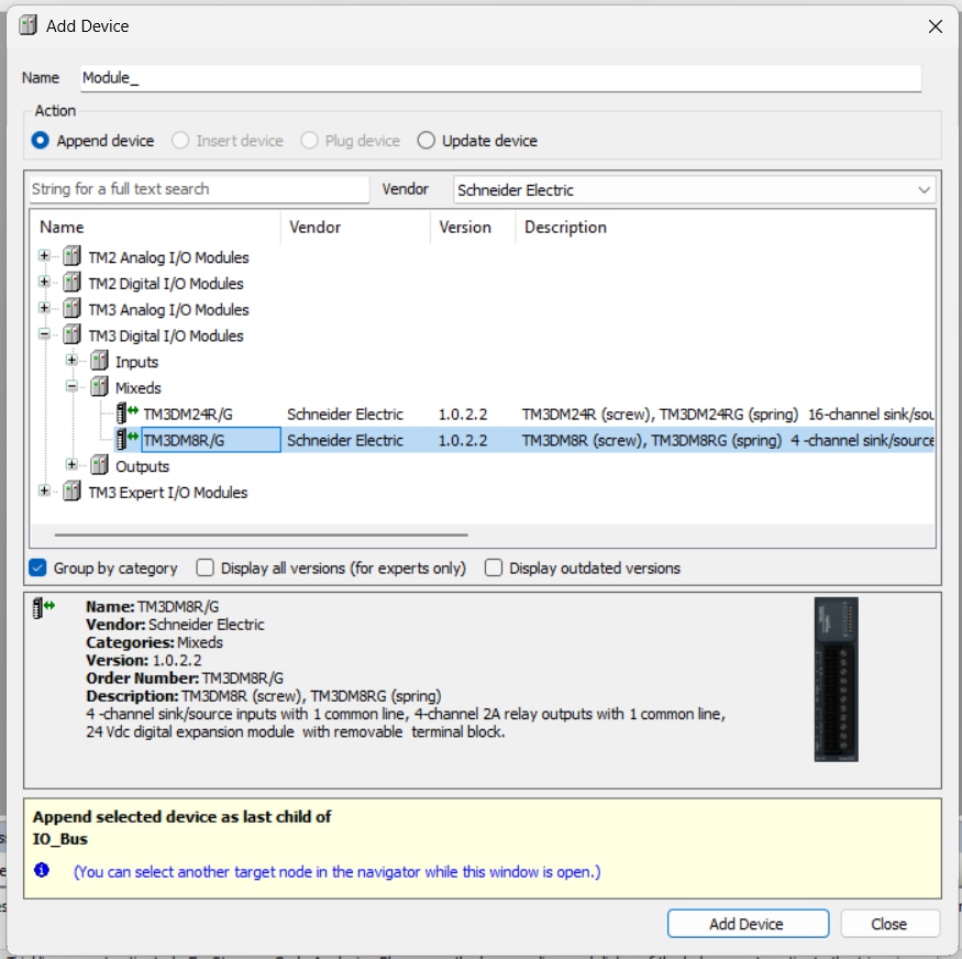
There wasn't any additional programming required with this module. I just assigned variables to the inputs and outputs and the main program was happy. I did learn that the physical inputs and outputs required an external power source to function - unlike an Arduino or Raspberry Pi. The external power source is not common to the inputs and outputs unless you wire it that way. They can be unique sources.
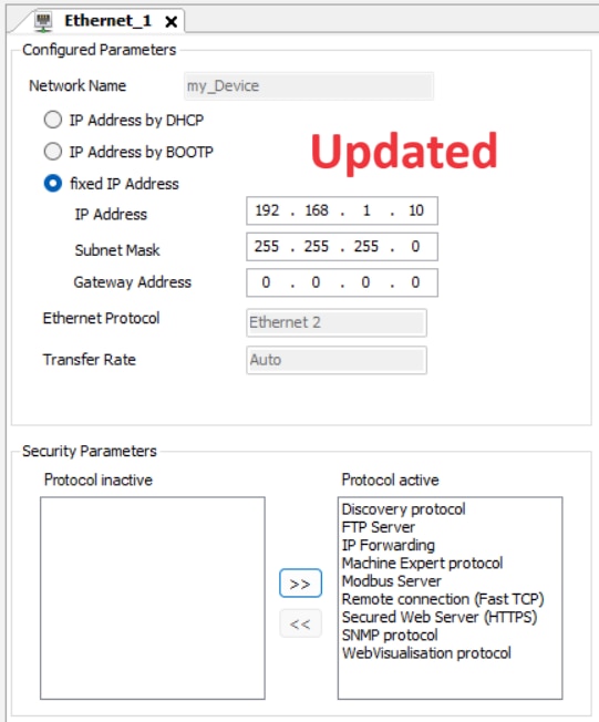
Setting the Ethernet Addresses
The TM251MESE PLC has two ethernet hubs and each needs a unique network. The ethernet setup was pretty direct. Ethernet_2 would be a 192.168.2.x or another network address.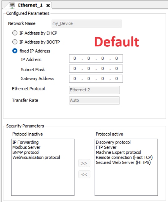
Setting the Serial Address
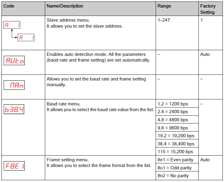
By double clicking on the Serial_Line_1, you can configure it. The Harmony Hub accepts 3 data configurations; 8E1, 8O1 and 8N2. Speeds range from 115,200 down to 1200. I chose 19,200 because that has proven to be a stable speed in my life.
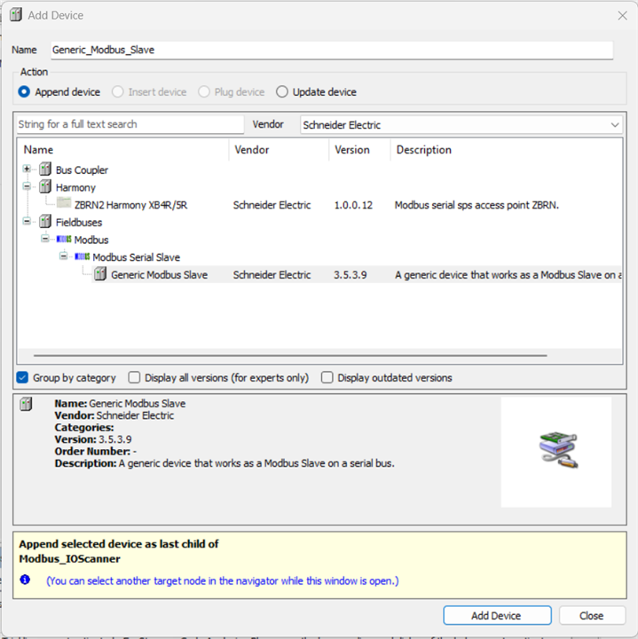
To actually communicate with the Harmony Hub, you need to delete Machine_Expert_Network_Manager and Add Device Modbus_IOScanner. The default transmission mode is RTU, but it can be changed to ASCII. Then Add Device Generic_Modbus_Slave. You could choose to add the ZBRN2 Harmony XB4R/5R instead. This choice will configure all 60 possible inputs where the generic slave can be configured for less. Either choice will need to have the output channels configured. Double clicking on the device you selected will allow you to assign the Modbus slave address. The PLC will have to communicate with the Modbus device before any further configuration can proceed. 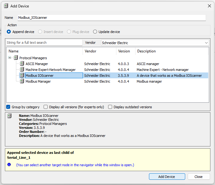
Writing the PLC Program
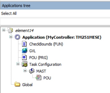
From here, we shift from the Device Tree to the Application Tree. The Default Project setup created SR_Main (PRG). This is the main program and the associated icon indicates which programming language you selected during the initial Create Project screen. Mine shows contacts which indicates ladder logic. Also note that SR_Main is also located under MAST in the Application Tree. Think of MAST as the main loop MASTer program. If you delete your program, whatever one you add in its place will need to be dragged and dropped under the MAST or it will not run. The final version of my ladder program is named POU for Programming Output Unit - which is the term the Schneider literature uses for these programs.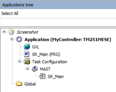
When you select the program, you get a fairly typical ladder layout. The toolbar across the top allows you to select and add the devices you need to create your logic.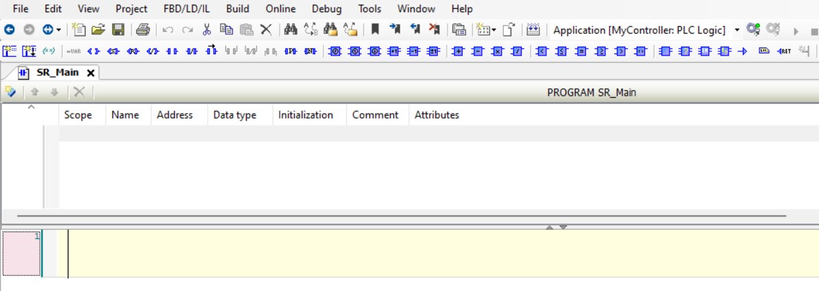
I have yet to figure out how to add the ladder logic code to the blog without locking the blog up, but here is a snippet that covers the Ventilate Now function. This section reads registers from the ZBRN2 Harmony Hub tied to the ZBRT2 transmitters (Pushbuttons). There is also a physical input from the TM3 IO module and sealing contacts - because I want the action to require a manual reset. The output closes a set of physical contacts that runs the exhaust fan motor. Additionally, there is a one second long physical contact output to a relay that signals OPEN to the garage door circuit. Finally, there is an output to drive the ZBRRH receiver module and light a lamp that indicates the system is running because the Ventilate Now button has been pushed.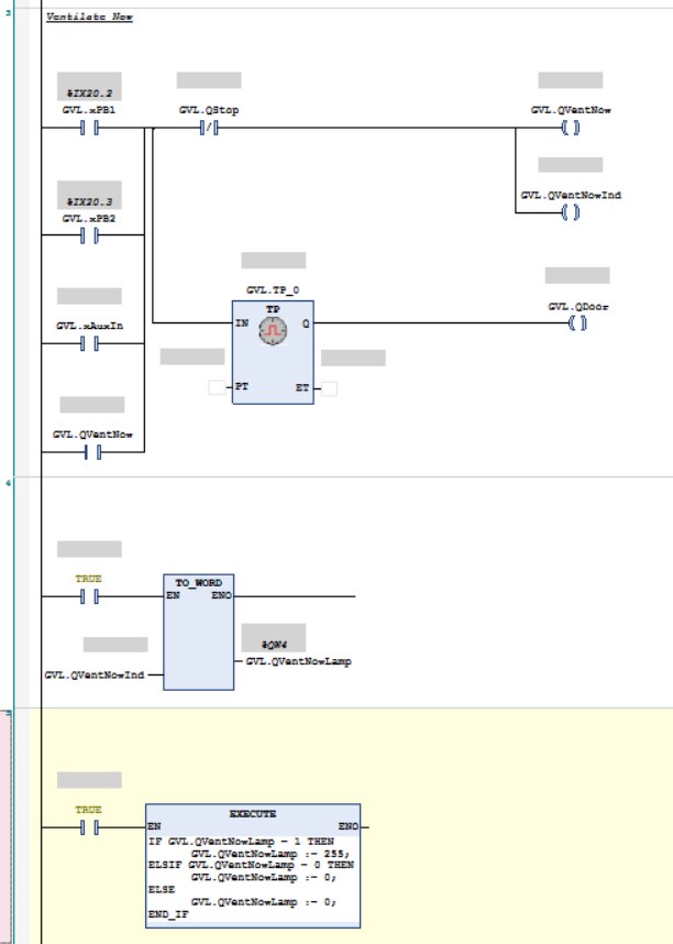
Most of this section is simple ladder logic and it functioned as it should. There were two anomalies that needed to be worked around.
The first was with the indicator output. If it were driving a lamp or other binary device, there would have been no problem, but the value needed to be converted to a 16-bit WORD for transmission to the ZBRRH receiver module. All attempts to simply convert the value caused the program to lose the connectivity to the TM3 physical output module. Again, attempting to convert GVL.QVentNowInd caused GVL.QVentNow to no longer be connected to the TM3 IO Module.
The method that worked was to MOVE the GVL.QVentNowInd BIN value and then perform the conversion to WORD. This is why it has its own rung on the ladder.
This changed the value to the WORD needed for the receiver module but the values were still 0 or 1. For the receiver, 0x00 is OFF and 0xFF is ON. Structured Text was the easiest way to perform this change of output value.
The second anomaly encountered was when I tried to program a STOP button from the HMI. The data transfer did not seem to support opening the multiple instances of the normally closed STOP/RESET contacts I was using. By adding a virtual relay and giving the HMI its own STOP contact, the HMI screen button now worked.
* I figured this out because the START button did work but the STOP did not - even when copied and just the target changed.
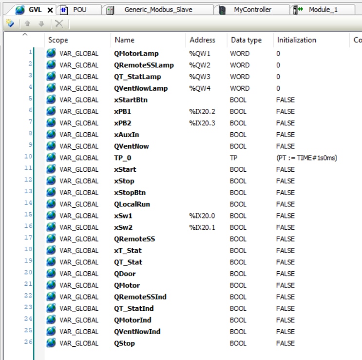
GVL stands for Global Variable List. Based on the recommendation of the tutorial videos, I made all of my variables global. This would also make them available when it came time to communicate with the HMI. A screenshot of the Global Variable List is included at the end of the next section, Assigning the Inputs and Outputs.
Assigning the Inputs and Outputs
Once the IO variables are defined in the variable list, they can be assigned to the appropriate device. The TM3DM8R IO Module was the easiest. Double click on it in the Device Tree changed the center window of Machine Expert to I/O Mapping for the module. At the BOOL level, clicking in the blank space just to the right of the blue boxes will allow you to add your variable assignments to that input/output. When you do, the program will strike through the address, indicating that it is no longer available for assignment.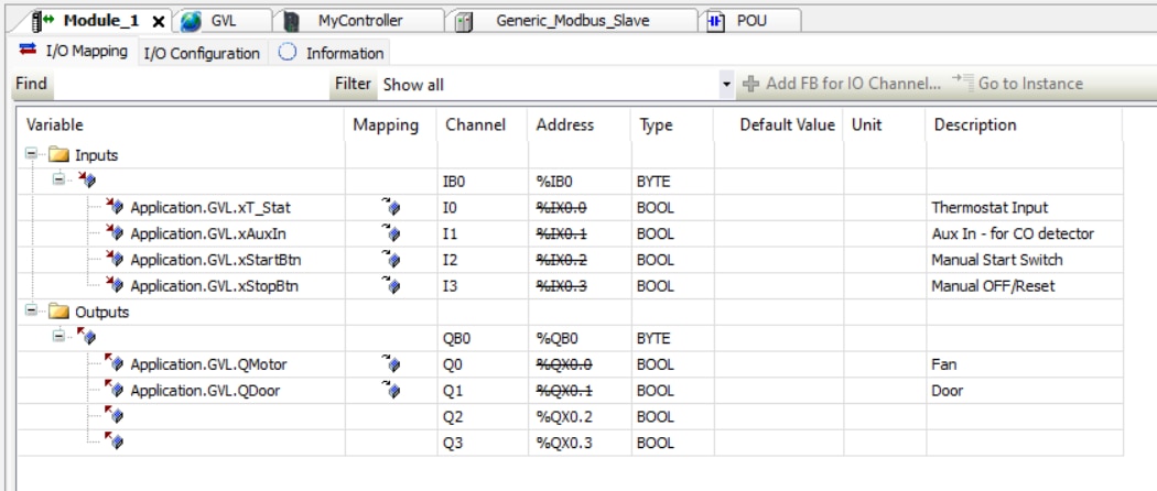
To assign IO in the ZBRN Harmony Hub, you first need to pair the transmitters and receiver. This is surprisingly easy. There are multiple videos that demonstrate pairing the transmitters to the Harmony Hub https://www.youtube.com/watch?v=Ri6ggVjfjh4
Surprisingly, I found no videos demonstrating how to pair the receiver module. It is similar, but you have to enable pairing in the receiver also before you start. The Harmony Hub user manual has the instructions.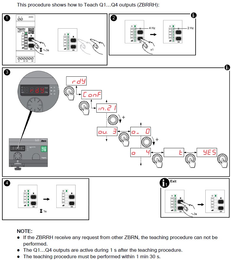
The instructions can be a bit unclear. I selected output channel 0 and it automatically assigned the four associated addresses of the receiver. Output channel 1 would be for an additional complete receiver.
You also need to setup the serial setting in the Harmony Hub. If you watched pairing a transmitter module, you already know how to perform this setup.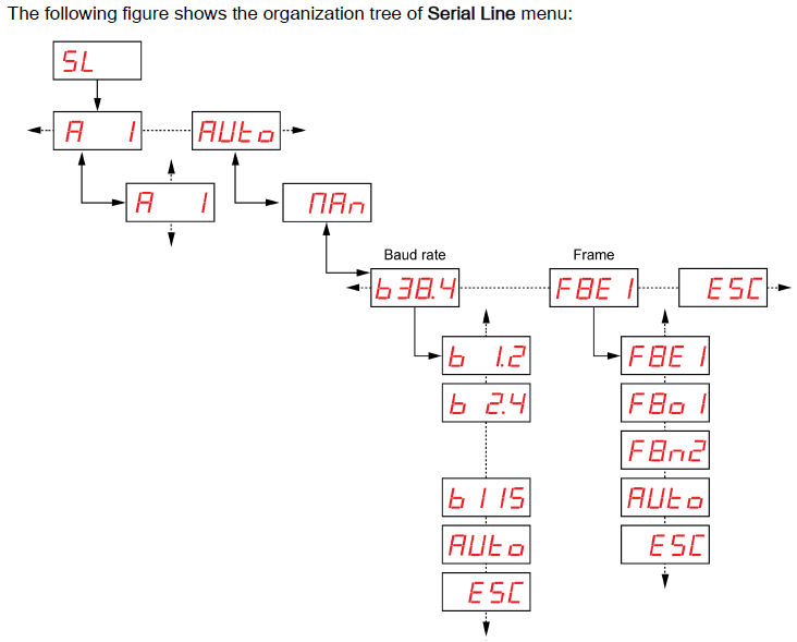
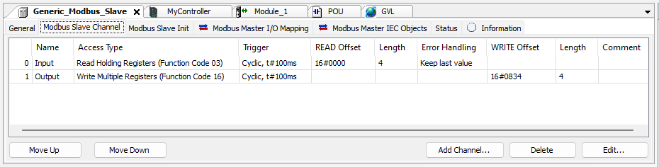
FINALLY we can start to assign the inputs and outputs to the Harmony Hub. Back in EcoStruxure Machine Expert, double click on the Generic_Modbus_Slave (or ZBRN2) line. The center window changes allowing us to configure this device. The first (General) tab allows us to assign the Modbus slave address. Make it agree with what you have in the Harmony Hub (typically 1). The next tab is Modbus Slave Channel. We need to add an input and an output channel.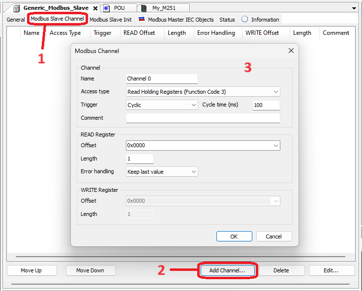
Once both channels are added, you should have the screen below.
From here, we can move to the Modbus Master I/O Mapping and see the addresses we need to assign our variables. These addresses get assigned in the Global Variable List.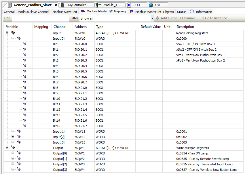
Running the Code
With all the variables defined and all the IO assigned, it's time to generate the code (think compile) and Login (think upload) it to to the PLC.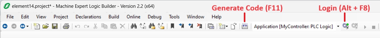
Because we are directly addressing physical outputs, we get this warning.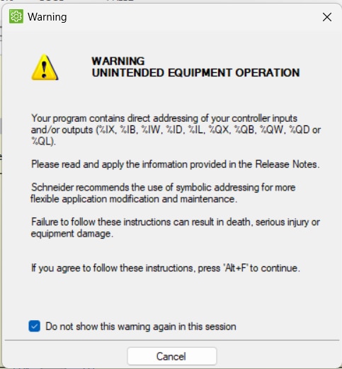
From here, we can select RUN and actually start the PLC to doing what we programmed it to do. After logging in, a small blue triangle pointing right appears. This is the RUN button. You get the typical "Are you sure?" pop-up. If you have changed values, you will be asked if you want to download the new program to the PLC. Select "Yes". Now we're up and running.
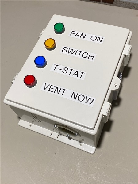
Seeing the Status
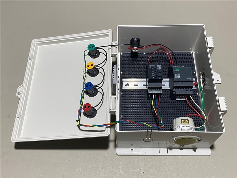
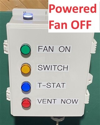
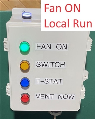
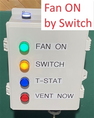
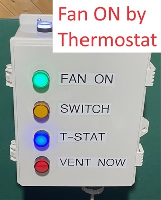
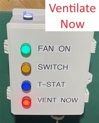
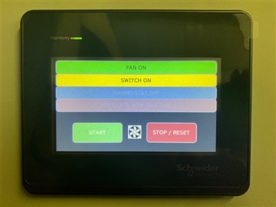
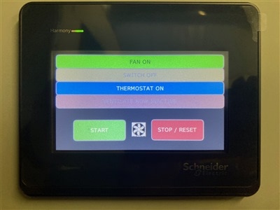
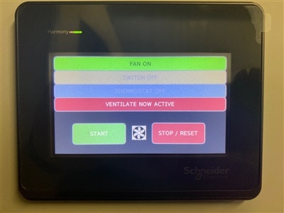
We have seen that the fan control location is less than convenient. Still, it would be nice to know not only that the fan is running, but also what is telling it to run. I chose to use the ZBRRH receiver in a remote annunciator panel. While the panel will probably not move once installed, it is built to be easily relocatable. "Switch" means wireless transmitter switches.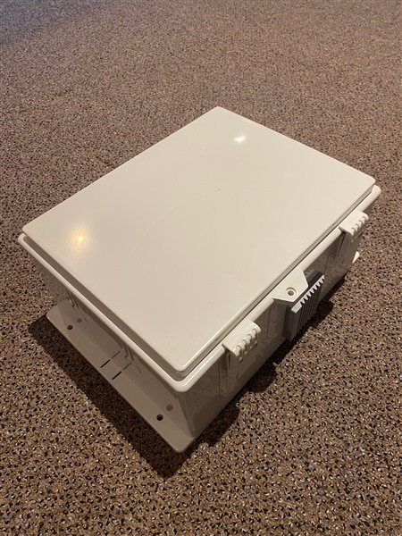
Remote Control
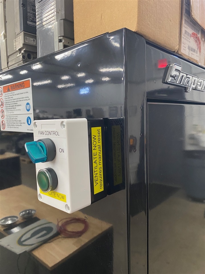
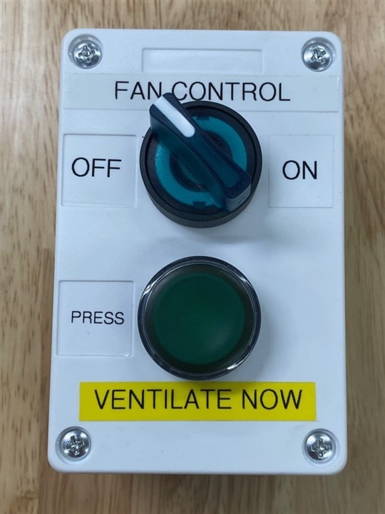
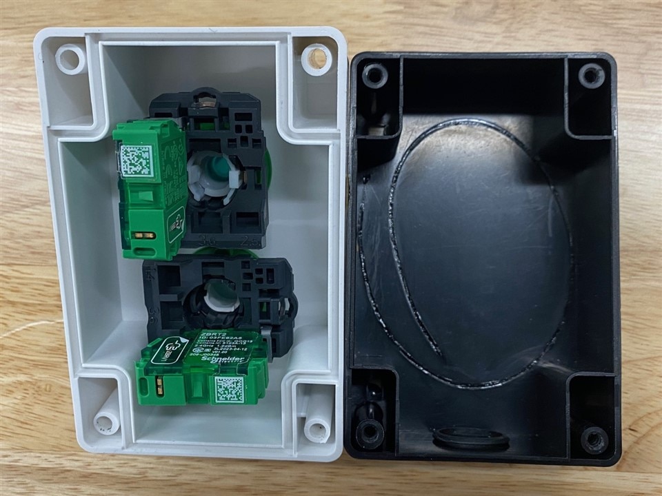
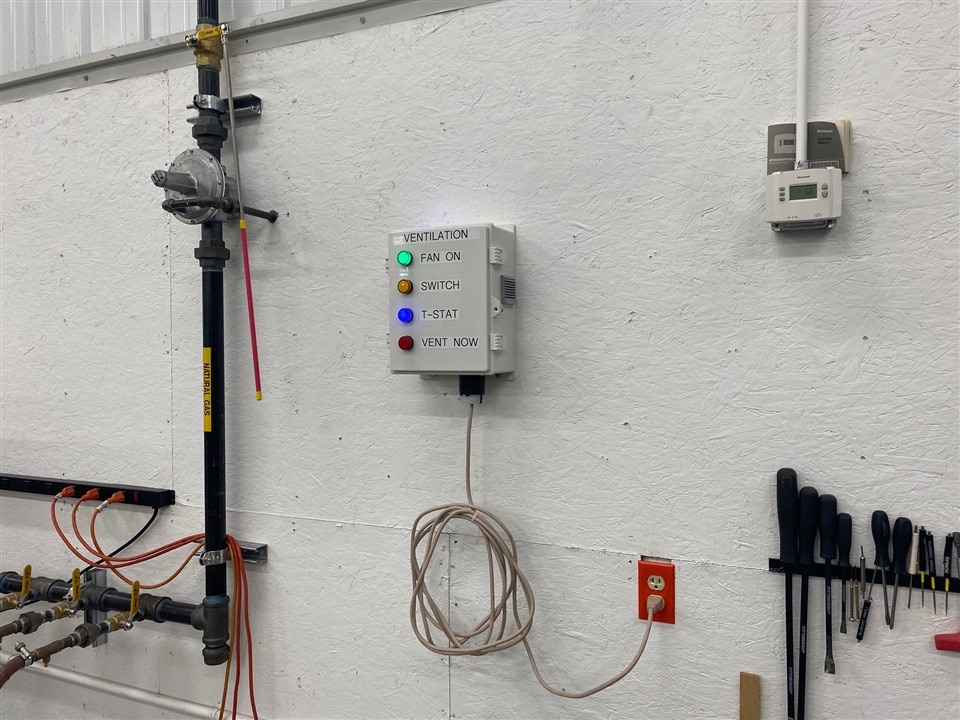
Remember back at the start of this blog that we wanted to control the fan from the door leading into the classroom? Here is the remote fan control with Ventilate Now button.
I also built a second remote fan controller with magnetic feet for use around the bay. Both ON/OFF switches work in parallel - so both have to be OFF for the fan to be OFF, but either Ventilate Now button will set that response in motion. Additionally, the remote with the magnetic feet has the ZBRV1 Visual Indicator installed. The visual indicator flashes rapidly for about a second when the switch is moved BUT the coolest part of it all is that it only flashes when it has received confirmation back from the Harmony Hub that the transmission was successful. It's a very handy tool and I did use it for testing the range of the wireless communication.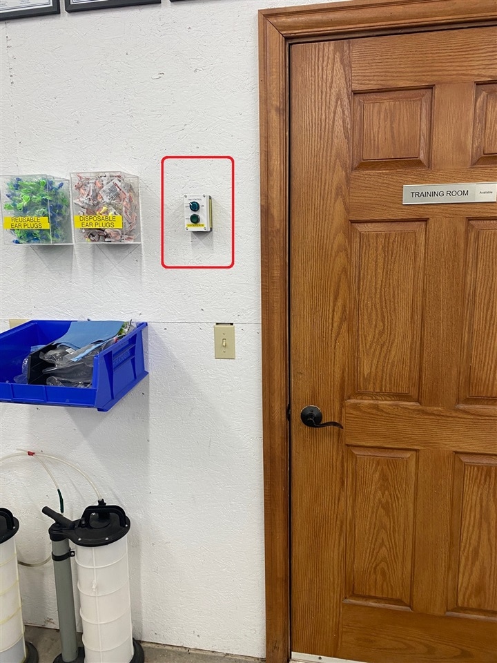
Integrating the HMI
While my project could run without an HMI, let's be honest - it just would not be cool without it. Touchscreen control and reporting are a foregone conclusion of today's technology.
Because HMI's are essentially computers unto themselves, they require different software to program and control. This software is Ecostruxure Operator Terminal Expert. It also has a trial mode that is functional for 42 days. Unfortunately, it does not allow uploads to a real HMI and is only supposed to run in emulation mode.
https://www.se.com/us/en/product-range/62621-ecostruxure-operator-terminal-expert/#software-and-firmware
I was able to use the software to design my user interface, but was never able to get the software to simulate my HMI. Thank you again the Schneider Electric and Randall Scasny of element14 for securing the Design Challenge participants a 3-month full license to the Operator Terminal Expert software. What I struggled with for weeks was moot in a few minutes with the full version. I only had the one challenge of the STOP button (detailed in the Writing the PLC Program segment).
Schneider Electric does have a series of video tutorials to help the newcomer. https://www.youtube.com/playlist?list=PLFqT6GhMpgpLuW145nJtN_snkrekeNpoG
The user interface on this software was frustratingly inconsistent. You either had to follow the tutorials or click around A LOT.
I used simple Lamps and Switches to create my interface. I did not need Scripts or anything fancy to create the level of control I wanted. Again, the full version of the software just worked. "Just worked" really means that I was able to set the network address of the HMI and upload that to the physical HMI. The HMI was now able to communicate with the PLC and exchange data. The only "magic" in the process is the Symbol Configuration found in the Tools Tree of EcoStruxure Machine Expert.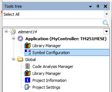
When selected, this section allows you to choose which variables will be shared with other device - specifically the HMI in my case.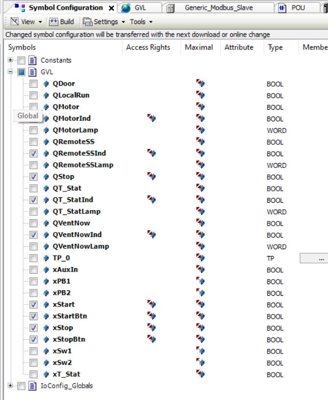
You will probably need to click on "Build" above the top of the list from time to time. When generating code (F11), this also creates an XML file that can be uploaded into Operator Terminal Expert to define the shared variables. The generated file is found in the same default folder as any saved *.project files you save. There is only one XML file.
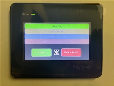
Yes. I am saving the cool HMI screens for the finale.
Range Testing
With the system functional, it was time to test it in an industrial environment. Both the transmitters and receives claim a 100 meter range in free space to a Harmony Hub with no external antenna. This decreases to 25 meters if one of the devices is in a metal enclosure. I am using plastic enclosures on both sides, so I was unsure about the performance. Remember, my Training Bay has half metal clad walls.
I placed the Harmony Hub in its enclosure on one side of our main building (because it is larger) and the ZBRRH annunciator and wireless control station as far as I could and still have direct line-of-sight; 125 feet. I flipped the switch. It works.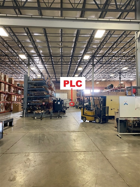
I move the annunciator and control station as far back as I can. Now the path is obstructed with multiple large generators. It still works. 155 feet.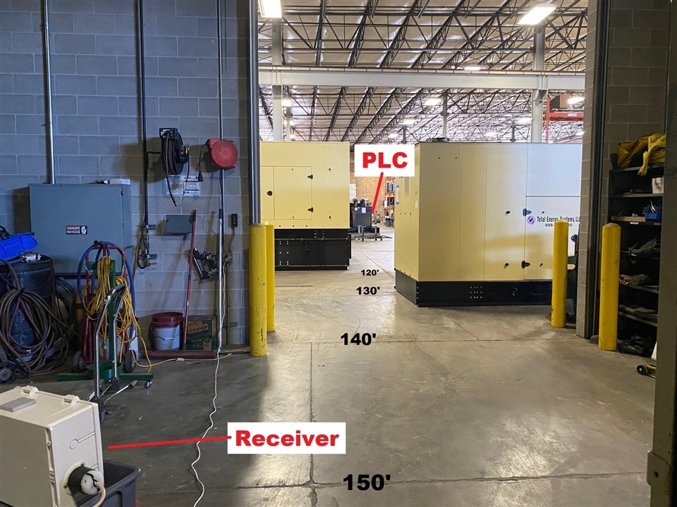
I had to move 25 feet into the cinder block room for the system to exhibit intermittent communication. Impressive.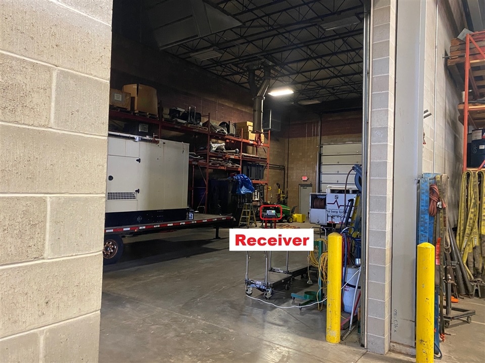
Given the performance of the Harmony Hub ecosystem without the external antenna, additional testing with the antenna or with the repeater antenna is essentially moot. While I will install the repeater antenna anyway, I am most impressed with the performance of this system. It far exceeded my expectations and it will work well in my application - regardless of how much or what type of Executive Storage is placed in the Training Bay.
Project Completion
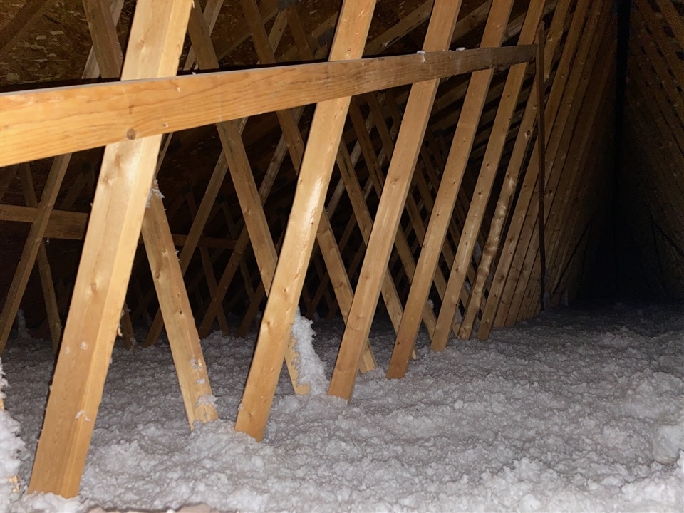
With all the equipment provided for the Experimenting with Industrial Automation Design Challenge configured and working, there were still a few things left to do to finish the project. One was run the control wire from the commercial garage door to the fan control. Of course the existing pushbutton station was even further away from the fan control than the motor assembly so I started there. Either choice would have had me crawling in the attic anyway. The ceiling is just shy of 15 feet up. The access hatch is a little obstructed by the radiant heater and, I don't think any picture can capture how miserable it was to string 100 feet of HVAC control wire through the jungle gym of the rafters.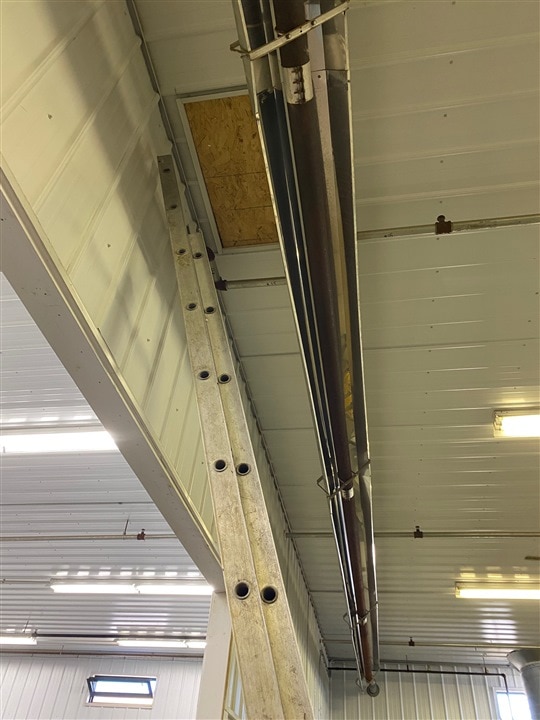
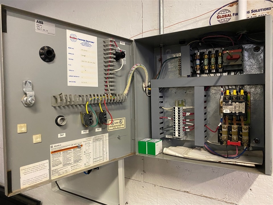
Mounting the new control system on the wall was much more rewarding. I was a little anxious about unwiring the existing control. We're fully committed now!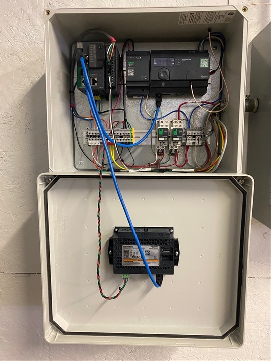
Of course, I tested each function on both remote fan controllers and the START/STOP function of both the HMI buttons and the physical buttons.
And... the door. The clip runs about 8 seconds and you can hear when the fan kicks on behind me in the video.
While the fan control location is still buried...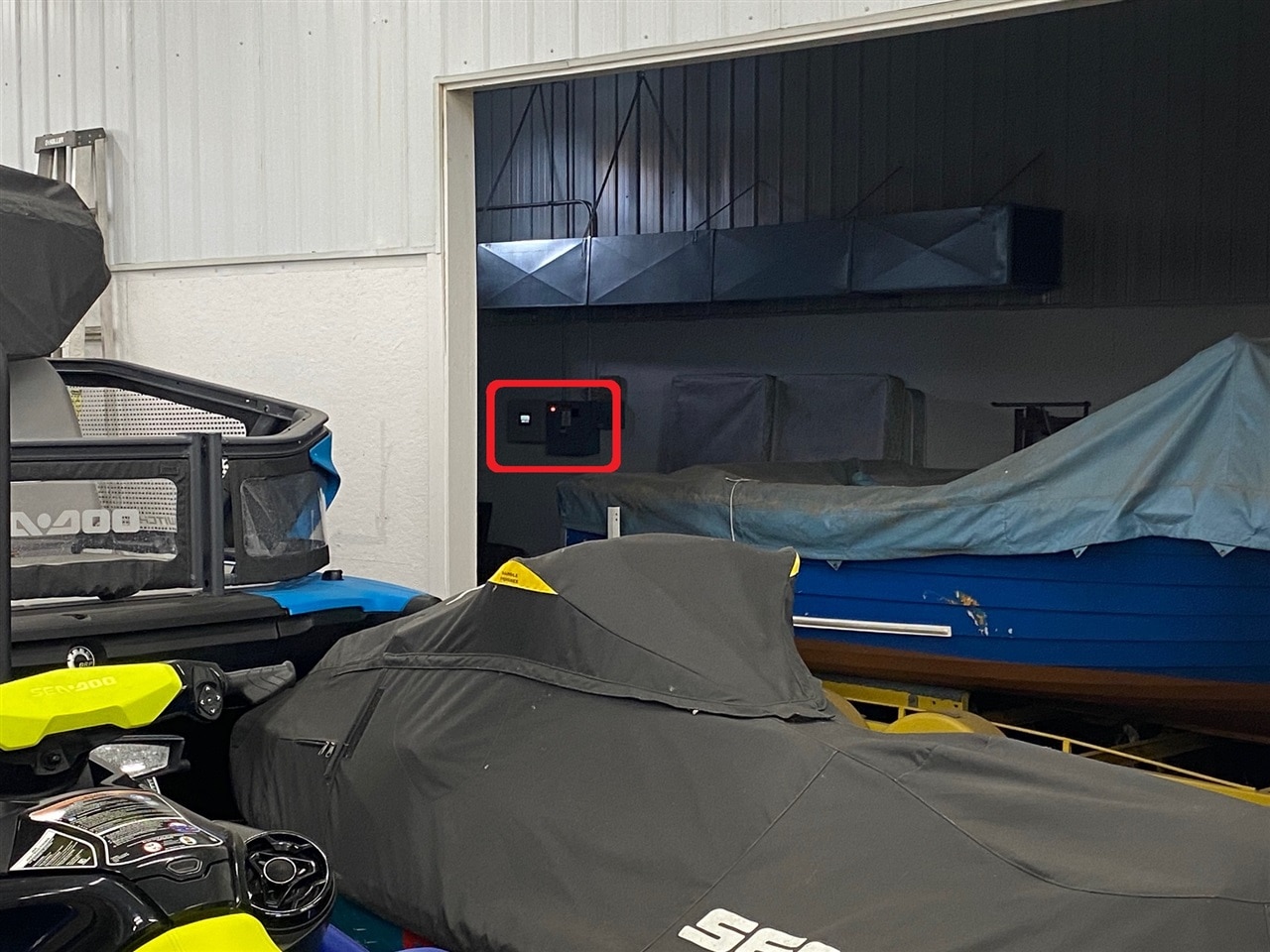
... it only matters now if you push the Ventilate Now button.
Even though it is not required, I did find a home for the ZBRA1 Relay Antenna. With that, I should be able to put the remote fan controllers inside the generators and still have them work.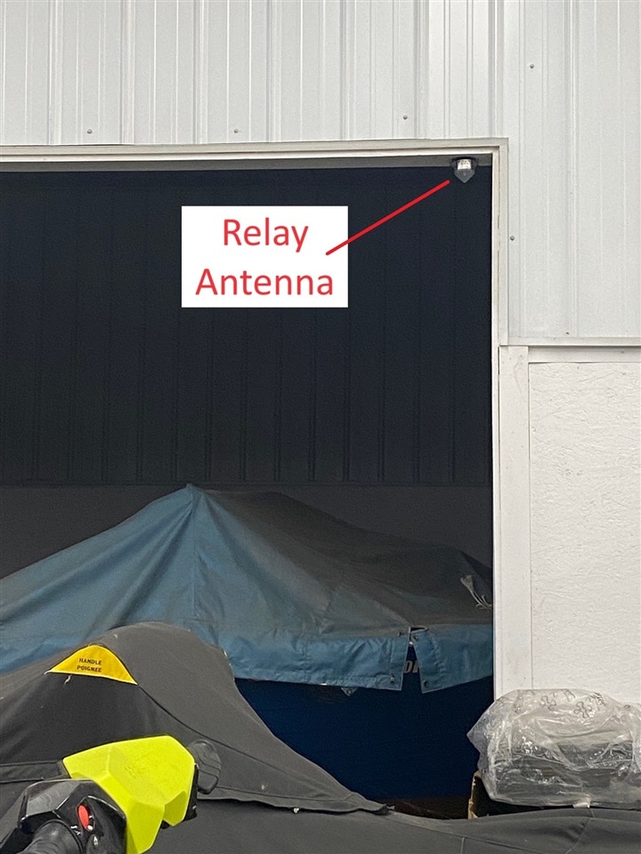
Conclusion
Again, thank you Schneider Electric and element14 for the opportunity to work on a "bucket list" project. There were points where I worried (a lot) if I would be able to complete the project. Once those challenges were resolved... the project became fun again. I can absolutely see where these devices would be extremely beneficial in an industrial environment that had to change its layout or retool from time to time. Climbing through the attic of my building to run the door control wiring accentuated how nice wireless control can be. It was even more exciting when I did the communications testing and the range wound up far exceeding my expectations. The time savings in setting up control and monitoring systems is almost mind boggling. While the devices were cool at the start of the project, they are even more impressive now that they are in place and working.
For the person reading this Design Challenge asking the question, "Is it worth the expense?", I say "yes". Running conduit and wire is expensive as well. The difference is that the Harmony ecosystem can be reconfigured and reused. The wire and conduit... not so much.
Stretch Goal
My initial stretch goal was to integrate an automatic "Ventilate Now" response from a carbon monoxide detector. The functionality has already been added to the PLC. The add-on module to the carbon monoxide detector exists and is fairly reasonable in price. BUT... I have had second thoughts from a security perspective. I am not comfortable with opening the Training Bay garage door when the building is unoccupied - which is what the feature could do. Yes, it would set off the building security alarm, but there is no need to ventilate an unoccupied building. For the "first in" person, they would hear the carbon monoxide detectors once they unlocked the door to enter and know not to proceed. So... the capability is there. I do not plan to use it at this time.
Other Blogs
Blog 1 - The Automate Ventilate Plan The project plan
Blog 2 - A Box Full of Industrial Automation What's in the box / unboxing
Blog 3 - Beginner Industrial Automation Path Tidbits for someone just starting out
Blog 4 - Setting Up IO on M251 PLC Through ZBRN2 Harmony Hub The solution to my biggest hurdle
Blog 5 - Range Test of Harmony Hub Ecosystem - Wireless range testing
.
Top Comments