I would like to thank Element14 community and Schneider Electric for choosing me as official challenger for their Experimenting with Industrial Automation contest. For this design challenge, my project was to create a project for overhead tank liquid level monitoring for smart home/industry. This means the project can be useful to monitor water level in the tank inside house but at the same time it can be used to monitor other liquids and chemicals in the industry considering and using required safety considerations.
This is a final project blog for Overhead tank monitoring for smart home/Industry.
-
Overhead tank monitoring for smart home/industry : BLOG 1
-
Overhead tank monitoring for smart home/industry : BLOG 2
-
Overhead tank monitoring for smart home/industry : BLOG 3
-
Overhead tank monitoring for smart home/industry : BLOG 4
Table of Contents
- Overhead tank monitoring for smart home/industry : BLOG 1
- Overhead tank monitoring for smart home/industry : BLOG 2
- Overhead tank monitoring for smart home/industry : BLOG 3
- Overhead tank monitoring for smart home/industry : BLOG 4
- Introduction to the project
- Working with PLC
- Working with Harmony Hub(ZBRN2), wireless receiver(ZBRRH) and antenna(ZBRA1) and wireless wireless switch(ZBRT2)
- Working with HMI ST6200
- Final project demo
- Conclusion & Final remarks
- References and documents
Introduction to the project
Water is an important resource. We all use water daily and it is not possible to imagine a life without water on earth. In fact, earth is only know planet where life exists and that is due to availability of water. We use water for drinking and other day to day activities. But despite having so much use water is wasted every day. Due to lack of management and awareness we are loosing so many litres of water that could be used for other purpose. Not only remote places or deserted areas are suffering from lack of water but in recent time places that have plenty of rainfall and reservoirs are also suffering not having enough water. So many people have heard about Johannesburg that had plenty of water shortage. One recent example is the city of Bangalore where there is shortage of water. These are just known names but I am sure there will be many other places that are going through the hard times due to lack of basic needs. So for this challenge I came up with this idea of automatic tank monitoring and filling in house or industrial use cases.
Many people ask me how this project can be useful in house compared to cost that it would have? My answer to them is simple. It might be costlier in the beginning compared to other alternatives but there are a few points to consider. I will list them as following.
- Smart homes are going to be no less than a factory, PLC can take over many tasks that could be done individually with tiny MCU devices so the overall cost and complexity will decrease. The maintenance cost will also decrease as a result of reduced complexity.
- Scaling of the project is much much easier compared to other as these are wireless devices and Harmony Hub can tackle so many devices at a time using wireless technology. Many homes and apartments have more than two tanks with some having even 5 to 6 tanks.
- Chances of failure of the system is less and debugging is easier using PLC.
- Centralised monitoring and control is way more easier than conventional technologies.
- Last but not the least, it is one time and hassle free installation and investment.
So in my first blog, I had mentioned my plans and the overall system design I wanted to achieve. Thankfully with Schneider Electric devices so many things went well and as planned. Specially, as I come from wireless communication background, I enjoyed working on Harmony hub(ZBRN2) and associating input and output channels to the device.
Working with PLC
Working with Harmony Hub(ZBRN2), wireless receiver(ZBRRH) and antenna(ZBRA1) and wireless wireless switch(ZBRT2)
**Note: I will use ZBR name during this project and not the full name.
Working with Harmony Hub(ZBRN2) and device association was one of the interesting work during this design challenge. ZBRN2 has possibility to connect to serial Modbus ASCII or RTU device using one of the two RJ-45 port pins. On the PLC side also there is one serial port that can be used for this purpose. After connecting the devices through RJ-45 cable one can add Device tree node for the ZBRN2 device(I have explained this in previous blogs as well).
When I added ZBRN2 the input registers and address were already specified so I did not need to do anything to see the pushbutton status. As soon as I went online with the PLC, I was able to see that the respective bit Boolean value changes on the press of a button. From there I got an idea to use this value and use the ZBRT2 with switch rather than a push button for my project so that I can create manual/auto and ON/OFF switch states easily.
For setting up the push buttons or ON/OFF switch it was required to assemble the wireless and battery less transmitter ZBRT2 with the mechanical switch. It was somewhat tricky in the beginning how to do that but the final results of this innovative assembly is in the bellow picture. Finally, an indicator module ZBRV1 can be attached to transmitter and the switch that blinks LED when we change the switch positions. (Finally, switches are ready to run the motor remotely
)

Now it is time to look at ZBRRH wireless receiver module. Upto 60 ZBRRH wireless receivers can be connected to ZBRN2 hub. It has four outputs Q1, Q2, Q3 and Q4. These outputs can be in one of the following states.
- 0x00 --> Output off
- 0x5A --> Output blink
- 0xFF --> Output on
The receiver ZBRRH can be associated to the output channel on ZBRN2 by using jog dial on the ZBRN2. I have connected Q1 output of the receiver to the relay module hence it can be controlled from the PLC. For that I tried simple ST(Structured Text) program.
Working with HMI ST6200
To work with the HMI ST6200 we need EcoStructure operator terminal. The software needs licensee in order to upload the code to the device. It is I would like to thank again to rscasny , Element14 and Schneider electric for providing license to the official challengers.
Mainly I wanted to use the HMI ST6200 to have real time display of tank water level by establishing communication between the PLC and HMI module. There are some different methods to do this. As I was relatively new to how to do this I took some help from online videos and documentation to make it work. So far I do not have success to establish the communication between devices. BTW there are two possible methods using either Ethernet port between these devices or using serial line. As I have Harmony Hub(ZBRN2) connected to the serial port, I was left with Ethernet option (I did not even try the serial option).
For communication using Ethernet, there are also some options. First one is using Nodename(of the PLC in machine expert) and another is using IP address. Both these methods are explained in following video. I tried them both. Unfortunately, I was not able to have communication between these devices yet. I will update this section once I have done it.
Link-1 https://www.youtube.com/watch?v=ZGvNAPbo-Hs&t=802s
Link-2 https://www.youtube.com/watch?v=DOiaDWveGsY&t=1228s
Final project demo
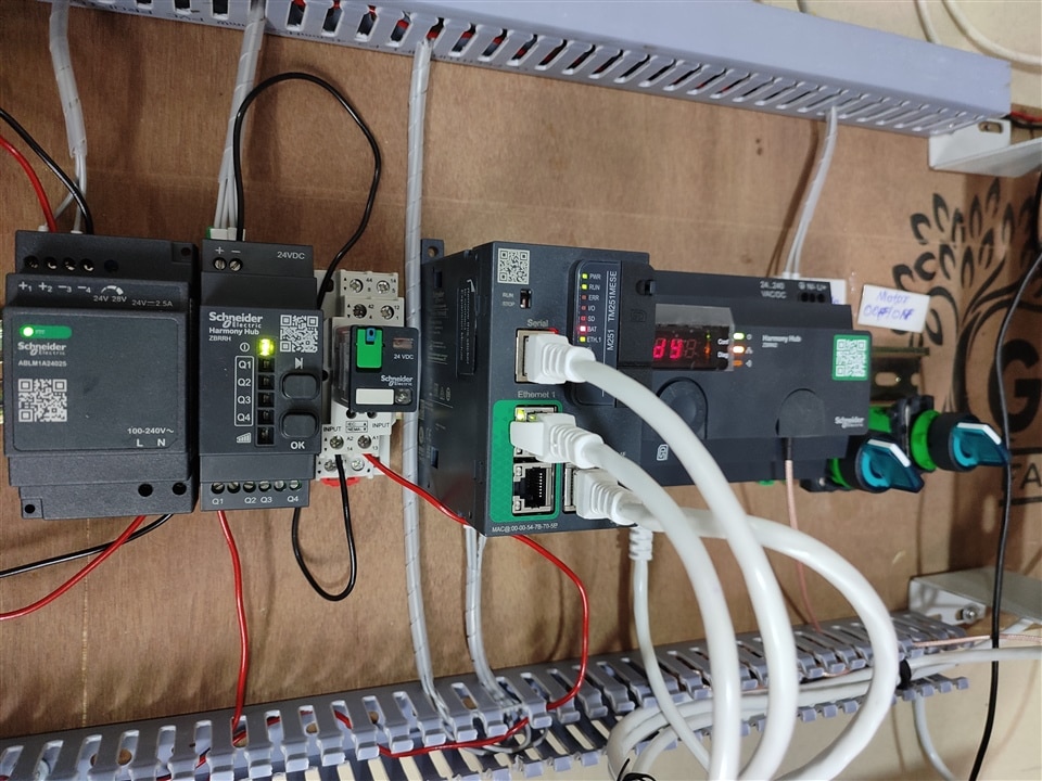
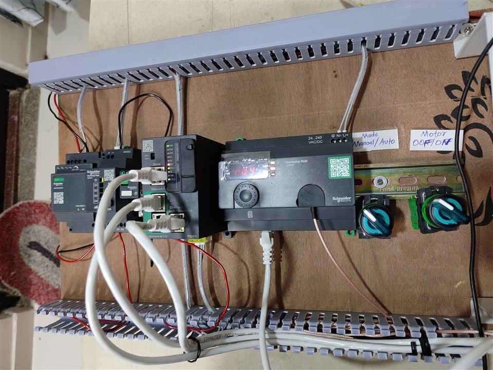
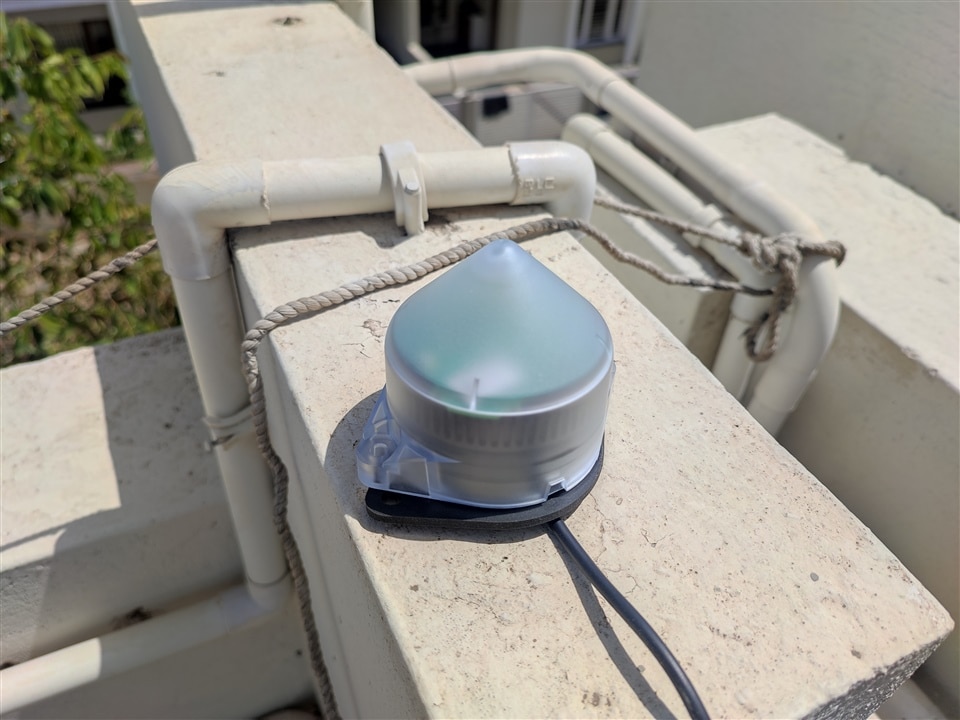
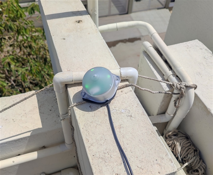
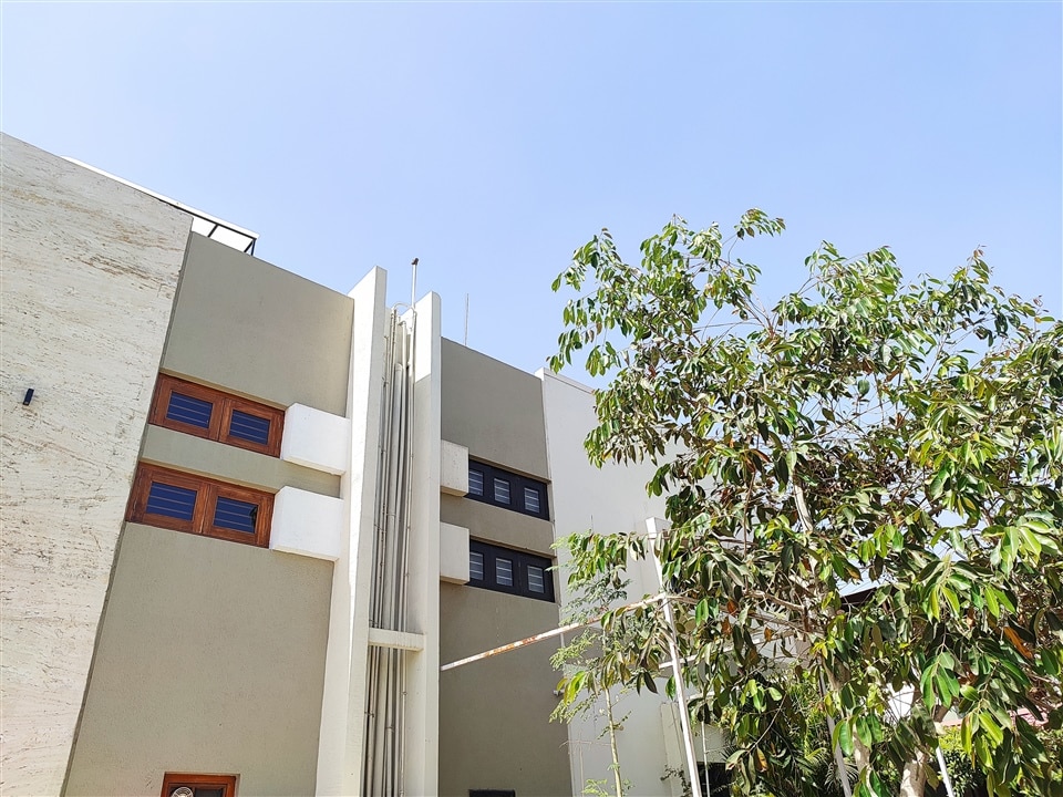
The final project uses devices listed in the following picture plus ZBRA1 antenna. The antenna is mounted on the top flor of the home so that radio signal can be received from all parts of the house and outside of the house. I have tested the range of antenna. It has quite some range in open field(at least up to 100 meters I have tested).
| {gallery}My Gallery Title |
|---|
|
Final Project setup demo |
|
Final project setup demo |
| {gallery}My Gallery Title |
|---|
|
Antenna placement |
|
Antenna on tarace |
|
House outside view and antenna placement |
Structure text code and variables
For this project I have used ST(Structured Text) coding language. It is a kind of programming language like ladder logic or functional diagram. As I am more used to coding for embedded systems, I used C/C++ and other text kind of language more often than a graphical language. Also, it has some advantages such as low memory requirements for resource constrained PLCs.
So here in these two code snipet is the code for PLC. The first one is the declaration of the variables that are used in the program and second one is the actual code.
The code is using simulated sensor values as I am yet to integrate real sensor. The integer value for sensor ranges from 0 cm to 200 cm. I increase this value every two seconds to simulate the sensor value.
There are two modes in this project. AUTO and MANUAL. There are two switches to control these modes. If MANUAL mode is active then sensor values of tank water level is ignored and motor to fill the tank can be controlled manually using the switch wirelessly.
If AUTO mode is active then If the water level in the tank is too less(below or around 20 cm) then motor will start. If the water level crosses 180 cm mark then motor will stop automatically.
The following code demonstrates the functionality that I have mentioned.
Variable declaration
PROGRAM SR_Main
VAR
TANK_WATER_LEVEL: INT:= 25;
PUSHBUTTON_1: BOOL; //MANUAL/AUTO mode select switch
PUSHBUTTON_2: BOOL; //OFF/ON Switch
MOTORSTATUS: BOOL;
MOTORSTATUS_LAST: BOOL;
Q4_OUTPUY: INT;
INPUT: INT;
Delay : TON;
Count : INT := 0;
END_VAR
The ST code
PUSHBUTTON_1:= %IX40.4;
PUSHBUTTON_2:= %IX40.2;IF TANK_WATER_LEVEL >= 200 THEN
TANK_WATER_LEVEL:=0;
END_IF
//Delay of 2 seconds
Delay(IN := TRUE, PT:=T#2S);
IF NOT(Delay.Q) THEN
RETURN;
END_IF
Delay(IN:=FALSE);
TANK_WATER_LEVEL := TANK_WATER_LEVEL + 1;//if Switch_1 is in manual and Switch_2 is in OFF postion//
IF PUSHBUTTON_1 = FALSE AND PUSHBUTTON_2 = FALSE THEN
%QW20 := 0;
MOTORSTATUS := FALSE;
MOTORSTATUS_LAST := MOTORSTATUS;
//if Switch_1 is in manual and Switch_2 is in ON position then motor=ON//
ELSIF PUSHBUTTON_1 = FALSE AND PUSHBUTTON_2 = TRUE THEN
%QW20 := 65535;
MOTORSTATUS := PUSHBUTTON_2;
MOTORSTATUS_LAST := MOTORSTATUS;
//if Switch_1 is in auto mode and water level in tank<=20 cm then motor==ON
//regardless of status of Switch_2(ON/OFF)//
ELSIF PUSHBUTTON_1 = TRUE AND TANK_WATER_LEVEL<=20 THEN
%QW20 := 65535;
MOTORSTATUS := TRUE;
MOTORSTATUS_LAST := MOTORSTATUS;
//if Switch_1 is in auto mode and water level in tank>=180cm then motor==OFF
//regardless of status of Switch_2(ON/OFF)//
ELSIF PUSHBUTTON_1 = TRUE AND TANK_WATER_LEVEL>=180 THEN
%QW20 := 0;
MOTORSTATUS := FALSE;
MOTORSTATUS_LAST := MOTORSTATUS;
END_IF
The following is a video of EcoStructure Machine expert that is running the PLC application. We need to go online with PLC and run the application in order to see all the variables and status of the motor. It show different variables such as TANK_WATER_LEVEL, MOTORSTATUS, PUSHBUTTON_1 etc.
As I have explained earlier if the device is running in auto mode then motor will start as soon as water level inside the tank is below 20cms and it will stop if the water level is above 200 cms. This is for the tank that I have inside my home with 200cm height. In manual mode regardless of water level the motor will just follow the switch status. Curretly, I do not have real motor connected to the PLC but I observe the relay status(tick sound)..
\
Conclusion & Final remarks
For me it was honor to take part in this design challenge from Schneider and element14. This was the first time I tried something that is meant to be used in Automation industry. The devices as I have worked with are quite compact and modular. The advantage is that one can get started easily and the software makes the things easy for user to configure different variable values and settings. This advantage is not there in embedded devices such as MCU based products. The difficult part for this design challenge for me was to communicate between the PLC and HMI module. I am sure I will be able to solve this issue. The devices have far more capabilities than I have used in this challenge project.
Fortunately, all the devices that I have received for free for this project are of use in my project. In fact, I have make use of each one of them. From the blogs of other official challengers I realized they have used I/O module to control the outputs from the PLC. Fortunately, it was not required for my use case and I was quite relieved from the hassle of ordering stuffs online and waiting long for them to arrive.
Finally, many people around me and also from element14 community asked about the cost of the project if they have to design such setup. I have mentioned why Schneider electric devices are worth to do this tasks in Blog-4. One of the main reason is that with these devices scaling of project becomes lot more easier and smarter than other electronics devices. With PLC and Harmony Hub based wireless ecosystem one can control as many devices as they want to remotely. This flexibility is rare with other tiny electronics.
I am going to continue to work on this project. Due to limited time for this design challenge and busy schedule for me from January end it was not possible for me to concentrate enough on this project. There is way more that one can do in this project and I am going to install the system in my home.
References and documents
- Harmony Hub(ZBRN2) user guide
- Machine Expert Programing guide
- PLC M251 user guide
- ZBRA1 Antenna guide


Top Comments