


Summary
After 5 weeks doing experiments and learning about analog electronics and magnetic components it is time to try to design and build something practical, my DIY Inductive Sensor.
Thanks to element14 and Bourns during these weeks I have learned about coils, inductors, chokes, transformers and ferrite cores and their main uses: Choking, blocking, attenuating, filtering and smoothing high frequency noise, storing and transferring energy in power converters (dc-dc or ac-dc ), making tuned oscillators or LC tank circuits and impedance matching. I have practiced with Colpitts oscillators, with LC tanks, with transformers, with common-mode chokes, with inverting amplifiers with transistors, with amplifiers with Op Amps, with voltage followers, with peak detectors, with bypass capacitors and decoupling capacitors, with rectifiers, voltage dividers and power supplies. I have learned the basics of handling the Analog Discovery 2 USB Oscilloscope Analog Discovery 2 USB Oscilloscope, the signal generator, the programmable power supplies, the impedance and spectrum analyzer. I didn't think I was going to get that far.
Disclaimer
This is the design of a rookie, sure I have made more than one mistake or things could have been simplified but for me the design works and the learning experience has been excellent, better than I expected when starting this challenge.
If you are going to try to replicate this project, keep in mind the limitations of the microcontroller that you are going to use with the sensor. Check well the voltages and currents allowed. It may be necessary to limit them.
Inductive Sensor Blog
Within the Experimenting with Magnetic Components Challenge I am conducting experiments to develop a smart coin discriminator using inductive sensitivity. In this blog I describe the construction of the final device, the inductive sensor, that will allow me to capture the data for classifying the coins with a microcontroller.
At first, the idea was to capture the reference signal and the signal modified by the presence of the coins through the ADCs of the Arduino BLE. The Arduino BLE features a nRF52840 processor from Nordic Semiconductors, a 32-bit ARM Cortex
  -M4 CPU running at 64 MHz. The Arduino BLEArduino BLE has 8 ADCS with12 bit resolution and can sample, 200 k-samples per second.
During the experiments I tried to achieve a configuration of the oscillator and the LC tank that allowed to work at a frequency low enough to be able to sample the signal with 200 k-samples of the ADCs of the nRF52840. I could not get below 15 kHz which did not allow to have a good sampling of the signal for the purpose of being able to discriminate coins based on the phase shift and the impedance change.
Therefore in the final device I resort to using two digital inputs to create a kind of phase meter and two analog inputs to detect the impedance change when the coins are brought closer to the LC Tank.
Inductive Sensor Overview
The sensor can detect subtle changes in the varying magnetic field through the interaction of a metallic object such as a coin. The sensor has a parallel LC (inductor + capacitor) resonant circuit that generates a variable magnetic field when an alternating current flows through it. If a metallic object is placed in the vicinity of the alternating magnetic field produced by the inductor, eddy currents are induced in the metallic object on the metallic surface of the object. These eddy currents produce their own magnetic field that opposes the one created by the inductor that reduces the effective inductance of the coil.

The sensor has four outputs, two analog outputs, and two digital outputs.
- The analog outputs represent the positive half wave signal of the voltage and "current" in the LC tank ("current" signal is voltage across a shunt resistor)
- The digital outputs are pulses that detect the crossing of the voltage and "current" signal through a certain voltage level set by a resistor.
Outputs:
- A1 Pre-scaled rectified analog voltage signal
- A2 Pre-scaled rectified analog "current" signal
- D1 digital voltage crossover detector pulse for voltage signal
- D2 digital voltage crossover detector pulse for "current" signal
Using the outputs with the microcontrollers analog and Digital ports:
- Measuring Impedance Change (ADC): Measuring the difference of the peaks of the analog signals we have the relative change in the impedance of the LC Tank.
- Measuring Phase Shift Change (Digital): The time elapsed between the two bisectors of the pulse lengths gives us the phase difference in seconds.

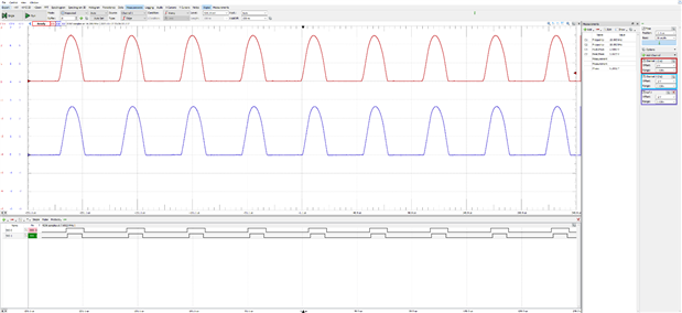
The figure shows the four sensor outputs. Above the two analog outputs for the peak detector and below the two pulses that allow measuring the phase shift between voltage and current.
Block Diagram
Simplified block diagram of the system for classifying coins. The first block is half done, I did not have the proper inductors and only the bypass capacitors have been included.

- The oscillator generates a sine wave tuned to the same resonant frequency of the LC tank. The oscillator is a Colpitts oscillator with op amp.
- The oscillator circuit is isolated from the LC tank driver circuit by a 1: 1 ratio transformer.
- The LC tank is isolated from the oscillator circuit and the signal is filtered by a line filter.
- The LC tank generates a variable magnetic field while waiting for a coin or other metallic object to approach. Both the input signal to the tank and the output are scaled by a voltage divider and are buffered and clipped to match the inputs of the microcontroller.
- The two signals are divided into two others.
- Two are used to measure the phase shift of both signals by means of two optocouplers that generate a pulse when reaching a certain voltage level;
- and the other two are rectified and used to calculate the amplitude of the signal by means of a peak detector in the microcontroller.
- Finally, the two values obtained feed the k-NN classifier to obtain the class to which the target coin belongs.
Magnetic Components
The sensor uses several magnetic components from the Magnetic Components Kit See Kit
The Coopitts Oscillator uses this RLB1112V4-102JRLB1112V4-102J 1mH Radial Inductor
| 400 Volt Radial Inductor |

The Isolator uses the BOURNS HCTSM80102AAL-E1HCTSM80102AAL-E1 as a 1:1 transformer
| Pulse, Transformer, 250µH |

Line filter to reduce EMI emissions uses the BOURNS SRF9045A-701YSRF9045A-701Y
| Common Mode Choke, 7.5 µH |


The LC Tank sensor uses the BOURNS RLB0914-102KLRLB0914-102KL
| Inductor, Radial Leaded, 1 mH |

Schematics

Soldering Protoboard
During the experiments I used solderless breadboards with mixed results. I had quite a few stability and noise issues with the oscillator so for the final prototype I decided to use a soldered protoboard.

Functional blocks
Oscillator Block
For the oscillator in the final design I use the op27 operational amplifier which is the one that has given me the best results in the experiments.
https://www.analog.com/media/en/technical-documentation/data-sheets/OP27.pdf
The OP27 is a low noise, precision operational amplifier.

Isolator, Line Filter & LC Tank blocks
The transformer acts as a galvanic isolator and the common mode choke is used to reduce EMI emissions.
Schematics:

R14 is a shunt resistor that allows us to obtain a coherent waveform with the one that is following the current in time.
LC Tank, twisted pair cabling and ferrite core

Buffered output LM324N stage and Signals Splitter
The sensor divides the two signals to be examined, voltage and "current" in two by means of two Y-splitters and the help of 4 voltage followers.
Use the four Op-Amp modules of an LM324-N Quad to build 4 buffers or voltage followers.
LM324-N Quad, 32-V, 1-MHz op amp
https://www.ti.com/product/LM324-N


Schematics: 2x Y-splitters and 4 x Voltage Followers


Digital Outputs: Phase shift meter with two 817 optocouplers
By means of the optocoupler the circuit generates pulses of detection of passage by a voltage reference. Being a periodic signal, this will allow us to calculate the frequency of the signal and by comparing the bias of the pulses of two signals to calculate the phase shift between the two. In our case, the phase difference between voltage and current through the LC tank is of interest.
The 817 contains a light-emitting diode optically coupled to a phototransistor.

HCPL-817: Phototransistor Optocoupler High-Density Mounting Type Data Sheet (broadcom.com)
Schematics:

Tune R6 and R7 for proper pulse lengths.

Analog Outputs. Rectifier stage

First attempts with the rectifier using 1n4005 diodes. Sensor response to different coins.
Final design with the 1N914 Small Signal Diode

Output signals. Analog and Digital
Analog rectifier signals with the 1N914 Diode. In the figure both digital and analog outputs.
Next steps
Things to do:
- Build a holder for the sensor and coins
- Prepare the sketch for data collection on the Arduino.
- Collect data to train the classifier.
- Make a cool blog and video to showcase the coin classifier to the element14 community.
Conclusion
It has been a very special design challenge for me totally out of my comfort zone. I want to thank Randall Scasny for encouraging me to participate and select my application even though I was a newbie to analog electronics. I hope I have not been too wrong in the explanations of my blogs and thanks to those who have visited the blogs, I am a bit overwhelmed by the number of visits they are having.
Top Comments