element14 Community
element14 Community
    Register Log In
  • Site
  • Search
  • Log In Register
  • Community Hub
    Community Hub
    • What's New on element14
    • Feedback and Support
    • Benefits of Membership
    • Personal Blogs
    • Members Area
    • Achievement Levels
  • Learn
    Learn
    • Ask an Expert
    • eBooks
    • element14 presents
    • Learning Center
    • Tech Spotlight
    • STEM Academy
    • Webinars, Training and Events
    • Learning Groups
  • Technologies
    Technologies
    • 3D Printing
    • FPGA
    • Industrial Automation
    • Internet of Things
    • Power & Energy
    • Sensors
    • Technology Groups
  • Challenges & Projects
    Challenges & Projects
    • Design Challenges
    • element14 presents Projects
    • Project14
    • Arduino Projects
    • Raspberry Pi Projects
    • Project Groups
  • Products
    Products
    • Arduino
    • Avnet & Tria Boards Community
    • Dev Tools
    • Manufacturers
    • Multicomp Pro
    • Product Groups
    • Raspberry Pi
    • RoadTests & Reviews
  • About Us
    About the element14 Community
  • Store
    Store
    • Visit Your Store
    • Choose another store...
      • Europe
      •  Austria (German)
      •  Belgium (Dutch, French)
      •  Bulgaria (Bulgarian)
      •  Czech Republic (Czech)
      •  Denmark (Danish)
      •  Estonia (Estonian)
      •  Finland (Finnish)
      •  France (French)
      •  Germany (German)
      •  Hungary (Hungarian)
      •  Ireland
      •  Israel
      •  Italy (Italian)
      •  Latvia (Latvian)
      •  
      •  Lithuania (Lithuanian)
      •  Netherlands (Dutch)
      •  Norway (Norwegian)
      •  Poland (Polish)
      •  Portugal (Portuguese)
      •  Romania (Romanian)
      •  Russia (Russian)
      •  Slovakia (Slovak)
      •  Slovenia (Slovenian)
      •  Spain (Spanish)
      •  Sweden (Swedish)
      •  Switzerland(German, French)
      •  Turkey (Turkish)
      •  United Kingdom
      • Asia Pacific
      •  Australia
      •  China
      •  Hong Kong
      •  India
      •  Japan
      •  Korea (Korean)
      •  Malaysia
      •  New Zealand
      •  Philippines
      •  Singapore
      •  Taiwan
      •  Thailand (Thai)
      •  Vietnam
      • Americas
      •  Brazil (Portuguese)
      •  Canada
      •  Mexico (Spanish)
      •  United States
      Can't find the country/region you're looking for? Visit our export site or find a local distributor.
  • Translate
  • Profile
  • Settings
Experimenting with Supercapacitors
  • Challenges & Projects
  • Design Challenges
  • Experimenting with Supercapacitors
  • More
  • Cancel
Experimenting with Supercapacitors
Blog SuperCap Magic Meter Circuit
  • Blog
  • Forum
  • Documents
  • Leaderboard
  • Files
  • Members
  • Mentions
  • Sub-Groups
  • Tags
  • More
  • Cancel
  • New
Join Experimenting with Supercapacitors to participate - click to join for free!
  • Share
  • More
  • Cancel
Group Actions
  • Group RSS
  • More
  • Cancel
Engagement
  • Author Author: dougw
  • Date Created: 14 Aug 2023 3:42 AM Date Created
  • Views 2581 views
  • Likes 14 likes
  • Comments 16 comments
  • dougw
  • SuperCap Magic Meter
  • experimenting with supercapacitors
  • supercapacitors
Related
Recommended

SuperCap Magic Meter Circuit

dougw
dougw
14 Aug 2023

image

Intro

This episode describe the circuit in my SuperCap Magic Meter. The meter circuitry is designed into an Arduino shield which will plug onto an Arduino Uno R4 Minima. This MCU has a 14 bit A/D and a 12 bit DAC that will be used with the shield, allowing the voltages and currents to the supercapacitor under test to be measured and controlled. There is a 6 position rotary switch that selects which mode the meter will operate in. The charging circuit will charge at a constant 100 mA and the discharging circuit will discharge at a programmable rate set by the DAC. The reason for doing the schematic now is that I need to get the PCB on order to stay on schedule.

The SuperCap Meter Circuit

Here is a description of the circuit and how it works:

You don't have permission to edit metadata of this video.
Edit media
x
image
Upload Preview
image

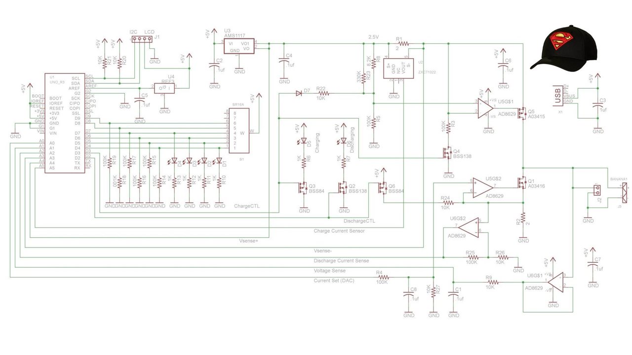
Here is the schematic of the supercapacitor meter shield:
image

Basically the circuit includes a constant current source fixed at around 100 mA and a separate variable current sink, both can be turned on and off by the UNO R4, which also can monitor voltages across both current shunts and across the supercapacitor under test. It also controls measurement cycles and the precise timing involved. Those cycles will be described in the software blog when the software has been tested. However you can deduce that for a constant current, capacitance can be calculated from the time taken to charge the capacitor. (C=i*dt/dv).

Since this is a one-off build, all voltages and currents can be calibrated by measurement with bench instrumentation. The discharge current is controlled by a DAC on the MCU. This is needed since the recommended measurement method suggests the discharge current should be 1 mA/F. All opamps are chopper-stabilized to minimize errors due to offset voltages and offset drift. The capacitor voltage measurement is buffered by a high impedance unity gain amp to minimize stray leakage from the supercapacitor under test. There are a couple of extra control FETs to ensure the current shuts off completely when the MCU wants it off.

There is an redundant current sense chip which will not be populated because it doesn't improve current measurement accuracy.

There are still a couple of tweaks in the works, such as adding more test points, but the PCB will be complete in a day or so..

Discussion

The PCB is being designed early to allow time for it to be fabricated.  This is before the software can be worked on so it needs to have enough flexibility to accommodate software revisions. I did think about how the firmware might help improve performance and accuracy, but that is a lot different than writing code. The Uno R4 has a USB port that allows interfacing to a host computer if the instrument needs to eventually talk to other instruments and computers, however that is not in the plan for this project. Some of the design choices for the system were dictated by what I had on hand, but there is also a significant amount of ordering to procure everything needed. At this time there is so much planning and design work going on, it is tough to put blogs together.

This circuit took longer than expected to design and has morphed quite a bit as I learned more about how supercapacitors work and what needs to be done to measure their parameters.

Next I need to spend time on the other 5 systems to get their PCBs designed and make sure all needed parts are at least on order. I have already ordered a bunch of stuff, but until the detailed design is done, I won't be sure I have everything on order.

Links:

 The Magic of SuperCaps 

 SuperCap Magic Meter Circuit 

 The SuperCap Rack 

 The SuperCap Magic Meter Shield 

 SuperCap Meter Shield Functional Test 

 SuperCap Magic Meter - Operational 

 SuperCap Magic Meter - Experimenting with Supercapacitors 

Experimenting with Supercapacitors Design Challenge

Cornell Dubilier Supercapacitor Technical Guide

Cornell Dubilier Supercapacitor Handling Guidelines

Challengers

Leaderboard

  • Sign in to reply
  • michaelkellett
    michaelkellett over 2 years ago

    Hello Doug,

    It would be great if you could post the schematic as a static picture or .pdf so it's easier to study it. I find videovery hard to follow for this purpose (I know others feel the opposite).

    Thanks !

    MK

    • Cancel
    • Vote Up 0 Vote Down
    • Sign in to reply
    • More
    • Cancel
  • scottiebabe
    scottiebabe over 2 years ago in reply to dougw

    Charging a 60F capacitor at 100 mA is going to result in a potential change of 1.6 mV/s. So it may take a few seconds to report a rough estimate from dQ and dV. Excited to follow along!

    • Cancel
    • Vote Up 0 Vote Down
    • Sign in to reply
    • More
    • Cancel
  • dougw
    dougw over 2 years ago in reply to scottiebabe

    The display will likely get updated 2 or 3 times per second to show progress, although a complete measurement cycle could take a long time. It may display the measurement time as well as voltage and current and maybe ESR. Capacitance, ESR and leakage would all use different types of cycle.

    • Cancel
    • Vote Up 0 Vote Down
    • Sign in to reply
    • More
    • Cancel
  • scottiebabe
    scottiebabe over 2 years ago

    Looks like a nice little widget. How often to do plan to update the display? Perhaps once per second or every 10 seconds?

    • Cancel
    • Vote Up 0 Vote Down
    • Sign in to reply
    • More
    • Cancel
  • dougw
    dougw over 2 years ago in reply to colporteur

    It is true that for a product, component tolerances often dictate accuracy.

    In this case this is a one-off build so I can measure all components and plug those values into the firmware, so tolerance isn't a major issue. Drift can be an issue, but all precise work will be done at room temperature, so thermal drift will be minimal. Long term drift isn't an issue since the project is short term. I can check if references are drifting as well, so even if there is drift I can see it.

    The components like resistors that set gain and voltage set point references will be precisely measured so accuracy of calculations will not depend on component tolerance. The reference voltage chips have a tolerance as well, but their output voltages will also be precisely measured to remove their tolerance from the accuracy equation.

    The opamps are chopper stabilized so they continuously remove any voltage offsets and offset drift.

    Things like DAC quantization errors are not important since the actual current is independently measured. However the quantization error will be minimized anyway by dividing the DAC output by 10.

    A/D resolution can be somewhat improved by oversampling and averaging. This doesn't improve accuracy, but I will do it anyway because high resolution looks deceptively like high accuracy....Relaxed

    The calculations also depend on an accurate clock - supplied by the Arduino. I might measure it but it is likely pretty good already.

    Accuracy will depend mostly on my DVM accuracy.

    I'm not actually trying to make an extremely precise lab-grade instrument, I'm just applying some ideas to make it as precise as I can - as an exercise.

    The main objective is to be able to measure supercapacitors, which my DVM fails to do. I will be happy with 5% accuracy.

    The circuit components described are to test EDLC devices. As far as testing LiCs, I'm not sure if I want to make a separate meter or just test them in a fairly narrow range that this circuit can handle. If I do it with this circuit, it can be accomplished in firmware. It is easy to cutoff discharging at any desired voltage.

    I may add some of this explanation to the blog text - thanks for the questions colporteur .

    • Cancel
    • Vote Up 0 Vote Down
    • Sign in to reply
    • More
    • Cancel
<>
element14 Community

element14 is the first online community specifically for engineers. Connect with your peers and get expert answers to your questions.

  • Members
  • Learn
  • Technologies
  • Challenges & Projects
  • Products
  • Store
  • About Us
  • Feedback & Support
  • FAQs
  • Terms of Use
  • Privacy Policy
  • Legal and Copyright Notices
  • Sitemap
  • Cookies

An Avnet Company © 2026 Premier Farnell Limited. All Rights Reserved.

Premier Farnell Ltd, registered in England and Wales (no 00876412), registered office: Farnell House, Forge Lane, Leeds LS12 2NE.

Follow element14

  • X
  • Facebook
  • linkedin
  • YouTube