Intro
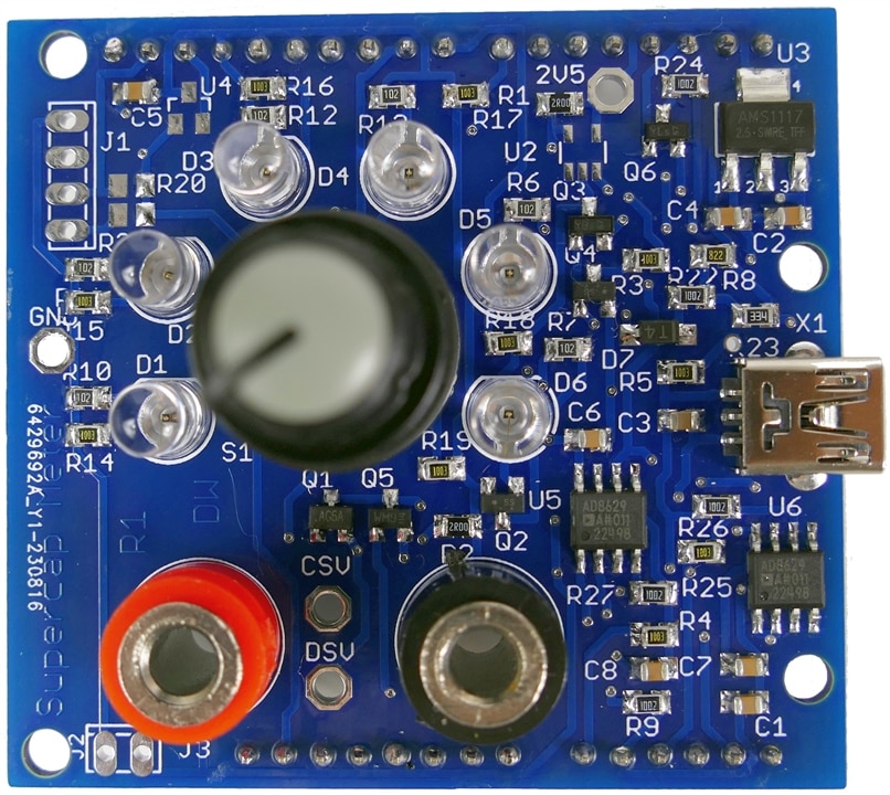
This episode of the Experimenting With Supercapacitors Design Challenge covers the build of a supercapacitor meter shield that will mate with an Arduino Uno R4 Minima. The capacitance meter design takes advantage of the 14biit A/D on the UNO R4 to provide better resolution to capacitance measurements. The PCB was fabricated with a blue solder mask to match the UNO color. The shield provides the UNO with the ability to accurately control current into and out of a capacitor under test. There is a rotary switch that can select 6 different modes of operation. The circuit operation is described in a previous blog - linked below.
The Parts Kit
Here is a quick video of the kitted parts:
I have been collecting and scrounging parts for a while. Some of the parts, such as transistors, LEDs and op-amps, are from stock I acquired before even discovering element14. The display is from an element14 prize that included some Grove modules. It is a bit of a process to go through old stock and look up all of their datasheets to see if they are suitable for the new project. There are still some parts that have been ordered but not arrived yet.
"Somebody" is going to develop an AI vision system that can recognize any part and find its datasheet. All of the technology and even most of the software to do this already exists.
The Build - Stuffing the PCB

Here is a quick video of the build:
A nice easy build, no components smaller than an 0805 or SOT23. The Arduino UNO form factor makes it a comfortable layout.
I'm using a new paperless workflow for soldering which is has pros and cons.
Paperless isn't quite as fast and the screen is not as conveniently located as where I clipped my paper docs, but there is more info available if I need it. Crossing off components as they get populated is not in the new workflow, so there is more checking involved. I will stick with it for a while and see if I can tweak the process and make it more productive.
Discussion
It was a bit of a wait for the PCB to arrive, but so far the design has gone exactly as planned, everything fits properly and initial powerup showed no surprises. The voltage reference for the MCU A/D has not arrived yet, but I can use the a rail voltage and independently measure the rail to achieve reasonable accuracy. I am waiting until I finish the meter build before diving into component testing. It isn't a suspense-building ploy, I just expect it to be a more interesting journey.
Next Steps
The project is behind schedule, so I need to pick up the pace.
Next I have to validate full functionality of the CCA and measure its components precisely. The precision of the capacitance meter will depend on measuring component values to an accuracy beyond what their nominal rated value would suggest.
Then I need to write some software to measure capacitance and characterize system performance.
Links
The SuperCap Magic Meter Shield
SuperCap Meter Shield Functional Test
SuperCap Magic Meter - Operational
SuperCap Magic Meter - Experimenting with Supercapacitors
Experimenting with Supercapacitors Design Challenge
Cornell Dubilier Supercapacitor Technical Guide


-

genebren
-
Cancel
-
Vote Up
0
Vote Down
-
-
Sign in to reply
-
More
-
Cancel
-

dougw
in reply to genebren
-
Cancel
-
Vote Up
0
Vote Down
-
-
Sign in to reply
-
More
-
Cancel
-

genebren
in reply to dougw
-
Cancel
-
Vote Up
0
Vote Down
-
-
Sign in to reply
-
More
-
Cancel
-

dougw
in reply to genebren
-
Cancel
-
Vote Up
0
Vote Down
-
-
Sign in to reply
-
More
-
Cancel
Comment-

dougw
in reply to genebren
-
Cancel
-
Vote Up
0
Vote Down
-
-
Sign in to reply
-
More
-
Cancel
Children