


Even though I ended up constructing a brand new front panel for the toy piano for this project, the rest of the enclosure of the vintage toy synth will be using the existing piano enclosure. Apart from the front panel, the other part of the piano that needs modifying for the project is the back section where I need to add a set of sockets and controls so that the synth can be easily connected to a power source, an audio output, and external MIDI gear. A second part to this task was connecting these sockets to the internal electronics of the vintage toy synth.
Construction
The sockets I have added are:
- 2x 5-pin DIN sockets (for MIDI I/O)
- 1x 6.3mm stereo jack socket (for audio output)
- 1x 2.1mm/5.5mm DC socket (for power), coupled with 1x standard SPST toggle switch (as a power switch)
The first thing I needed to do was to get out my Dremel and cut out some holes for all five components. Below is a photo of the back of the piano enclosure after I had done this:
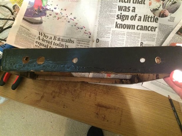
Back of the vintage toy piano with holes cut out for sockets and controls
I'm in no way saying that this is my best Dremel work - the holes aren't perfect circles or in line. However as it is a vintage hand-build piano nothing is perfectly straight anyway, so my sloppy drilling actually goes quite well with the existing enclosure!
Below are some examples of what the back will look like once the sockets and controls are added:
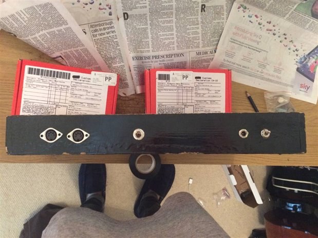
Back of the toy piano with the sockets/controls added
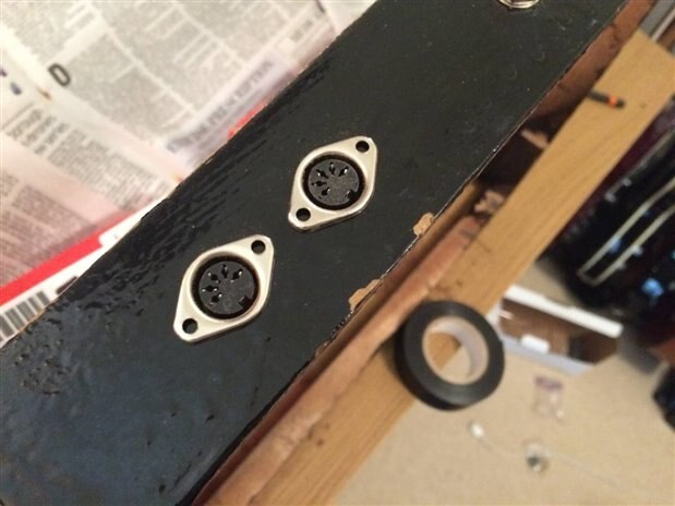
5-pin DIN MIDI sockets
6.3 mm stereo jack socket
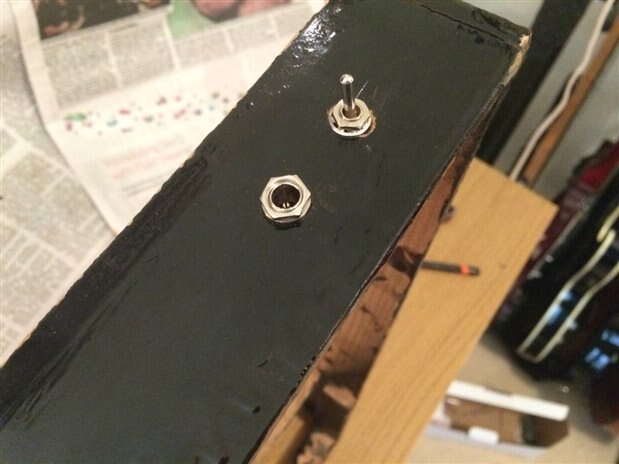
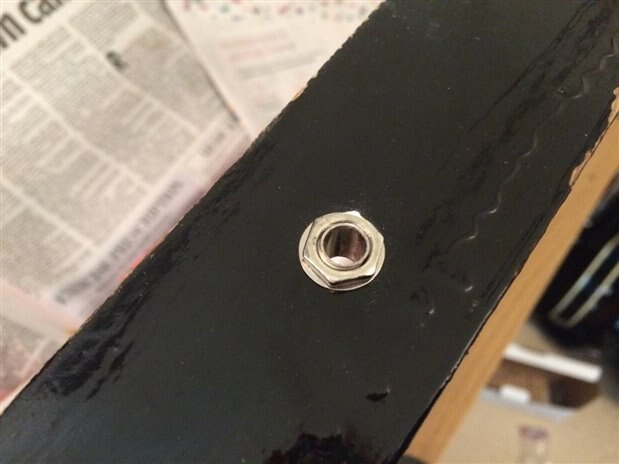
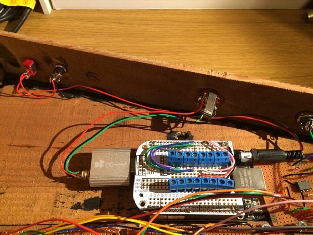
DC socket and toggle switch
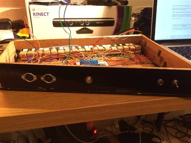
An example of the sockets with the rest of the synth
The MIDI sockets and the toggle switch were long enough to fit through the wooden panel, however the jack and DC sockets were too short to allow me to fit a washer and nut to them for securing the sockets to the panel. Therefore on the inside of the enclosure I had to cut away an area of wood around the holes for these sockets so that the components would fit correctly, as show in the below photo:
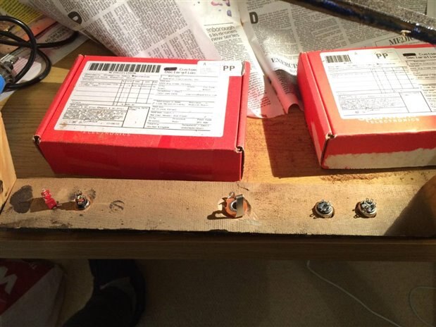
Inside of the back
Socket Choice
There were a couple of reasons why I chose these particular sockets/controls to use on the back of the synth:
- I decided to use the metal-framed MIDI sockets rather than the more-commonly used right-angle MIDI sockets as they are much easier to connect and secure to 6mm-thick wood. Also the right-angle sockets are designed to be secured to a PCB/circuit instead of the enclosure, which would have given me less freedom in regards to where I place the MIDI circuit/stripboard within the synth.
- I decided to use a 6.3mm audio jack socket instead of a 3.5mm mini jack socket as they are more commonly found on commercial synthesisers and similar products. Even though the current synth engine is just monophonic, I chose to use a stereo jack instead of a mono jack so that stereo headphones could be used without only one ear being active.
- I didn't particularly need to add a power switch, however it is a nice little extra thing to have. I am also considering having a power LED too.
Connecting to Internal Electronics
Now that I have a bunch of sockets connected to the back of my synth the user can easily apply power, get audio, and connect to MIDI gear without needing to open up the device. However these sockets need to be connected to the rest of the electronics of the synth in some way...
MIDI Sockets
Connecting these sockets were easy - If you've read my previous blogpost on the development of the MIDI I/O electronics you would have seen the circuit I made that allows MIDI gear to be connected to the BeagleBone Black via MIDI DIN sockets. Therefore here I just needed to connect these sockets to my MIDI I/O circuit via the screw terminals I added.
Audio Jack Socket
From my previous blogpost on BeagleBone Black audio you would have read that I'm using an EC Technology USB audio adapter for the audio output of the BBB within my synth, which has a standard 3.5mm stereo mini jack as the audio connector. Initially I was trying to find an existing cable/adapter that goes from a male 3.5mm jack to a female 6.3mm jack, where the socket side of the cable could be secured to a hole using a washer and nut, however I had no luck finding this cable. Therefore I ended up making my own cable, where I have attached a mini-jack plug the the jack socket using the three need wires - left (tip), right (ring), and ground (sleeve). As the cable isn't longer than 8 inches I didn't need to worry about insulating the wires to prevent noise interference.
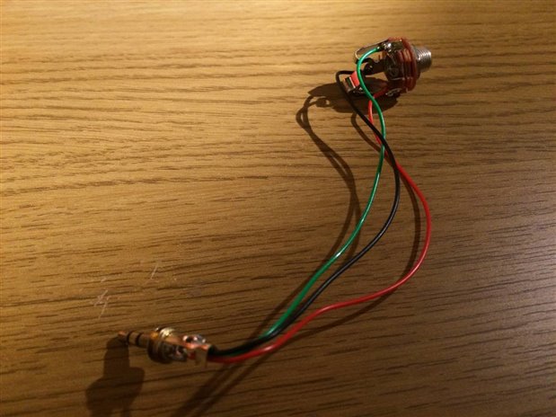
MY DIY audio cable
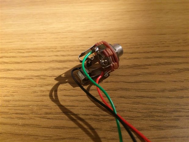
The jack socket side of the cable, which will be attached to the back of the synth
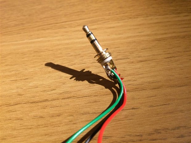
The jack plug side of the cable, that will connect to the USB audio adapter connected to the BBB
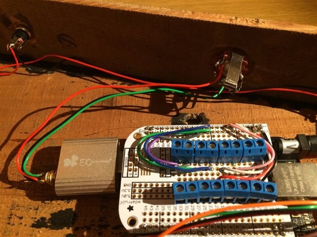
The DIY audio cable connected to the BBB
DC Power Socket
For the power socket I have essentially done the same kind of thing as that for the audio connection - I've build my own cable that goes from the socket to a DC plug that connects to the 5V power socket on the BBB. However here I have also added in the power switch that breaks the power line when turned off.
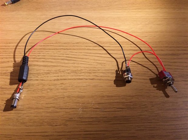
My DIY power cable
The DIY power cable connected to the BBB
Top Comments