Since my last blog I’m still traveling, therefore I could unfortunately not work much on the project. The good news is that my traveling last week was to the AgriControl conference in Seattle (Washington State University), where I got a lot of inspiration for my project.
AGRICONTROL2016: ‘The 5th IFAC Conference on Sensing, Control and Automation for Agriculture’ aims to bring together scientists, engineers, students and others working in these areas from around the world to share their latest results. The conference will provide an opportunity for learning the state-of-the-art and for discussion on past achievements, and future directions in precision and automated agriculture. The conference is also expected to provide a venue for leveraging the advances in other lateral technologies for enhancing the productivity in agriculture.
I also did a bit of research on how to do the image alignment of the two different cameras using OpenCV.
Previous posts:
[Pi IoT] Plant Health Camera #7 - Synchronizing the cameras
[Pi IoT] Plant Health Camera #6 - Putting the slave Pi to work
[Pi IoT] Plant Health Camera #5 - OpenCV
[Pi IoT] Plant Health Camera #4 - Putting the parts together
[Pi IoT] Plant Health Camera #3 - First steps
[Pi IoT] Plant Health Camera #2 - Unboxing
[Pi IoT] Plant Health Camera #1 - Application
Inspiration from the AgriControl conference
In my application I explained that the NDVI can be calculated using a red (R) and near infrared (NIR) band. Since in the PiCam NoIR the red band is given up in favor of the NIR band, we need two cameras as explained in my Pi NoIR and Catch Santa Challenge - Review . But, the NDVI also can be calculated using the blue (B) or green (G) in stead of the red (R) band, resulting in the GNDVI or BNDVI. On AgriControl Zhou et. al. [1] reported nice results, using a modified Canon camera on an optocopter for stress monitoring in bean fields using the Green NDVI (GNDVI). Quirós and Khot [2] used the GNDVI as indicator for differences in the level of irrigation for apple orchards.
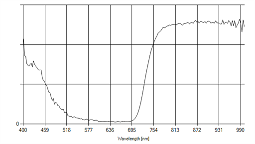
A few words should be devoted to the blue filter which comes with the PiCam NoIR. This filter is a so called ‘NGB’ or ‘infra blue’ filter.
It filters out the red part of the spectrum. I was curious about the transmission spectrum of the blue filter, so for the above mentioned readiest review I measured it with a spectrophotometer. Below is a graph of the measured spectrum.
So you can clearly see that blue (± 400 nm) green (± 500 nm) and NIR (> 700 nm) get through, while red (± 650 nm) is blocked.
So the GNDVI and BNDVI can be calculated from the three different bands of the Pi NoIR camera. Consequently no image registration is needed as the individual pixels of course perfectly match.
But I also like to have the possibility to measure the ‘real’ NDVI based on the red and NIR channel. In that case the bands come from different cameras (NIR from Picam NoIR and R from the standard Picam) and needs to be aligned. In the next section I explain how to accomplish this using OpenCV.
Image alignment using OpenCV
A search on the internet brought me at a very interesting website which explains image alignment in OpenCV [3]. The algorithm is explained on an image of a very interesting historic collection of photographs called the Prokudin-Gorskii collection. These photographs were taken by a Russian photographer in the early 1900s using one of the early color cameras. The color channels of the image are misaligned because of the mechanical nature of the camera. The author of the tutorial shows how to align the red green and blue image using a function called findTransformECC available in OpenCV 3. Without duplicating this tutorial I will briefly guide you through the steps I need specifically for my application (lesson learned from CharlesGantt). The steps needed are as follows:
- Read the images.
- Convert them to grayscale.
- Pick a motion model you want to estimate.
- Allocate space(warp_matrix) to store the motion model.
- Define a termination criteria that tells the algorithm when to stop.
- Estimate the warp matrix using findTransformECC.
- Apply the warp matrix to one of the images to align it with the other image.
Lets go briefly through the steps:
1- reading the images from the two cameras is explained in my previous blog ().
2- The images are color images, with three bands, we need to extract just the R and NIR band from the image, this can be done using:
# Convert images to gray scale
red_channel = color_image[:,:,0]
nir_channel = noir_image[:,:,0]
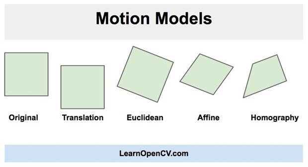
3- We need to define a motion model
(image courtesy of https://www.learnopencv.com/image-alignment-ecc-in-opencv-c-python/ )
We can do a Translation(MOTION_TRANSLATION), where the image only shifted. Only the x and y shift needs to be estimated. The Euclidean(MOTION_EUCLIDEAN) is a combination of translation and rotation, so there are three parameters; x, y and angle . The Affine(MOTION_AFFINE) is a combination of rotation, translation ( shift ), scale, and shear. This transform has six parameters. The most advanced transformation is called Homography(MOTION_HOMOGRAPHY) which adds some 3D effects to the transformation. This transform has 8 parameters.
Since the cameras are placed next to each other a translation over 1 dimension ( x ) should in principle be sufficient, but since plants are 3D object I expect that the Homography is needed for situations where there is much depth in the images. Luckily using this OpenCV function we can easily test the different options.
Code:
# Define the motion model
warp_mode = cv2.MOTION_TRANSLATION
4- A matrix for storing the model needs to be allocated:
# Define 2x3 or 3x3 matrices and initialize the matrix to identity
if warp_mode == cv2.MOTION_HOMOGRAPHY :
     warp_matrix = np.eye(3, 3, dtype=np.float32)
else :
     warp_matrix = np.eye(2, 3, dtype=np.float32)
5- Since findTransformECC is an iterative optimization function we need to define a criterium on which the iteration will stop:
# Specify the number of iterations.
number_of_iterations = 5000;

# Specify the threshold of the increment
# in the correlation coefficient between two iterations
termination_eps = 1e-10;

# Define termination criteria
criteria = (cv2.TERM_CRITERIA_EPS | cv2.TERM_CRITERIA_COUNT, number_of_iterations,  termination_eps)
6- Then we can run findTransformECC:
# Run the ECC algorithm. The results are stored in warp_matrix.
(cc, warp_matrix) = cv2.findTransformECC (red_channel,nir_channel,warp_matrix, warp_mode, criteria)
7- after the model is estimated, it can be applied on the two images and displayed
if warp_mode == cv2.MOTION_HOMOGRAPHY :
    # Use warpPerspective for Homography
    nir_aligned = cv2.warpPerspective (nir_channel, warp_matrix, (sz[1],sz[0]), flags=cv2.INTER_LINEAR + cv2.WARP_INVERSE_MAP)
else :
    # Use warpAffine for nit_channel, Euclidean and Affine
    nir_aligned = cv2.warpAffine(nir_channel, warp_matrix, (sz[1],sz[0]), flags=cv2.INTER_LINEAR + cv2.WARP_INVERSE_MAP);

# Show final results
cv2.imshow(“Aligned NIR Image", nir_aligned)
Thats it for now, in the next post I will put the software together and show my results on real images.
Just curious, which algorithm do you think will give me the best results:
Poll can be found here: Which alignment model should work for the Plant Health Camera
References
[1] Evaluation of ground, proximal and aerial remote sensing technologies for crop stress monitoring , Jianfeng Zhou *, Lav R. Khot**, Haitham Y. Bahlol**, Rick Boydston***, Phillip N. Miklas***
[2] Potential of low altitude multispectral imaging for in-field apple tree nursery inventory mapping Juan José Quirós*,**. Lav R. Khot*
[3] https://www.learnopencv.com/image-alignment-ecc-in-opencv-c-python/
stay tuned.


Top Comments
-

DAB
-
Cancel
-
Vote Up
0
Vote Down
-
-
Sign in to reply
-
More
-
Cancel
-

gpolder
in reply to DAB
-
Cancel
-
Vote Up
+1
Vote Down
-
-
Sign in to reply
-
More
-
Cancel
Comment-

gpolder
in reply to DAB
-
Cancel
-
Vote Up
+1
Vote Down
-
-
Sign in to reply
-
More
-
Cancel
Children