


With the summer kicking in India, it is too hot to be outside, Plus it's holiday season for the Institute i work with and so I got more free time. My Work-cation at Goa has me fully charged and motivated. Today I will explain though how i Implemented Tug/Snatch detection.
Recap:
The idea is simple enough: stop making people swipe a card and type a PIN at every single door. Instead, the ID card (a MAX32630FTHR + ATECC508A in your pocket) unlocks once via PIN, then silently does challenge-response crypto over Bluetooth every time you walk up to a door. If the card gets yanked off you, the IMU detects the tug and it locks itself. No PIN, no entry. For more details check the Part 1 of the series
- Identity Protocol Part 1 - Plan
- Identity Protocol - Part 2 - Django Server
- Identity Protocol - Part 3 - Unboxing and Blinking with Maxim LPSDK
- Identity Protocol - Part 4 - BLE using PAN1326B and BTstack
- Identity Protocol - Part 5 - Interfacing a Keypad
Tug detection is one of the important function to the project, as it prevents the card being stolen while in an unlocked state. Full source is in firmware/tests/imu-bmi160/ and firmware/tests/tug-detection/ in the project repo.
BMI160 Hardware
This nice little sensor from Bosch sits on the FTHR board's shared I2C bus alongside the MAX14690N PMIC. The pin mapping for I2CM2 MAP_A on the MAX32630 is:
- SDA - P5_7
- SCL - P6_0
The sensor has an address of 0x68.

Credits: mbed.com
Learning about the BMI160 Communication
Before writing a single line of LPSDK code I read through hanyazou's BMI160-Arduino library available at https://github.com/hanyazou/bmi160-arduino. It is derived from Intel's CurieIMU driver and covers the register map in. From this I surmised
1. The power-up command sequence
After power-on the BMI160 holds both accelerometer and gyroscope in suspend mode. They must be woken explicitly, in order, with startup delays that the datasheet specifies:
| Step | Register | Value | Purpose | Delay after |
| 1 | 0x7E (CMD) | 0xB6 | Soft reset | 10 ms |
| 2 | 0x7E (CMD) | 0x11 | Accel -> normal mode | 5 ms |
| 3 | 0x7E (CMD) | 0x15 | Gyro -> normal mode | 80 ms |
2. Verifying the chip with CHIP_ID
The Step that tells me things are communicating. Register 0x00 returns a fixed value of 0xD1 for the BMI160. Reading it is the simplest sanity check that I2C wiring and addressing are correct before doing anything else. The Arduino library checks this in getDeviceID().
3. Data layout: gyro first, then accelerometer
Reading 12 consecutive bytes starting at 0x0C gives you all six axes:
| Offset | Register | Content |
| 0 | 0x0C | Gyro X low byte |
| 1 | 0x0D | Gyro X high byte |
| 2 | 0x0E | Gyro Y low byte |
| 3 | 0x0F | Gyro Y high byte |
| 4 | 0x10 | Gyro Z low byte |
| 5 | 0x11 | Gyro Z high byte |
| 6 | 0x12 | Accel X low byte |
| 7 | 0x13 | Accel X high byte |
| 8 | 0x14 | Accel Y low byte |
| 9 | 0x15 | Accel Y high byte |
| 10 | 0x16 | Accel Z low byte |
| 11 | 0x17 | Accel Z high byte |
Each pair is a little-endian signed 16-bit integer:
ax = (int16_t)(buf[6] | (buf[7] << 8));
At the default range of +/-2 g, the scale is 16384 LSB per g.
4. The PMU (Power Management Unit) status register for debugging
Register 0x03 holds the current power-mode bits for each sensor: Polling this after wakeup commands confirms the device is actually ready, not just ACKing the write.
| Bits | Field | Normal value |
| [1:0] | Accel PMU | 0x01 |
| [3:2] | Gyro PMU | 0x01 (bit-pair 01 = 0x04 when shifted to [3:2]) |
Driver Development on LPSDK
MAX32630 Keeps surprising me. The LPSDK I2C API (i2cm.h) I2CM_Write cmd parameter sends a separate transaction before the data transaction. Works well for single byte reads but not for Burst reads. so a helper function needs to be written to prepend the register address into the data buffer and pass cmd=NULL in the I2CM_Write call:
/* Write one byte to a BMI160 register */
static int bmi160_write_reg(uint8_t reg, uint8_t val)
{
    uint8_t buf[2] = { reg, val };
    int ret = I2CM_Write(I2C_BUS, BMI160_ADDR, NULL, 0, buf, 2);
    return (ret == 2) ? E_NO_ERROR : E_COMM_ERR;
}
For reading, it's straight forward, but to maintain a good coding structure i will use a helper for reads which does nothng but keep the function similar to read
/* Read len bytes starting at reg */
static int bmi160_read_regs(uint8_t reg, uint8_t *data, int len)
{
int ret = I2CM_Read(I2C_BUS, BMI160_ADDR, ®, 1, data, len);
return (ret == len) ? E_NO_ERROR : E_COMM_ERR;
}
Initializing the I2C
const sys_cfg_i2cm_t cfg = {
    .clk_scale = CLKMAN_SCALE_DIV_1,
    .io_cfg    = IOMAN_I2CM2(IOMAN_MAP_A, 1),   /* P5_7=SDA, P6_0=SCL */
};
I2CM_Init(MXC_I2CM2, &cfg, I2CM_SPEED_100KHZ);
So here is the final flow
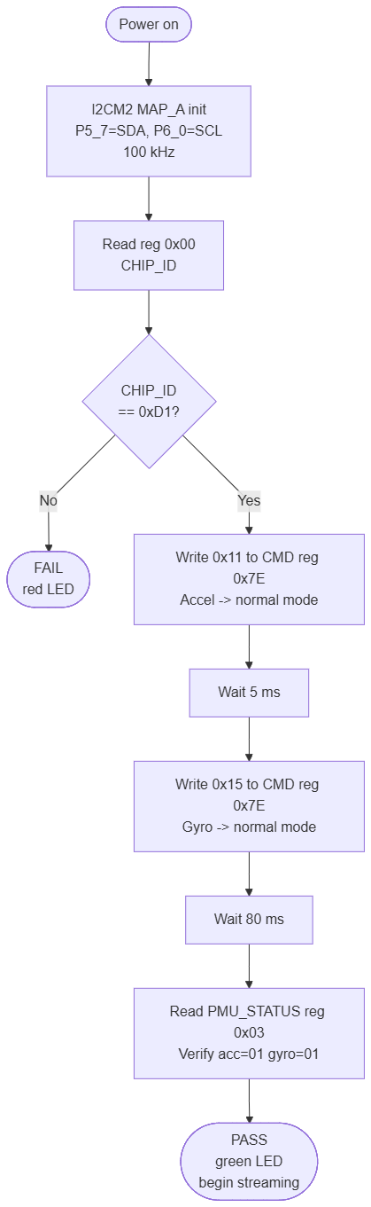
and the code equivalent to that
static int bmi160_init(void)
{
    uint8_t chip_id = 0;

    /* 1. Verify chip identity */
    if (bmi160_read_regs(BMI160_REG_CHIP_ID, &chip_id, 1) != E_NO_ERROR)
        return E_COMM_ERR;
    if (chip_id != 0xD1)
        return E_BAD_PARAM;

    /* 2. Wake accelerometer */
    bmi160_write_reg(BMI160_REG_CMD, 0x11);   /* ACC_NORMAL */
    TMR_Delay(MXC_TMR0, MSEC(5));

    /* 3. Wake gyroscope */
    bmi160_write_reg(BMI160_REG_CMD, 0x15);   /* GYR_NORMAL */
    TMR_Delay(MXC_TMR0, MSEC(80));

    return E_NO_ERROR;
}
This will help make the IMU ready to stream the data.
The Physics behind the Algorithm
3D Printing Enthusiasts who use Klipper will find this familiar - Jerk. No I am not insulting you (I hope e14's sensitive spam detection does not flag this). Jerk is the time derivative of Acceleration. It is felt when an object collides or is pulled suddenly. Just the initial bit of it. For people who ask - Why not acceleration? My answer is Acceleration happen on a daily basis during regular activity - Walking, Running etc. We want the IMU to detect when there is a sudden change in activity, when a person bumps into another (that's when the ID cards are stolen in most movies) or when it is pulled.
So to detect a jerk we calculate the acceleration change divided by the time period. The net acceleration is calculated by square root of sum of square of each component. Trying Running this at 50Hz did not work out well, it started lagging, so i resorted to next best thing approximation (I forgot the name of this approximation)
magnitude (appx) = max(|x|, |y|, |z|) + 0.5 * mid(|x|, |y|, |z|)
static int32_t accel_magnitude(int16_t ax, int16_t ay, int16_t az)
{
    int32_t x = ax < 0 ? -ax : ax;
    int32_t y = ay < 0 ? -ay : ay;
    int32_t z = az < 0 ? -az : az;
    /* Sort descending */
    if (y > x) { int32_t t = x; x = y; y = t; }
    if (z > x) { int32_t t = x; x = z; z = t; }
    if (z > y) { int32_t t = y; y = z; z = t; }
    return x + (y >> 1);   /* max + 0.5 * mid */
}
Threshold tuning
I just kept decreasing the threshold until i was satisfactory

Here is the link to full video if you are interested. - https://youtu.be/xhUsJPgzvA0 I choose 21,000 as a good balance better detecting a sharp tug and ignoring basic tugs.
Polling Loop
device_state_t state = STATE_LOCKED;
int16_t ax, ay, az;
bmi160_read_accel(&ax, &ay, &az);
int32_t prev_mag = accel_magnitude(ax, ay, az);

while (1) {
    TMR_Delay(MXC_TMR0, MSEC(20));   /* 50 Hz */

    bmi160_read_accel(&ax, &ay, &az);
    int32_t mag   = accel_magnitude(ax, ay, az);
    int32_t delta = mag - prev_mag;
    if (delta < 0) delta = -delta;
    prev_mag = mag;

    if (state == STATE_UNLOCKED && delta > JERK_THRESHOLD) {
        state = STATE_LOCKED;
        led_red();
        printf("TUG DETECTED (delta=%ld) -- LOCKED\n", (long)delta);
    }
}
I couldn't get the jerk threshold calculated on the Sensor itself and so, i just left the interrupt pin alone and decided on polling and calculating on MCU.
Code for this particular post is available at https://github.com/arvindsa/identity-protocol-e14-challenge/tree/main/firmware/tests/tug-detection
Code for entire project is available at https://github.com/arvindsa/identity-protocol-e14-challenge
Results
Results can be seen in the full video of the tug threshold test - https://youtu.be/xhUsJPgzvA0.
Final Notes
One of the important decision I have to take was to choose between an option of Calculating correct acceleration using the square root method at the cost of lower sampling rate or Having a higher sampling rate at the cost of an approximated acceleration. I went with approximation because i can appropriately change the threshold value experimentally. This will prove to be a better choice when i start integrating all the function and they take up cpu cycles. If it was actual acceleration calculation the other functionality will drag the sampling rate even lower.
The Start of the project is the Cryptographic signing by ATECC508A. Since I've worked with it before, all i have to do is port the code to match the LPSDK's function call which is almost done. I am making a small change to my project, previously in my plan it was the door device will use another ATECC508A for verification. But I realized it was not needed and so we will use software library micro-ecc for verification of the cryptographic signature. I will explain it in detail over a post. It's the write-up which is the hard part. 
